Table of Contents
Advertisement
Advertisement
Table of Contents

Related Manuals for Equinox Systems ESP-2 MI

Summary of Contents for Equinox Systems ESP-2 MI
- Page 1 ESP-2 MI Serial Hub Installation and User Guide 590-298-001E October 2004...
-
Page 3: Table Of Contents
Contents Section 1 - Introduction ........1 1.1 What You Get . - Page 4 Section 5 - Configuration Utility....... .32 5.1 Accessing the Configuration Utility ........32 Accessing with Telnet.
-
Page 5: Section 1 - Introduction
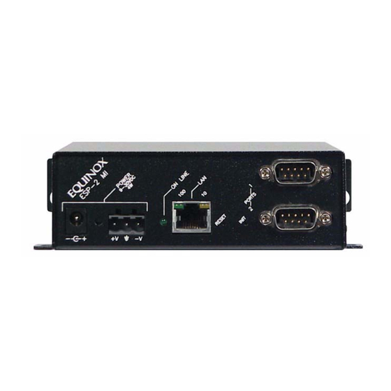
The Equinox ESP 2-port Multi-Interface (ESP-2 MI) serial hub contains an autosensing 10/100 Ethernet port and two multi-interface serial ports. The ESP-2 MI hub supports several ways to access the serial ports (see Serial Port Connection Methods and Attributes on page 10 for more information): •... -
Page 6: What You Get
530-024 (EU) 710-024 Equinox SuperSerial Software CD An Industrial Mounting Kit is available for installing the ESP-2 MI hub on a DIN rail. A modular adaptor is available for the modem emulation connection method. Contact Equinox Technical Support for details. -
Page 7: Section 2 - Hardware
INIT Reinitializing and Resetting the Hub on page 9. 2.1 Physical Interfaces Each port supports the standard RS-232 DTE serial signals via a male DB-9 connector, with the exception of RI. Equinox ESP-2 MI Serial Hub Installation and User Guide... -
Page 8: Pin Assignments
Not supported: RI, RS-422 RTS and CTS differential control signals. Unused pins (labeled N/C) should not have wires attached to them. Floating wires could cause unbalanced noise, shorten overall distances and degrade performance. Equinox ESP-2 MI Serial Hub Installation and User Guide... -
Page 9: Electrical
2.3 Electrical The ESP-2 MI has two electrical power connectors on the front of the unit. These connectors are labeled POWER 9-30 VDC 4W. You may use either one of these connectors, but not both. -
Page 10: Changing The Physical Interface Settings
Figure 2: Jumper Locations and Settings To change the physical interface settings: Place the unplugged ESP-2 MI hub on a flat surface. Use the screwdriver to loosen the two screws on either side of the unit (total of four screws). Remove the screws. -
Page 11: Installing The Hub
Replace the cover on the unit and reinstall the four screws. 2.6 Installing the Hub The ESP-2 MI serial hub may be installed on a table, on a DIN rail or on a wall. WARNING: The power outlet should be near the equipment and be easily accessible. - Page 12 DHCP server. • After the ESP-2 hub acquires an IP address (by any method), it will no longer use BootP or DHCP. Therefore, you cannot change the network values using this method. Equinox ESP-2 MI Serial Hub Installation and User Guide...
-
Page 13: Reinitializing And Resetting The Hub
You may also reset (reboot) the hub using the web interface (see Rebooting the Hub on page 30) or the configuration utility (see Rebooting the Hub on page 38). Equinox ESP-2 MI Serial Hub Installation and User Guide... -
Page 14: Section 3 - Serial Port Connection Methods And Attributes
ESP-2 serial hub. The driver creates a virtual COMM or tty port interface within the host’s operating system. Table 6 describes this method’s configurable items for each serial port. Equinox ESP-2 MI Serial Hub Installation and User Guide... -
Page 15: Telnet Server
Valid values are 1024-65535. The default value is 3001 for port 1 and 3002 for port 2. Equinox ESP-2 MI Serial Hub Installation and User Guide... -
Page 16: Raw Tcp Server
Valid values are 1024-65535. The default value is 4001 for port 1 and 4002 for port 2. Equinox ESP-2 MI Serial Hub Installation and User Guide... -
Page 17: Raw Tcp Client
Enables or disables the raw TCP client connection method on the port. The Enable/ default value is disabled. This method cannot be enabled if any other serial disable port connection method is already enabled on the port. Equinox ESP-2 MI Serial Hub Installation and User Guide... -
Page 18: Modem Emulation
The hub presents a Hayes-compatible modem interface to the attached serial device by accepting AT modem commands and performing the required functions. This connection method is valid only on RS-232 ports. Equinox ESP-2 MI Serial Hub Installation and User Guide... - Page 19 The configured Echo value will be used for subsequent connections. Equinox ESP-2 MI Serial Hub Installation and User Guide...
-
Page 20: Modem Commands
Table 11 lists the supported AT modem commands. All other AT commands will be ignored or cause an error, depending on the configured response code and verbose response settings. With the exception of the ? and ATDT commands, multiple Equinox ESP-2 MI Serial Hub Installation and User Guide... - Page 21 Subsequent connections will use the configured Response Codes option value. Sets the value in register S0, which specifies the number of rings before auto ATS0=n answer. The default value is 1. Equinox ESP-2 MI Serial Hub Installation and User Guide...
-
Page 22: Command Mode
There must be a one-second guard time (no data traffic) before sending the +++. • There must not be a delay longer than one second between each +. • There must be another one-second guard time after the last +. Equinox ESP-2 MI Serial Hub Installation and User Guide... -
Page 23: Response Codes
DCD by the serial device, which is usually a PC when modem emulation is used). If the TCP connection drops, DTR will be lowered to indicate a Carrier Drop to the attached serial device. Equinox ESP-2 MI Serial Hub Installation and User Guide... -
Page 24: Incoming Calls
NOTE: When a port is configured for the serial port redirection connection method, the attributes are specified within the protocol. Therefore, although you may change the attributes, any changes you specify will not take effect. Equinox ESP-2 MI Serial Hub Installation and User Guide... - Page 25 Stop bits Default value: 1 Valid values: None, XON/XOFF and RTS/CTS Default value: None Flow control Flow control settings are full duplex. RTS/CTS flow control is valid only on RS-232 ports. Equinox ESP-2 MI Serial Hub Installation and User Guide...
-
Page 26: Section 4 - Web Interface
FLASH image or downloading a configuration file. -or- The next connection is established with the port after the change was made - this applies to changing serial port attributes or connection methods. Equinox ESP-2 MI Serial Hub Installation and User Guide... -
Page 27: Passwords
0.0.0.0. If you changed any values, click the Apply button. The EEPROM configuration is modified, but the change does not take effect until the next reboot of the ESP-2 Equinox ESP-2 MI Serial Hub Installation and User Guide... -
Page 28: Displaying Or Changing Port Interface, Attributes And Connection Methods
Enable the Serial Connection Methods radio button. Click the Apply button. On the display, radio buttons indicate if a connection method is enabled or disabled. Text boxes contain current values for applicable features. Equinox ESP-2 MI Serial Hub Installation and User Guide... -
Page 29: Displaying Hardware Information
FLASH memory. Before updating a FLASH image, you must configure a TFTP server on the target server system and install the new FLASH image in the appropriate location, which is usually relative to the TFTP root directory. Equinox ESP-2 MI Serial Hub Installation and User Guide... -
Page 30: Displaying Or Changing Configurable Features
When enabled, the SNMP interface is used for monitoring and limited Allow administrative configuration of the ESP-2 serial hub. When disabled, tools such as functions via SNMP EquiView Plus and espdiag will not work. The default value is enabled. Equinox ESP-2 MI Serial Hub Installation and User Guide... -
Page 31: Downloading A Configuration File
Reboot button. 4.10 Displaying General Statistics The General Statistics display includes the items described in Table 17. All values are cumulative since the ESP-2 serial hub was last reset. Equinox ESP-2 MI Serial Hub Installation and User Guide... -
Page 32: Displaying Port Statistics
M=mark or S=space) and number of stop bits (1 or 2). Frame/Parity/Overrun Number of framing errors, parity errors and overruns. To display port statistics: Select Port Statistics from the Main Menu. Equinox ESP-2 MI Serial Hub Installation and User Guide... -
Page 33: Displaying Connection Status
Server is establishing a connection. Active Server and ESP-2 hub are connected. UDP State Timeout Connection is being dropped due to lost communication with the server. Terminated Connection has been dropped. Equinox ESP-2 MI Serial Hub Installation and User Guide... -
Page 34: Rebooting The Hub
After the reinitialization completes, the web interface will try to reconnect to the hub, using the predefined IP address (192.1.1.1). If this fails, or if the web interface does not return within 30 seconds, direct your browser to the predefined IP address (192.1.1.1). Equinox ESP-2 MI Serial Hub Installation and User Guide... - Page 35 You may also reinitialize the ESP-2 serial hub using the configuration utility (see Reinitializing the Hub on page 38) or the INIT button on the front panel (see Reinitializing on page 9). Equinox ESP-2 MI Serial Hub Installation and User Guide...
- Page 36 Accessing on port 1 or 2 using the configuration utility connection method After the ESP-2 serial hub has a configured IP address, the administrator may enable the serial configuration utility on port 1 or 2. When this connection method is Equinox ESP-2 MI Serial Hub Installation and User Guide...
- Page 37 (usually ). If the serial configuration utility connection method is used to access the utility and an inactivity time-out is enabled, a session will end if the inactivity period is reached. Equinox ESP-2 MI Serial Hub Installation and User Guide...
-
Page 38: Displaying Or Changing Network Configuration Values
(see Rebooting the Hub on page 38), the web interface (see Rebooting the Hub on page 30) or the RESET button on the front panel (see Resetting on page 9). Equinox ESP-2 MI Serial Hub Installation and User Guide... -
Page 39: Displaying Or Changing Port Interface, Attributes And Connection Methods
If you reply no, nothing more is done for that connection method. If you reply yes (that is, to enable that method), the configurable parameters are displayed and you are prompted for values. Equinox ESP-2 MI Serial Hub Installation and User Guide... -
Page 40: Displaying Or Updating Flash Memory
FLASH memory. Before updating a FLASH image, you must configure a TFTP server on the target server system and install the new FLASH image in the appropriate location, which is usually relative to the tftp root directory. Equinox ESP-2 MI Serial Hub Installation and User Guide... -
Page 41: Displaying Or Changing Configurable Features
From the Server Configuration menu, enter to select Configuration File Download. You are prompted to specify the TFTP server IP address and the pathname of the configuration file. Enter those values. Equinox ESP-2 MI Serial Hub Installation and User Guide... -
Page 42: Displaying Port Statistics
5.13 Displaying Port Statistics The Port Statistics display includes the information described in Table 18 on page 28 for each port. All values are cumulative since the ESP-2 serial hub was last reset. Equinox ESP-2 MI Serial Hub Installation and User Guide... -
Page 43: Displaying And Using Debug Features
The datascope shows all data sent and received on the specified serial port. Each line displays 16 bytes in hex and ASCII. To escape to a shell, enter from the Debug Menu. Equinox ESP-2 MI Serial Hub Installation and User Guide... -
Page 44: Section 6 - Configuration Files
• Parameters with values that enable or disable connection methods or features use a space between the keyword and the value. For example: port 2 tcpserver enable monitordcd enable ipviadhcp disable Equinox ESP-2 MI Serial Hub Installation and User Guide... -
Page 45: Port Connection Method Commands
Port Telnet Server command The Port Telnet Server command enables or disables the Telnet server connection method on a serial port. See Table 7 on page 11 for parameter descriptions and rules for use. Equinox ESP-2 MI Serial Hub Installation and User Guide... -
Page 46: Port Tcp Server Command
The Port Configuration Utility command enables or disables the configuration utility connection method on a serial port. See Table 13 on page 20 for parameter descriptions and rules for use. PORT <port>|ALL CONFIGUTIL ENABLE|DISABLE [TIMEOUT=<sec>] Equinox ESP-2 MI Serial Hub Installation and User Guide... -
Page 47: Port Attributes Command
When using the web interface, follow the instructions in Downloading a Configuration File on page 27. When using the configuration utility, follow the instructions in Downloading a Configuration File on page 37. Equinox ESP-2 MI Serial Hub Installation and User Guide... -
Page 48: Completion Status
Configuration File Download from the Main Menu. Any errors will be posted in the Status from last operation field. If the last operation completed successfully, the field will be blank. Equinox ESP-2 MI Serial Hub Installation and User Guide... -
Page 49: Declaration Of Conformity
Canada This digital apparatus does not exceed the Class A limits for radio noise emissions from digital apparatus set out in the Radio Interference Regulations of the Canadian Department of Communications. Equinox ESP-2 MI Serial Hub Installation and User Guide... -
Page 50: European Union
Communications du Canada. European Union WARNING: This is a Class A product. In domestic environment, this product may cause radio interference in which case the user may be required to take adequate measures. Equinox ESP-2 MI Serial Hub Installation and User Guide... - Page 51 3 setting RS-485 transfer mode 35 displaying information in the configura- updating FLASH 36 tion utility 36 using debug features 39 displaying information in the web Configuration utility connection method Equinox ESP-2 MI Serial Hub Installation and User Guide...
- Page 52 41 setting in the configuration utility 34 setting in the configuration utility 35 setting in the web interface 23 setting in the web interface 24 Pin assignments Specifications 5 Equinox ESP-2 MI Serial Hub Installation and User Guide...
- Page 53 27 displaying hardware information 25 displaying port statistics 28 downloading a configuration file 27 rebooting 30 reinitializing 30 setting configurable features 26 setting connection methods 24 setting network address values 23 Equinox ESP-2 MI Serial Hub Installation and User Guide...
- Page 54 Equinox ESP-2 MI Serial Hub Installation and User Guide...
-
Page 55: Limited Warranty
LIMITED WARRANTY Equinox warrants that the Product(s) shall be free from manufacturing defects in materials and workmanship for a period of five (5) years from the date of delivery provided that the Product was properly installed and used. Defects, malfunctions or failures of the warranted Product caused by damage resulting from acts of God (such as floods, fire, etc.), environmental and atmospheric disturbances, other external forces such as power line disturbances, host computer malfunction, plugging the... - Page 56 Equinox Systems One Equinox Way Sunrise, Florida 33351-6709 (954) 746-9000 Fax: (954) 746-9101 ftp.equinox.com www.equinox.com support@equinox.com...
Need help?
Do you have a question about the ESP-2 MI and is the answer not in the manual?
Questions and answers