Table of Contents
Advertisement
Quick Links
WARRANTY
Flyzone guarantees this kit to be free from defects in both
material and workmanship at the date of purchase. This warranty
does not cover any component parts damaged by use or
modification. In no case shall Flyzone's liability exceed the
original cost of the purchased kit. Further, Flyzone reserves
the right to change or modify this warranty without notice.
In that Flyzone has no control over the final assembly or material
used for final assembly, no liability shall be assumed nor
accepted for any damage resulting from the use by the user of
the final user-assembled product. By the act of using the
user-assembled product, the user accepts all resulting liability.
If the buyer is not prepared to accept the liability associated
with the use of this product, the buyer is advised to return
READ THROUGH THIS MANUAL BEFORE STARTING CONSTRUCTION. IT CONTAINS IMPORTANT
INSTRUCTIONS AND WARNINGS CONCERNING THE ASSEMBLY AND USE OF THIS MODEL.
© 2012 Hobbico
®
, Inc. All rights reserved.
SPECIFICATIONS
59.5 in
Wingspan:
[1510mm]
™
Wing
430 in
Area:
[27.7 dm
3– 3.25 lb
Weight:
[1360–1470 g]
Wing
16–17 oz/ft
Loading:
[49– 52 g/dm
this kit immediately in new and unused condition to the
place of purchase.
To make a warranty claim send the defective part or item to
Hobby Services at the address below:
Include a letter stating your name, return shipping address, as
much contact information as possible (daytime telephone
number, fax number, e-mail address), a detailed description of
the problem and a photocopy of the purchase receipt. Upon
receipt of the package the problem will be evaluated as quickly
as possible.
INSTRUCTION
MANUAL
38.5 in
Length:
[980mm]
2
5-channel
Radio:
2
]
radio system
40mm dia.
Motor:
850kV outrunner,
2
40A ESC,
2
12x6 propeller
]
Hobby Services
3002 N. Apollo Dr. Suite 1
Champaign IL 61822 USA
FLZA4020 FLZA4022 Mnl
Advertisement
Table of Contents

Subscribe to Our Youtube Channel
Related Manuals for Flyzone DHC-2 Beaver


Summary of Contents for Flyzone DHC-2 Beaver
-
Page 1: Instruction Manual
To make a warranty claim send the defective part or item to modification. In no case shall Flyzone’s liability exceed the Hobby Services at the address below: original cost of the purchased kit. Further, Flyzone reserves the right to change or modify this warranty without notice. -
Page 2: Table Of Contents
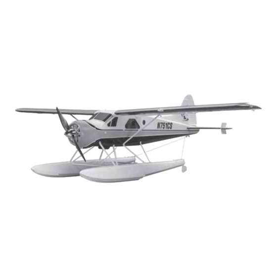
Thank you for purchasing the Flyzone 1/10 -scale de Havilland PROTECT YOUR MODEL, YOURSELF AND OTHERS... DHC-2 Beaver RTF/Tx-R. For anybody who enjoys fl ying fl oat FOLLOW THESE IMPORTANT SAFETY PRECAUTIONS planes or who aspires to do so for the fi rst time, the Flyzone 1. -
Page 3: Required For Completion
® replaced with a Deans Ultra Plug male connector which will We, as the kit manufacturer, provide you with a top quality, require soldering (but is a simple task for those so equipped). thoroughly tested kit and instructions, but ultimately the quality and fl... -
Page 4: Contents
Parts may also be ordered directly from Hobby Services by Be certain to specify the order number exactly as listed in the calling (217) 398-0007, or via facsimile at (217) 398-7721, but Replacement Parts List. Payment by credit card or personal full retail prices and shipping and handling charges will apply. -
Page 5: Assembly
ASSEMBLY Mount the Floats NOTE: This instruction manual applies to both the RTF and Tx-R editions of the de Havilland Beaver. If assembling the RTF edition, simply skip steps that do not apply. Mount the Landing Gear ❏ 1. Use a #2 Phillips screwdriver to fasten both main landing gears to the fuselage with three M3x16 screws in each side. -
Page 6: Mount The Horizontal And Vertical Stabilizer
❏ 4. Connect a small rubber band to each fl oat and water rudder as shown. ❏ 2. Use eight M2.5x8 screws to fasten the braces to the ❏ 5. Fasten the wire hooks on the end of each rudder line fl... - Page 7 ❏ 2. Connect the elevator pushrod to the bottom hole in the elevator horn as shown. ❏ 4. Key the rudder torque rod down into the receptacle while fi tting the vertical stabilizer (fi n) into the fuselage. Tightly press the assembly down into position.
-
Page 8: Install The Battery
❏ 2. Cut a 3" [76mm] strip from the softer, “loop” side and attach it to the battery so the larger “discharge” wires will be on the right side as shown. (This will position the wires opposite the receiver for a better fi t.) Hook Up the Rudder and Elevator Down ❏... -
Page 9: Mount The Wings
single, lower tone beep (“BEEEP”) followed by a shorter, higher tone beep (“beep”). If the chimes and beeps do not sound in this manner refer to “MOTOR/ESC OPERATION” on page 15 to setup the transmitter and ESC correctly. ❏ 5. Reinstall the screw, but do not tighten yet. With the transmitter and receiver on, center the elevator and tighten the screw to lock the pushrod down. - Page 10 ❏ 3. Mount the left wing the same way. ❏ 4. Mount the top of each wing strut to the wing with a M2.5x8 machine-thread screw. ❏ 2. Guide the wires from the right wing into the fuselage, then slide the wing joiner tube and the fl ap pushrod wire through the corresponding holes.
-
Page 11: Hook Up The Flaps And Ailerons
Hook Up the Flaps and Ailerons ❏ 2. Turn on the transmitter and install and connect the battery. Then install and secure the hatch. ❏ 1. Connect the wing lighting wires and the aileron servo wires to the lighting and fl ap wiring harnesses coming from the receiver. -
Page 12: Final Flight Preparation
FINAL FLIGHT PREPARATION Check the Control Throws Because the servos and pushrods are factory-installed the control throws should already be correct, but because of the effect the control throws can have on a model, it’s always a good idea to check them anyway. 4-Channel Radio Set Up (Standard Mode 2) RUDDER... -
Page 13: Check The C.g
More Control Throw Less Control Throw Pushrod Pushrod Farther Out Farther In ❏ 4. If any of the control throws require adjustment use the programming in your transmitter to increase or decrease the throws accordingly. If the programming isn’t enough or if your radio doesn’t have adjustable throws, the pushrod connectors Recommended Control Surface Throws on the servo arms can be relocated in different holes inward... -
Page 14: Motor Safety Precautions
❏ ❏ 1. Mark the forward and aft C.G. limits on both sides of 3. Install the battery, battery hatch and cabin hatch. At the bottom of the wing 2" and 2-1/2" [51mm and 64 mm] back this point the Beaver must be in ready-to-fl y condition with from the leading edge where shown—using narrow strips of everything attached and installed including the fl... -
Page 15: Motor / Esc Operation
● Keep all loose clothing, long hair or any other loose objects Unless weather conditions are terrible, you should have no such as pencils or screwdrivers that may fall out pockets trouble fl ying the Beaver from either rough or calm water. away from the propeller. -
Page 16: Repairs
The Beaver is made from injection-molded EPO (expanded polyolefi n) foam which can be glued with just about anything. Most people use regular CA. With CA no clamping is required, but some prefer softer, more fl exible adhesives such as white glue or canopy glue.
Need help?
Do you have a question about the DHC-2 Beaver and is the answer not in the manual?
Questions and answers