Table of Contents
Advertisement
Quick Links
Advertisement
Table of Contents

Related Manuals for GAI-Tronics Titan Illuminated Crossing Telephone


Summary of Contents for GAI-Tronics Titan Illuminated Crossing Telephone
- Page 1 Installation and User Guide Titan Illuminated Crossing Telephone...
-
Page 3: Table Of Contents
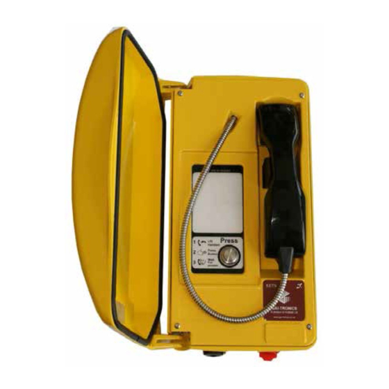
Ringer Equivalence Number (REN) ..........3 Suitability For Use ................4 Preparation ..................4 INSTALLATION ..................5 Vertical Surface or Wall Mounting ............ 5 Pole Mounting................... 8 Post Mounting................... 9 Connections and Cabling ............... 10 Approvals .................... 11 Titan Illuminated Crossing Telephone... - Page 4 COMPONENTS OF THIS TELEPHONE WHILST UNPACKING, PREPARING AND INSTALLING IT IN INCLEMENT WEATHER CONDITIONS OR BY NEGLIGENCE. FAILURE TO CARRY OUT THIS BASIC FUNCTION WILL INVALIDATE YOUR WARRANTY Figure 1 – Titan Illuminated Crossing Telephone at a glance Titan Illuminated Crossing Telephone...
-
Page 5: Pre-Installation
Note: Some PBX/PABX lines have different capabilities to the public network and the Installation Handbook should be consulted for information. When the Crossing Telephone is 3-wire connected with different models of telephone, then full performance cannot be guaranteed. Titan Illuminated Crossing Telephone... -
Page 6: Suitability For Use
2.3.2 Timer Selection Set the call time-out selector as required. If set to the ENABLE position, calls will terminate after approximately 7 minutes even if the handset is still off hook. Titan Illuminated Crossing Telephone... -
Page 7: Installation
2. Open the cover, release the front plate from the rear enclosure by unscrewing the four captive screws using a 3mm socket wrench provided. Figure 3 – Releasing the front plate 1. Remove the RED blanking plug from the cable entry hole leaving the YELLOW plug in situ. Titan Illuminated Crossing Telephone... - Page 8 WARNING:.Your warranty will be invalidated if :- 1. Any fixing hole made in the rear enclosure is left unused. 2. Any additional holes are drilled into the telephone enclosure. Titan Illuminated Crossing Telephone...
- Page 9 Figure 8 – Plastic bush knockout 6. Insert the cable through the gland body and screw down the gland nut sufficient to clamp the cable and make a seal. Titan Illuminated Crossing Telephone...
-
Page 10: Pole Mounting
IMPORTANT advice in Vertical Surface or Wall Mounting regarding extra holes and warranty invalidation. 3. Attach the pole mounting clamp assemblies to the rear enclosure using the M6 x 25 screws provided - see Figure 14 – Pole mounting. Titan Illuminated Crossing Telephone... -
Page 11: Post Mounting
Vertical Surface or Wall Mounting. 4. Offer the rear enclosure into position on the bracket with cable passing through the entry gland. 5. Pass about 150mm of cable through the gland and tighten it firmly on to the cable. Titan Illuminated Crossing Telephone... -
Page 12: Connections And Cabling
3 to terminal 10. To enable ringing link terminals 5 & 6. Linking terminals 7 & 8 will power the illuminated panel and switch. Illumination current will be interrupted if the handset integrity loop is broken. Titan Illuminated Crossing Telephone... -
Page 13: Approvals
Declaration of Conformity In accordance with European Directive 1999/5/EC (R&TTE) GAI-Tronics Ltd., of Brunel Drive, Stretton business Park, Burton upon Trent, Staffordshire, England, DE13 0BZ, declare under their sole responsibility that the following product is in conformity with the standards listed below and hold the relevant technical documentation at the above address. - Page 14 Company reserves the right to change specifications without notice. The contents of this publication are confidential, are the property of GAI-Tronics, and may not be reproduced, wholly or in part, without their written permission. E&OE. Document ref: 502-20-0096-001 issue 1. Nov 2003 CN21283...
Need help?
Do you have a question about the Titan Illuminated Crossing Telephone and is the answer not in the manual?
Questions and answers