Table of Contents
Advertisement
KX400-8XV V2.0 Series
Copyright
All rights are reserved. No part of this publication may be reproduced, transmitted, transcribed,
stored in a retrieval system or translated into any language or computer language, in any form or by
any means, electronic, mechanical, magnetic, optical, chemical, manual or otherwise, without the
prior written permission of the company. Brands and product names are trademarks or registered
trademarks of their respective companies.
The vendor makes no representations or warranties with respect to the contents herein and especially
disclaim any implied warranties of merchantability or fitness for any purpose. Further the vendor
reserves the right to revise this publication and to make changes to the contents herein without
obligation to notify any party beforehand. Duplication of this publication, in part or in whole, is not
allowed without first obtaining the vendor's approval in writing.
Disclaimer
We make no warranty of any kind with regard to the content of this user's manual. The content is
subject to change without notice and we will not be responsible for any mistakes found in this user's
manual. All the brand and product names are trademarks of their respective companies.
FCC Compliance Statement
This equipment has been tested and found to comply with the limits of a Class B digital device,
pursuant to Part 15 of the FCC Rules. These limits are designed to provide reasonable protection
against harmful interference in a residential installation. This equipment generates, uses and can
radiate radio frequency energy and, if not installed and used in accordance with the instructions, may
cause harmful interference to radio communications. Operation of this equipment in a residential
area is likely to cause harmful interference in which case the user will be required to correct the
interference at his own expense. However, there is no guarantee that interference will not occur in a
particular installation.
120410063M2N
Advertisement
Table of Contents

Subscribe to Our Youtube Channel
Related Manuals for Albatron KX400-8XV


Summary of Contents for Albatron KX400-8XV
- Page 1 KX400-8XV V2.0 Series Copyright All rights are reserved. No part of this publication may be reproduced, transmitted, transcribed, stored in a retrieval system or translated into any language or computer language, in any form or by any means, electronic, mechanical, magnetic, optical, chemical, manual or otherwise, without the prior written permission of the company.
- Page 2 Addendum of KX400-8XV Series V3.0 In the KX400-8XV Series V3.0, we upgraded the AC’97 Audio Codec from ALC650 to ALC655 and the LAN Controller from 3C910 to 3C920. If you want to update the BIOS to V3.0, please refer to version R3.XX. For AC’97 controller driver updates please refer to the version 3.49 or later.
-
Page 3: Package Contents
Do not touch the IC chips, leads, connectors or other components. Unplug the AC power when you install or remove any device on the mainboard. Package Contents KX400-8XV V2.0/ KX400-8XV Pro V2.0 mainboard IDE Cable FDC Cable USB Bracket (optional) Installation and Setup Driver CD KX400-8XV V2.0 Series User Manual... -
Page 4: User Manual
KX400-8XV V2.0 Series ® VT8377A (KT400A) & VT8235 ® Supports Socket 462 AMD Athlon XP / Athlon / Duron / Barton Processors USER Manual Operating System: ® Supports most popular operating systems: Windows 9X/ME/2000/XP etc. Dimensions (ATX form-factor): 200mm x 293mm (WxL) -
Page 5: Table Of Contents
Contents CHAPTER 1. GETTING STARTED ..................1 ........................1 NTRODUCTION ........................2 PECIFICATION ......................5 UICK ONTENT ABLE ........................6 ONFIGURATION ....................8 ARDWARE NSTALLATION CHAPTER 2. BIOS SETUP ....................22 ........................22 NTRODUCTION ......................... 24 BIOS F ....................26 DVANCED EATURES .................... -
Page 6: Chapter 1. Getting Started
The series also comes with six USB 2.0 ports. The KX400-8XV Pro also comes with a LAN Chip (3Com) which supports a back panel LAN port. The company’s 3 Year Limited Warranty for this product covers both labor costs and replacement parts during the 1st year. -
Page 7: Specification
KX400-8XV V2.0 Series Specification CPU: Supports Socket 462 (Socket A) ® Supports AMD Athlon XP , Athlon , Duron , Barton processors Speed: 200/ 266/ 333 MHz Front Side Bus frequency 33 MHz, 32 bit PCI interface (PCI 2.2 compliant) 66 MHz AGP 2.0 compliant interface that supports 2X/ 4X data transfer modes... -
Page 8: Flash Memory
SNR>95 db through mixer and DAC AC-3 playback required for DVD title applications 6-channel playback capability (Super 5.1 Channel Audio Effect) LAN Chip: (only for KX400-8XV Pro) Provides Auto-negotiation (NWAY) function of full/half duplex operation for both 10 Mbps and 100 Mbps... -
Page 9: Universal Serial Bus
KX400-8XV V2.0 Series I/O facilities: One multi-mode Parallel Port capable of supporting the following specifications: 1. Standard & Bi-direction Parallel Port 2. Enhanced Parallel Port (EPP) 3. Extended Capabilities Port (ECP) Supports two serial ports, 16550 UART Supports PS/2 mouse and PS/2 keyboard Supports 360 KB, 720 KB, 1.2 MB, 1.44 MB, and 2.88 MB floppy disk drives... -
Page 10: Quick Content Table
KX400-8XV V2.0 Series Quick Content Table Function Content Location Page CPU Socket 462 DIMM 1、2、3 DDR DIMM Sockets ATX Power Connector ATX_ PWR IDE Connectors IDE1/IDE2 FDC Connector AGP Slot PCI 1、2、3、4、5 PCI Slots CPU FAN、Chassis FAN、 CPUFAN、CHASFAN、AUXFAN Auxiliary FAN SW/LED、PWRLED... -
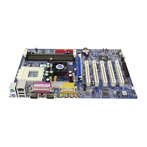
Page 11: Configuration
KX400-8XV V2.0 Series Configuration Layout of KX400-8XV Pro KB/MS CPUFAN Socket 462 USB/LAN PRT/COM ATX_PWR KT400A AUXFAN IDE1 IDE2 SOUND CD-IN PCI1 PCI2 BAT1 SPDIF PCI3 Chip VT8235 PCI4 FRONT AUDIO PCI5 Phoenix BIOS PWRLED Winbond SPEAKER W83697HF CHASFAN USB2... - Page 12 KX400-8XV V2.0 Series Layout of KX400-8XV KB/MS CPUFAN Socket 462 PRT/COM ATX_PWR KT400A AUXFAN IDE1 IDE2 SOUND CD-IN PCI1 PCI2 BAT1 SPDIF PCI3 VT8235 PCI4 FRONT AUDIO PCI5 Phoenix BIOS PWRLED Winbond SPEAKER W83697HF CHASFAN USB2 USB3 SW/LED...
-
Page 13: Hardware Installation
KX400-8XV V2.0 Series Hardware Installation This section will assist you in quickly installing your system hardware. Wear a wrist ground strap before handling components. Electrostatic discharge may damage your system components. CPU Processor Installation ® This mainboard supports AMD Athlon XP... -
Page 14: Fan Headers
KX400-8XV V2.0 Series FAN Headers Three power headers are available for cooling fans, which play an important role in maintaining the ambient temperature in your system. +12V Sense Ground S oc ke t 4 62 CPUFAN +12V VT8377A Ground AUXFAN... -
Page 15: Watch Dog Timer
KX400-8XV V2.0 Series Formulas CPU Speed = CPU Clock Ratio * CPU Host Frequency DDR Speed = DDR: CPU Ratio * CPU Host Frequency (The CPU Clock Ratio is usually locked by the CPU manufacturer which means it will not be displayed. -
Page 16: Memory Installation
KX400-8XV V2.0 Series Memory Installation The series contain 3 sockets, which use 184- pin DDR SDRAM with a total memory capacity of up to 3 GB. You can install unbuffered/ registered non-ECC DDR400/ 333/ 266 (PC3200/ 2700/ 2100)SDRAM. DIMM1 DIMM2... -
Page 17: Back Panel Configuration
The series also provides two USB headers on the board allowing for 4 more USB ports. These attach to USB connectors embedded into the computer case or connected to a USB connector bracket (optional). The KX400-8XV Pro also provides a LAN port. You can plug LAN devices directly into this connector. -
Page 18: Serial And Parallel Interface Ports
KX400-8XV V2.0 Series Serial and Parallel Interface Ports The series come equipped with two serial ports and one parallel port. Print Port COM1 COM2 The Serial Interface: COM1/ COM2 The serial interface port is sometimes referred to as a RS-232 port or an asynchronous communication port. -
Page 19: Connector Configuration
KX400-8XV V2.0 Series Connector Configuration Front Panel Indicator: SW/LED、PWRLED PWRLED SW/LED Pin Assignment Function Pin Assignment Function HD LED (+) Hard Drive ACPI LED (+) POWER HD LED (-) ACPI LED (-) RST SW (-) Reset PWR SW (+) Power-on... - Page 20 KX400-8XV V2.0 Series SPEAKER (Speaker Connector) An front panel speaker can be connected to this connector. When you boot your computer, the speaker sounds “normal beep”. If there is something wrong during the Power On Self-Test, the speaker sounds “irregular beep” to warning you.
- Page 21 KX400-8XV V2.0 Series Headers & Jumpers Front USB Headers: USB2 / USB3 5VSB 5VSB DATA_A- DATA_B- DATA_A+ DATA_B+ Ground Ground USB2 5VSB 5VSB DATA_A- DATA_B- DATA_A+ DATA_B+ Ground Ground USB3 USB bracket (optional) An optional USB bracket may be included with your board. The bracket is typical secured to the back side of your computer and has standard USB ports that you can connect to external USB devices.
- Page 22 KX400-8XV V2.0 Series OTP (Over Temperature Protection) Jumper: JP4 The mainboard supports a special design for CPU Over Temperature Protection. If this function is “Enabled” and the CPU temperature rises above the normal range, the system will automatically shut down and you have to unplug the ATX_PWR connector. Remove and reinstall the CPU heat sink also check to make sure the CPU fan is working properly.
-
Page 23: Audio Connectors
KX400-8XV V2.0 Series Audio Connectors Left In Ground SPD_OUT Ground Ground Right In SPD_IN CD-IN SPDIF Ground MIC_VREF Front out_R Rear out_R Rear out_L Front out_L FRONT AUDIO CD-ROM Audio-In Header: CD-IN This header is used to connect to a CD-ROM / DVD audio cable. - Page 24 KX400-8XV V2.0 Series S/PDIF Connector: SPDIF S/PDIF (Sony/Philips Digital Interface) is a recent audio transfer file format, which provides high quality audio using optical fiber and digital signals. The mainboard is capable of delivering audio output and receiving audio input through the SPDIF header. One way you would use this header is by using an SPDIF bracket attached to your computer.
-
Page 25: Agp Slot
KX400-8XV V2.0 Series Slots The slots in this mainboard are designed for expansion cards used to complement and enhance the functionality of the mainboard. PCI Slots AGP Slot AGP Slot The mainboard is equipped with a 2X/ 4X/ 8X & 1.5V only Accelerated Graphics Port (AGP) to support video cards. -
Page 26: Power Supply Attachments
KX400-8XV V2.0 Series Power Supply Attachments ATX Power Connector: ATX_PWR This ATX power supply uses a 20-pin connector. Make sure the connector is properly inserted before applying power. ATX_PWR Assignment Assignment +3.3V +3.3V +3.3V -12V Ground Ground PS_ON Ground Ground... -
Page 27: Chapter 2. Bios Setup
KX400-8XV V2.0 Series Chapter 2. BIOS Setup Introduction This section describes PHOENIX-AWARD™ BIOS Setup program which resides in the ROM BIOS firmware. The Setup program allows users to modify the basic system configuration. The configuration information is then saved to CMOS RAM where the data is sustained by Li-battery after power-down. -
Page 28: Supported Cpus
KX400-8XV V2.0 Series Supported CPUs ® This PHOENIX-AWARD™ BIOS supports the AMD Athlon XP , Athlon , Duron , and Barton CPUs. Key Function In general, you can use the arrow keys to highlight items, press <Enter> to select, use the <PgUp>... -
Page 29: Main Menu
KX400-8XV V2.0 Series Main Menu When you enter the PHOENIX-AWARD™ BIOS Utility, the Main Menu will appear on the screen. The Main menu allows you to select from several configuration options. Use the left/right arrow keys to select a particular configuration screen from the top menu bar or use the down arrow key to access... -
Page 30: Main Menu Setup Configuration Options
KX400-8XV V2.0 Series Main Menu Setup Configuration Options Item Options Description Set the system date. Note that the ‘Day’ automatically Date mm dd yyyy changes when you set the date. Time Hh: mm: ss Set the current time of the system. -
Page 31: Advanced Bios Features
KX400-8XV V2.0 Series Advanced BIOS Features First /Second/Third Boot Device Select the order in which devices will be searched in order to find a boot device. Options: Floppy、LS120、HDD-0、SCSI、CDROM、HDD-1、HDD-2、HDD-3、ZIP100、USB-FDD、 USB-ZIP、USB-CDROM、USB-HDD、LAN、Disabled Boot Other Device Set to “Enabled” allows the system to try to boot from other devices if the system fails to boot from the 1st/ 2nd/ 3rd boot devices. -
Page 32: Virus Warning
KX400-8XV V2.0 Series Advanced BIOS Features Virus Warning This item allows you to choose the VIRUS warning feature for IDE Hard Disk boot sector protection. If this function is enabled and someone attempts to write data into this area, BIOS will display a warning message on the screen and sound an audio alarm (beep). -
Page 33: Apic Mode
KX400-8XV V2.0 Series Typematic Rate (Chars/Sec) The rate at which a character repeats when you hold down a key. Options: 6 (default)、8、10、12、15、20、24、30 Typematic Delay (Msec) The delay before keystrokes begin to repeat. Options: 250 (default)、500、750、1000 APIC Mode By enabling this option, “MPS version control for OS” can be configured. -
Page 34: Dram Timing
KX400-8XV V2.0 Series DRAM Timing This item determines DRAM clock/ timing using the manual configuration. Options: Manual、Auto (default) Precharge to Active (Trp) You can set the time to precharge. Options: 5T、2T、3T、4T Active to Precharge Delay (Tras) This item allows you to select DRAM Active to Precharge Delay. -
Page 35: Agp Fast Write
KX400-8XV V2.0 Series AGP Fast Write The AGP Fast Write technology allows the CPU to write directly to the graphics card bypassing the system AGP 4X speed. Choose “Enable” only when you used with AGP card support. Options: Disabled (default)、Enabled AGP Master 1 WS Write When enabled, writes to the AGP (Accelerated Graphics Port) are executed with one wait state. -
Page 36: Video Ram Cacheable
KX400-8XV V2.0 Series Video RAM Cacheable Select “Enabled” to allow caching of the video RAM which may improve performance. If any other program writes to this memory area, a system error may result. Options: Enabled、Disabled (default) PnP/PCI Configurations PNP OS Installed When set to “YES”, BIOS will only initialize the PnP cards used for the boot sequence (VGA, IDE,... -
Page 37: Cpu Clock Ratio
KX400-8XV V2.0 Series PCI / VGA Palette Snoop Some graphic controllers that are not VGA compatible take the output from a VGA controller and map it to their display as a way to provide boot information and VGA compatibility. Options: Disabled (default)、Enabled... - Page 38 KX400-8XV V2.0 Series AGP/PCI Frequency (MHz) This item displays the AGP/PCI Frequency. DDR:CPU Ratio This item allows you to adjust the DDR:CPU Clock Ratio. You can adjust this option to match the DDR module you installed. If the CPU host frequency default is 100 Options:BySPD (default)、2.66X、3.33X...
-
Page 39: Integrated Peripherals
KX400-8XV V2.0 Series Integrated Peripherals Init Display First With systems that have multiple video cards, this option determines whether the primary display uses a PCI slot or an AGP slot. Options: AGP (default)、PIC Slot VIA OnChip IDE Device If you highlight the “VIA OnChip IDE Device” label and then press the enter key, it will take you to... -
Page 40: Ide Hdd Block Mode
AC’97 Audio This option allows you to control the onboard AC’97 audio. Options: Auto (default)、Disabled Onboard LAN Device (only for KX400-8XV Pro) This option allows you to control the onboard LAN device. Options: Enabled (default)、Disabled USB Controller This option should be enabled if your system has a USB port installed on the system board. -
Page 41: Super Io Device
KX400-8XV V2.0 Series USB 2.0 Controller This option should be enabled if your system has a USB 2.0 device installed on the system board. You will need to disable this feature if you install a USB 1.1 device. Options: Enabled (default)、Disabled UBS 2.0 Driving... -
Page 42: Parallel Port Mode
KX400-8XV V2.0 Series Parallel Port Mode This option allows you to select an operating mode for the on board parallel port. Options: ECP(default) Extended Capabilities Port. Enhanced Parallel Port. Standard Printer Port. ECP+EPP ECP & EPP mode. Normal EPP Mode Select Select EPP port type 1.7 or 1.9. -
Page 43: Power Management
KX400-8XV V2.0 Series Power Management The Power Management Setup Menu allows you to configure your system to utilize energy conservation features as well as power-up/ power-down options. ACPI Suspend Type The item allows you to select the suspend type using the ACPI operating system. -
Page 44: Hdd Power Down
KX400-8XV V2.0 Series 3. User Defined (default) Allows you to set each mode individually. When this option is enabled, the “suspend mode” time is configurable from 1 minute to 1 hour. The HDD Power Down, which ranges from 1 min. to 15 min. and includes a “disable” option. -
Page 45: Run Vgabios If S3 Resume
KX400-8XV V2.0 Series Run VGABIOS if S3 Resume Select whether you want to run VGABIOS when the system wakes up from the S3 resume function. Options: Auto (default)、Yes、No Wake Up Control If you highlight the “Wake Up Control” label and then press the enter key, it will display a submenu... - Page 46 KX400-8XV V2.0 Series LPT & COM When this option is set to On, any event occurring at a COM(serial)/LPT (printer) port will awaken a system which has been suspended. Options: LPT/COM (default)、COM、LPT、NONE HDD & FDD When set to “On”, any event occurring on a hard drive activity or a floppy drive activity will awaken the system which had been previously suspended.
-
Page 47: Irqs Activity Monitoring
KX400-8XV V2.0 Series IRQs Activity Monitoring Press Enter to access a sub menu used to configure the different wake up events (i.e. wake on LPT & COMM activity). Primary INTR IRQ9 (IRQ2 Redir) Disabled IRQ3 (COM2) Enabled IRQ10 (Reserved) Disabled... -
Page 48: Hardware Monitor
KX400-8XV V2.0 Series Hardware Monitor CPU FAN Warning This item is used to monitor the “CPUFAN” header on the mainboard and warn the user (during POST) if the CPU fan is not operational or not plugged in. If you are not using the “CPUFAN”... -
Page 49: Load Defaults
KX400-8XV V2.0 Series Load Defaults Load System Default Settings Load System Default Settings. Load System Turbo Settings Load System Turbo Settings. Load CMOS From BIOS Load defaults from flash ROM for systems without batteries. Save CMOS To BIOS Save defaults to flash ROM for systems without batteries. -
Page 50: Exit Menu
KX400-8XV V2.0 Series Exit Menu Save & Exit Setup Save all configuration changes to CMOS (memory) and exit setup. A confirmation message will be displayed before proceeding. Exit Without Saving Abandon all changes made during the current session and exit setup. A confirmation message will be... -
Page 51: Chapter 3: Software Setup
Driver CD Installation Utility manually. Follow the steps below: (For more details, please refer to the read.txt files that in each folder of the Driver CD.) 1. The first screen (Main Screen) will display several buttons. Click “KX400-8XV/ KX400-8XV PRO (V2.0)”. - Page 52 KX400-8XV V2.0 Series 2. On the next screen, click the drivers that you want to install. 3. If you click the “USB2.0 Driver” from the screen in step 2, it will display the screen as left. 4. Back to the main screen, click the “Tools”...
-
Page 53: Super 5.1 Channel Setup
KX400-8XV V2.0 Series Super 5.1 Channel Setup 1. After into the system, click the audio icon from the Windows screen. 2. Click Speaker Configuration button, you can see the screen like the picture below. 3. You can choice 2, 4 or 6 channels by your speakers. -
Page 54: Chapter 4: Troubleshooting
KX400-8XV V2.0 Series Chapter 4: Troubleshooting Problem 1: No power to the system. Power light does not illuminate. Fan inside power supply does not turn on. Indicator lights on keyboard are not lit. Causes: 1. Power cable is unplugged. 2. Defective power cable. - Page 55 KX400-8XV V2.0 Series Problem 5: Error message reading “SECTOR NOT FOUND” displays and the system does not allow certain data to be accessed. Causes: There are many reasons for this such as virus intrusion or disk failure. Solutions: Back up any salvageable data. Then perform low level format, partition, and then a high level format the hard drive.
- Page 56 KX400-8XV V2.0 Series Problem 12: The screen displays “C: drive failure.” Causes: Hard drive cable not connected properly. Solutions: Check hard drive cable. Problem 13: Cannot boot the system after installing a second hard drive. Causes: 1. Master/slave jumpers not set correctly.
Need help?
Do you have a question about the KX400-8XV and is the answer not in the manual?
Questions and answers