Korenix JetNet 6059G Series User Manual
Jetnet 6059g series 9-port gigabit managed ethernet switch
Hide thumbs
Also See for JetNet 6059G Series:
- Quick installation manual (33 pages) ,
- User manual (135 pages) ,
- Quick installation manual (7 pages)

Related Manuals for Korenix JetNet 6059G Series


Summary of Contents for Korenix JetNet 6059G Series
- Page 1 JetNet 6059G Series 9-Port Gigabit Managed Ethernet Switch User’s Manual V1.2, 21-Sep-2012 Firmware v1.2 www.korenix.com...
- Page 2 JetNet 6059G Series Industrial Managed Gigabit Ethernet Switch User’s Manual Copyright Notice Copyright 2011 Korenix Technology Co., Ltd. All rights reserved. Reproduction in any form or by any means without permission is prohibited.
- Page 3 Declaration of CE This product has passed the CE certification for environmental specifications. Test conditions for passing included the equipment being operated within an industrial enclosure. In order to protect the product from being damaged by ESD (Electrostatic Discharge) and EMI leakage, we strongly recommend the use of CE-compliant industrial enclosure products.
-
Page 4: Table Of Contents
Monitor and Diag ....................129 4.12 Device Front Panel ....................137 4.13 Save to Flash ......................138 4.14 Logout ........................139 Appendix ........................... 140 Product Specifications...................140 Korenix SFP family ....................146 Korenix Private MIB ....................147 Modbus TCP protocol ....................148 Revision History .....................160 About Korenix ......................161... -
Page 5: Introduction
Ring, enables superb self-healing capability for network failure. The fastest failover time is enhanced from 300ms to 5ms for 10/100TX RJ-45 ports, and 30ms for 100FX and Gigabit Fiber. This is Korenix patented ring technology, which is registered in most countries. For interoperability with your existed network, the Switch also comes with an advanced redundant network solution, Ring Coupling and Rapid Dual Homing technology. -
Page 6: Major Features
32Gbps switch Fabric, 8K MAC address to ensure High Quality Data transmission Isolated out-band management interface for negative power system. Korenix patented MSR® pattern aggregates up to 4 x 1000M Rings for critical data stream redundancy IEEE 802.1AB LLDP and optional JetView Pro i2NMS software for... -
Page 7: Package List
One wall mounting plate One RS-232 DB-9 to RJ-45 console cable CD User manual x 1 Quick Installation Guide (QIG) CD User JetNet 6059G DB-9 to RJ-45 Manual Cable If any of the above items is missing or damaged, please contact your local... -
Page 8: Hardware Installation
2 Hardware Installation This chapter includes hardware introduction, installation configuration information. Following topics are covered in this chapter: 2.1 Hardware Introduction Dimension Panel Layout Bottom View 2.2 Wiring Power Inputs 2.3 Wiring Digital Input 2.4 Wiring Relay Output 2.5 Wiring Ethernet Ports 2.6 Wiring Combo Ports 2.7 Wiring RS-232 console cable 2.8 DIN-Rail Mounting Installation... -
Page 9: Hardware Introduction
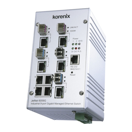
Hardware Introduction Dimension The industrial 9-port Gigabit managed Switch dimension is: 95mm x 167.65mm x 127.2mm (W x H x D), w/o DIN Rail 95mm x 167.65mm x 146.9mm (W x H x D), w/o DIN Rail Clip... - Page 10 Front Panel Layout The front panel includes 10/100/1000Mbps Gigabit Ethernet ports, SFP slot, RS232 console port, Reset button and LEDs for system and port indication The LED function is decribed as following table: Function Behaviors Power 1,2 Indicates the power input status On: the input connector is on applying power.
- Page 11 Bottom View The bottom view of the the Industrial 9-port Gigabit Managed Switch consists of two terminal block connectors with two DC power inputs, one Digital Input (DI), one Relay Output (DO) and one Chassis Grounding screw. Note: The unit intended to use vertical direction, with DIN-rail or wall-mount only.
-
Page 12: Wiring The Power Inputs
Wiring the Power Inputs Follow below steps to wire the Switch’s redundant DC power inputs. Insert positive and negative wires into V+ and V- contacts respectively of the terminal block connector Tighten the wire-clamp screws to prevent DC wires from being loosened. Power 1 and Power 2 support power redundancy and polarity reverse protect function. - Page 13 Note 3: If the 2 power inputs are connected, the Switch will be powered from the highest connected voltage. The unit will alarm for loss of power, either PWR1 or PWR2. Note 4: To use the UL Listed LPS Power supply with output Rating 10.5-60 Vdc, minimum 2 A.
-
Page 14: Wiring Digital Input
Wiring Digital Input The Switch provides one digital input. It allows users to connect the termination units’ digital output and manage/monitor the status of the connected unit. The Digital Input pin can be pulled high or low; thus the connected equipments can actively drive these pins high or low. -
Page 15: Wiring Earth Ground
Wiring Earth Ground To ensure the system will not be damaged by noise or any electrical shock, we suggest you to make exact connection between the Switch and Earth Grounding system. On the bottom side of the Switch, there is one earth ground screw. Loosen the earth ground screw by screw drive;... -
Page 16: Wiring Gigabit Ethernet Rj-45 Ports
Wiring Gigabit Ethernet RJ-45 Ports The Ethernet Switch adopts 9 ports RJ-45 connectors which support 10/100Mbps Half/Full duplex, 1000Mbps full duplex with auto MDI/MDI-X functions and auto negotiation; there are 5 in 9 ports RJ-45 are combo with SFP socket which supports optical fiber communication that can support 100Mbps and 1000Mbps SFP Transceiver with Digital Diagnostic Monitor (DDM) feature to achieves fiber signal quality control. -
Page 17: Wiring Combo Ports - Sfp
SFP ports combo with gigabit Ethernet RJ-45 ports. The speed of the SFP port supports 100Base-FX and 1000Base-SX/LX and accepts standard MINI GBIC SFP transceiver. For the system reliability, Korenix recommends using the Korenix certificated Gigabit SFP Transceiver, especially the DDM function. Korenix‘s DDM type of SFP transceiver have modified with higher accuracy. -
Page 18: Din-Rail Mounting Installation
The DIN rail clip supports EN50022 standard. In the diagram following includes the dimension of EN50022 DI rail for your refer. 1. Use the screws to attach DIN-Rail clip to the real panel of JetNet 6059G. 2. To remove DIN-Rail clip, reverse step 1. -
Page 19: Wall-Mounting Installation
2.10 Wall-Mounting Installation Follow the steps below to install the Switch with the wall mounting plate. 1. To remove DIN-Rail clip from Switch, loosen the screws from DIN-Rail clip. 2. Place the wall mounting plate on the rear panel of Switch. 3. - Page 20 screw and tight the wall-mount kit onto the rear side of the Switch. The specification of screw is M3 in 6 mm length.
-
Page 21: Preparation For Management
3 Preparation for Management The Industrial Managed Gigabit Switch provides both in-band and out-band configuration methods. You can configure the switch via RS232 console port via serial cable attached in the package if you don’t attach your admin PC to your network, or if you lose network connection to the target . -
Page 22: Preparation For Serial Console
Preparation for Serial Console In the shipping package, it has attached one RS-232 DB-9 to RJ-45 console cable. Please attach RS-232 DB-9 connector to your PC COM port, connect RJ-45 to the Console port of the Managed Switch. If you lose the cable, please follow the console cable PIN assignment to find one (Refer to session 2.8), or contact your sales representative too purchase a new cable. -
Page 23: Preparation For Web Interface
Interface for web management. 3.2.1 Web Interface Korenix web management page is developed by JAVA. It allows you to use a standard web-browser such as Microsoft IE, or Mozilla, to configure and interrogate the switch from anywhere on the network. - Page 24 Click on Enter or OK. Welcome page of the web-based management interface will then appear. English style Web UI 簡體中文 瀏覽器頁面 Once you enter the web-based management interface, you can freely change the JetNet’s IP address to fit your network environment. Note 1: IE 5.0 or later versions do not allow Java applets to open sockets by default.
- Page 25 3.2.2 Secured Web Interface The embedded Web Server also provides secured management HTTPS login. All the configuration commands will be secured and will be hard for the hackers to sniff the login password and configuration commands. Launch the web browser and Login. Launch the web browser (Internet Explorer or Mozilla Firefox) on the PC.
-
Page 26: Preparation For Telnet Console
Preparation for Telnet Console 3.3.1 Telnet The Managed Switch also supports Telnet console and with telnet security feature- SSH. You can connect to the switch by Telnet and the command lines are the same as what you see by RS232 console port. Below are the steps to open Telnet connection to the switch. - Page 27 1. Open SSH Client/PuTTY In the Session configuration, enter the Host Name (IP Address of your JetNet Switch) and Port number (default = 22). Choose the “SSH” protocol. Then click on “Open” to start the SSH session console. 2. After click on Open, then you can see the cipher information in the popup screen.
- Page 28 4. Type the Login Name and its Password. The default Login Name and Password are admin / admin. All the commands you see in SSH are the same as the CLI commands you see via RS232 console. The next chapter will introduce in detail how to use command line to configure the switch...
-
Page 29: Feature Configuration
4 Feature Configuration This chapter explains how to configure the Switch’s software features. There are four ways to access the switch: Serial console, Telnet, Web browser and SNMP. The Industrial Managed Switch provides both in-band and out-band configuration methods. You can configure the switch via RS232 console cable if you don’t attach your admin PC to your network, or if you lose the network connection to your Switch. -
Page 30: Command Line Interface Introduction
Command Line Interface Introduction The Command Line Interface (CLI) is the user interface to the switch’s embedded software system. You can view the system information, show the status, configure the switch and receive a response back from the system by keying in a command. There are some different command modes. - Page 31 Global Configuration Mode: Press configure terminal in privileged EXEC mode. You can then enter global configuration mode. In global configuration mode, you can configure all the features that the system provides you. Type interface IFNAME/VLAN to enter interface configuration mode, type “exit “...
- Page 32 Available command lists of the global configuration mode. Switch(config)# interface gi1 Switch(config-if)# acceptable Configure 802.1Q acceptable frame types of a port. auto-negotiation Enable auto-negotiation state of a given port description Interface specific description duplex Specify duplex mode of operation for a port End current mode and change to enable mode exit Exit current mode and down to previous mode...
- Page 33 Summary of the 5 command modes Command Main Function Enter and Exit Method Prompt Mode User EXEC This is the first level of access. Enter: Login successfully Switch> User can ping, telnet remote Exit: exit to logout. device, and show some basic Next mode: Type “enable”...
- Page 34 Here are some useful commands for you to see these available commands. Save your time in typing and avoid typing error. ? To see all the available commands in this mode. It helps you to see the next command you can/should type as well. Switch(config)# interface ? IFNAME Interface's name vlan...
-
Page 35: Basic Setting
Basic Setting The Basic Setting group provides you to configure switch information, IP address, User’s name/Password of the system. It also allows you to do firmware upgrade, backup and restore configuration, reload factory default, and reboot the system. Following commands are included in this group: 4.2.1 Switch Setting 4.2.2 Admin Password 4.2.3 IP Configuration... - Page 36 mail address or other information of the administrator. The available characters you can input are 64. System OID: The SNMP object ID of the switch. You can follow the path to find its private MIB in MIB browser. (Note: When you attempt to view private MIB, you should compile private MIB files into your MIB browser first.) System Description: Industrial Management Ethernet Switch is the name of this product.
- Page 37 4.2.3 IP Configuration This function allows users to configure the switch’s IP address settings The JetNet Switch supports IPv4 and IPv6 dual stack mechanism and able to run IPv4 and IPv6 in parallel and independent of each other to supports graduful migration of endpoints networks, and application.
- Page 38 Default Gateway: You can assign the gateway for the switch here. The default gateway is 192.168.10.254. Note: In CLI, we use 0.0.0.0/0 to represent for the default gateway. Once you finish the configuration, please click on Apply to apply your setting into system.
- Page 39 4.2.4 Time Setting Time Setting source allow user to set the time manually or through NTP server. Network Time Protocol (NTP) is used to synchronize computer clocks on the internet. You can configure NTP settings here to synchronize the clocks of several switches on the network.
- Page 40 IEEE 1588: select the PTP State to enable this function and select one operating mode for the precision time synchronizes. Auto mode: the switch performs PTP Master and slave mode (Bindary mode) Master mode: switch performs PTP Master only. Slave mode: switch performs PTP slave only. Time-zone: Select the time zone where the switch is located.
- Page 41 24 (GMT-01:00) Cape Verde Is. 25 (GMT) Casablanca, Monrovia 26 (GMT) Greenwich Mean Time: Dublin, Edinburgh, Lisbon, London 27 (GMT+01:00) Amsterdam, Berlin, Bern, Rome, Stockholm, Vienna 28 (GMT+01:00) Belgrade, Bratislava, Budapest, Ljubljana, Prague 29 (GMT+01:00) Brussels, Copenhagen, Madrid, Paris 30 (GMT+01:00) Sarajevo, Skopje, Sofija, Vilnius, Warsaw, Zagreb 31 (GMT+01:00) West Central Africa 32 (GMT+02:00) Athens, Istanbul, Minsk 33 (GMT+02:00) Bucharest...
- Page 42 Daylight Saving Start and Daylight Saving End: the time setting allows user to selects the week that monthly basis, and sets the End and Start time individually. Once you finish those configurations, click on Apply to apply your configuration. 4.2.5 DHCP Server You can select to Enable or Disable DHCP Server function.
- Page 43 network device. Add or remove an IP address from the Excluded Address List by clicking Add or Remove. Manual Binding: the Managed Switch provides a MAC address and IP address binding and removing function. You can type in the specified IP and MAC address, and then click Add to add a new MAC&IP address binding rule for a specified link partner, like PLC or any device without DHCP client function.
- Page 44 allows user assign specified IP address to specified port that DHCP client presented; and the DHCP server only offer the predefined IP address to the DHCP client. DHCP Leased Entries: the Managed Switch provides an assigned IP address list for user check. It will show the MAC and IP address that was assigned by Managed Switch.
- Page 45 Relay policy drop: Drops the option 82 field and do not add any option 82 field information into the packet. Relay policy keep: Keeps the original option 82 field and forwards packet to DHCP server. Relay policy replace: Replaces the existing option 82 field and adds new value into DHCP option 82 field.
- Page 46 Technical Tip: Default Configuration File: The switch provides the default configuration file in the system. You can use Reset button, Reload command to reset the system. Running Configuration File: The switch’s CLI allows you to view the latest settings running by the system. The information shown here is the settings you set up but haven’t saved to flash.
- Page 47 Type the IP address of TFTP Server IP. Then click on Backup/Restore. Note: point to the wrong file will cause the entire configuration missed...
- Page 48 4.2.7 Firmware Upgrade In this section, you can update the latest firmware for your switch, and also get latest version firmware from service Web site. The new firmware may include new features, bug fixes or other software changes. We’ll also provide the release notes for the update as well.
- Page 49 Click on Folder icon to select the target firmware file you want to upgrade. Figure 4.2.7.3 Firmware Upgrade – TFTP Server mode. Type the IP address of TFTP Server and Firmware File Name. Then click on Upgrade to start the process. After finishing transmitting the firmware, the system will copy the firmware file and replace the firmware in the flash.
- Page 50 4.2.8 Factory Default In this section, you can reset all the configurations of the switch to default setting. Click on Reset the system will then reset all configurations to default setting. The system will show you popup message window after finishing this command.
- Page 51 4.2.9 System Reboot System Reboot allows you to reboot the device. Some of the feature changes require you to reboot the system. Click on Reboot to reboot your device. Note: Remember to click on Save button to save your settings. Otherwise, the settings you made will be gone when the switch is powered off.
- Page 52 Switch(config)# hostname System Name WORD Network name of this system Switch(config)# hostname JN6059G SWITCH(config)# SWITCH(config)# snmp-server location Taipei System Location SWITCH(config)# snmp-server contact korecare@korenix.com System Contact SWITCH# show snmp-server name Display SWITCH# SWITCH# show snmp-server location Taipei SWITCH# show snmp-server contact korecare@korenix.com...
- Page 53 ip route 0.0.0.0/0 192.168.10.254/24 Time Setting SWITCH(config)# ntp peer NTP Server enable disable primary secondary SWITCH(config)# ntp peer primary IPADDR SWITCH(config)# ntp peer primary 192.168.10.120 SWITCH(config)# clock timezone 26 Time Zone Sun Jan 1 04:13:24 2006 (GMT) Greenwich Mean Time: Dublin, Edinburgh, Lisbon, London Note: By typing clock timezone ?, you can see the timezone list.
- Page 54 Switch(config-dhcp)# ip dhcp relay information option Enable DHCP Relay policy Switch(config-dhcp)# ip dhcp relay information policy replace drop Relay Policy keep Drop/Keep/Replace option82 field replace Switch# show ip dhcp server statistics Show DHCP server Switch# show ip dhcp server statistics information DHCP Server ON Address Pool 1...
- Page 55 Reload OK! Switch# reboot System Reboot Switch# reboot Reboot...
-
Page 56: Port Configuration
Port Configuration Port Configuration group enables you to enable/disable port state, or configure port auto-negotiation, speed, and duplex, flow control, rate limit control and port aggregation settings. It also allows you to view port status and aggregation information. Following commands are included in this group: 4.3.1 Port Control 4.3.2 Port Status 4.3.3 Rate Control... - Page 57 of this port. Below are the selections you can choose: Gigabit Ethernet Port 1~9: (gi1~gi9) : AutoNegotiation, 10M Full Duplex(10 Full), 10M Half Duplex(10 Half), 100M Full Duplex(100 Full), 100M Half Duplex(100 Half), 1000M Full Duplex(1000 Full), 1000M Half Duplex(1000 Half).
- Page 58 4.3.2 Port Status Port Status shows you current port status. In the firmware version 2.2, it supports Small Form Factory (SFP) fiber transceiver with Digital Diagnostic Monitoring (DDM) function that provides real time information of SFP transceiver and allows user to diagnostic the optical fiber signal received and launched.
- Page 59 Unknown info, it may mean that the vendor doesn’t provide their information or that the information of their transceiver can’t be read. 2. if the plugged DDM SFP transceiver is not certified by Korenix, the DDM function will not be supported. But the communication will not disable.
- Page 60 IEEE standard, 802.3ad. The aggregated ports can interconnect to the other switch which also supports Port Trunking. Korenix Supports 2 types of port trunking. One is Static Trunk, the other is 802.3ad. When the other end uses 802.3ad LACP, you should assign 802.3ad LACP to the trunk. When the other end uses non-802.3ad, you can then use Static Trunk.
- Page 61 Aggregation Setting Trunk Size: The switch can support up to 4 trunk groups. Each trunk group can support up to 8 member ports. The member ports should use same speed and link duplex mode. Group ID: Group ID is the ID for the port trunking group.
- Page 62 LACP Timeout: The LACPDU is generated and continue transmit within the LACP group. The interval time of the LACPDU Long timeout is 30 sec, this is default setting. The LACPDP Short timeout is 1 sec, the command to change from Long to Short is only applied to the CLI, and the web GUI doesn’t support this command.
- Page 63 4.3.5 Command Lines for Port Configuration Feature Command Line Port Control Switch(config-if)# shutdown -> Disable port state Port Control – State Port1 Link Change to DOWN interface fastethernet1 is shutdown now. Switch(config-if)# no shutdown -> Enable port state Port1 Link Change to DOWN Port1 Link Change to UP interface fastethernet1 is up now.
- Page 64 Operating Status : Connected Duplex : Full Speed : 100 Flow Control :off Default Port VLAN ID: 1 Ingress Filtering : Disabled Acceptable Frame Type : All Port Security : Disabled Auto Negotiation : Disable Loopback Mode : None STP Status: forwarding Default CoS Value for untagged packets is 0.
- Page 65 Note: The interface list is gi1-9 Note: different speed port can’t be aggregated together. SWITCH(config-if)# lacp LACP – Port Setting port-priority LACP priority for physical interfaces timeout assigns an administrative LACP timeout SWITCH(config-if)# lacp port-priority <1-65535> Valid port priority range 1 - 65535 (default is 32768) SWITCH(config-if)# lacp timeout Long/Short Timeout...
-
Page 66: Network Redundancy
Network Redundancy It is critical for industrial applications that network remains non-stop. The Switch’s firmware supports IEEE 802.31D:2004 STP/RSTP, IEEE 802.1s Multiple Spanning Tree, Multiple Super Ring (M.S.R.) and backwad compatible with Legacy Super Ring. The M.S.R. technology is patented 3 generation ring technology which includes several of network redundant methods to supports a reliable, stable network transmission. - Page 67 4.4.9 Command Lines for Network Redundancy 4.4.1 STP Configuration This page allows select the STP mode and configuring the global STP/RSTP Bridge Configuraiton. The STP mode includes the STP, RSTP, MSTP and Disable. Please select the STP mode for your system first. The default mode is RSTP enabled. Afte select the STP or RSTP mode;...
-
Page 68: Bridge Configuration
Bridge Configuration Bridge Address: This shows the switch’s MAC address. Priority (0-61440): RSTP uses bridge ID to determine the root bridge, the bridge with the highest bridge ID becomes the root bridge. The bridge ID is composed of bridge priority and bridge MAC address. So that the bridge with the highest priority becomes the highest bridge ID. - Page 69 4.4.2 STP Port Configuration The STP port configuration allows you to configure the port parameter after enabled STP function, and also supports per port STP enable/disable function here. Port Configuration Select the port you want to configure and you will be able to view current setting and status of the port.
- Page 70 Once you finish your configuration, click on Apply to save your settings 4.4.3 RSTP Info This page allows you to see the information of the root switch and port status Root Information: You can see root Bridge ID, Root Priority, Root Port, Root Path Cost and the Max Age, Hello Time and Forward Delay of BPDU sent from the root switch.
- Page 71 maintain the correct spanning tree and operate effectively. One VLAN can be mapped to a Multiple Spanning Tree Instance (MSTI). The maximum Instance of the managed Switch supports is 16, range from 0-15. The MSTP builds a separate Multiple Spanning Tree (MST) for each instance to maintain connectivity among each of the assigned VLAN groups.
- Page 72 To configure the MSTP setting, the STP Mode of the STP Configuration page should be changed to MSTP mode first. After enabled MSTP mode, then you can go to the MSTP Configuraiton page MSTP Region Configuration This page allows configure the Region Name and its Revision, mapping the VLAN to Instance and check current MST Instance configuration.
- Page 73 Instance ID: Select the Instance ID, the available number is 1-15. VLAN Group: Type the VLAN ID you want mapping to the instance. Instance Priority: Assign the priority to the instance. After finish your configuration, click on Add to apply your settings. Current MST Instance Configuration This page allows you to see the current MST Instance Configuration you added.
- Page 74 Path Cost: Enter a number between 1 and 200,000,000. This value represents the “cost” of the path to the other bridge from the transmitting bridge at the specified port. Priority: Enter a value between 0 and 240, using multiples of 16. This is the value that decides which port should be blocked by priority in a LAN.
- Page 75 Click “Reload“ to reload the MSTP information display...
- Page 76 4.4.7 Multiple Super Ring (MSR) (The same as 4.4.31 of previous version manual.) The most common industrial network redundancy is to form a ring or loop. Typically, the managed switches are connected in series and the last switch is connected back to the first one. In such connection, you can implement the Multiple Super Ring technology to get fatest recovery performance.
- Page 77 “RingID”. Version: The version of Ring can be changed here. There are three modes to choose: Rapid Super Ring as default; Super ring for compatible with Korenix 1 general ring and Any Ring for compatible with other version of rings.
- Page 78 Dual Homing will smartly choose the fastest link for primary link and block the other link to avoid loop. If the primary link failed, Rapid Dual Homing will automatically forward the secondary link for network redundant. Of course, if there are more connections, they will be standby links and recover one of then if both primary and secondary links are broken.
- Page 79 4.4.8 Ring Info This page shows the RSR information. ID: Ring ID. Version: which version of this ring, this field could be Rapid Super Ring, Super Ring, or Any Ring Role: This Switch is RM or nonRM Status: If this field is Normal which means the redundancy is approved. If any one of the link in this Ring is broken, then the status will be Abnormal.
- Page 80 Region Configuration Region Name: Switch(config-mst)# name NAME the name string Switch(config-mst)# name korenix Region Revision: Switch(config-mst)# revision <0-65535> the value of revision Switch(config-mst)# revision 65535 Mapping Instance to Switch(config-mst)# instance VLAN (Ex: Mapping <1-15>...
- Page 81 VLANMAP target vlan number(ex.10) or range(ex.1-10) Switch(config-mst)# instance 1 vlan 2 Display Current MST Switch(config-mst)# show current Configuraion Current MST configuration Name [korenix] Revision 65535 Instance Vlans Mapped -------- -------------------------------------- 1,4-4094 ------------------------------------------------ Config HMAC-MD5 Digest: 0xB41829F9030A054FB74EF7A8587FF58D ------------------------------------------------ Remove Region Switch(config-mst)# no...
- Page 82 RSTP System RSTP Setting The mode should be rst, the timings can be configured in global settings listed in above. Port Configuration Mode Port Configuraiton Switch(config)# interface fa1 Switch(config-if)# spanning-tree bpdufilter a secure BPDU process on edge-port interfcae bpduguard a secure response to invalid configurations(received BPDU sent by self) cost change an interafce's spanning-tree port path cost...
- Page 83 TCN : sent 0 , received 0 Forwarding-State Transmit count Message-Age Expired count MSTP Information MSTP Configuraiton Switch# show spanning-tree mst configuration Current MST configuration (MSTP is Running) Name [korenix] Revision 65535 Instance Vlans Mapped -------- -------------------------------------- 1,4-4094 ------------------------------------------------ Config HMAC-MD5 Digest: 0xB41829F9030A054FB74EF7A8587FF58D...
- Page 84 MST01 0012.77ee.eeee 32768 MST02 0012.77ee.eeee 32768 MSTP Instance Switch# show spanning-tree mst 1 Information ###### MST01 vlans mapped: 2 Bridge address 0012.77ee.eeee priority 32768 (sysid 1) Root this switch for MST01 Port Role State Cost Prio.Nbr Type ------ ---------- ---------- -------- ---------- ------------------ fa1 Designated Forwarding 200000 128.1...
- Page 85 Switch(config-multiple-super-ring)# rapid-dual-homing port IFLIST Interface name, ex: fastethernet1 or gi8 auto-detect up link auto detection IFNAME Interface name, ex: fastethernet1 or gi8 Switch(config-multiple-super-ring)# rapid-dual-homing port fa3,fa5-6 set Rapid Dual Homing port success. Note: auto-detect is recommended for dual Homing.. Ring Info Ring Info Switch# show multiple-super-ring [Ring ID] [Ring1] Ring1...
-
Page 86: Vlan
Figure 4.5-1 802.1Q VLAN QinQ In JetNet6059G firmware V1.1, Korenix release extended VLAN feature, QinQ. The QinQ is originally designed to expand the number of VLANs by adding a tag to the 802.1Q packets. - Page 87 The original VLAN is usually identified as Customer VLAN (C-VLAN) and the new added tag - as Service VLAN(S-VLAN). By adding the additional tag, QinQ increases the possible number of VLANs. After QinQ enabled, the managed Switch can reach up to 256x256 VLANs. With different standard tags, it also improves the network security.
- Page 88 PVID: The abbreviation of the Port VLAN ID. Enter port VLAN ID here. PVID allows the switches to identify which port belongs to which VLAN. To keep things simple, it is recommended that PVID is equivalent to VLAN IDs. The values of PVIDs are from 0 to 4095. But, 0 and 4095 are reserved. You can’t input these 2 PVIDs.
- Page 89 VLAN’s Egress list. If it is, the frame can be processed. If it’s not, the frame would be dropped. After 802.1Q Tunnel or 802.1Q Tunnel Uplink is enabled, the Ingress Filtering can not be configured. 4.5.2 VLAN Configuration In this page, you can assign Management VLAN, create the static VLAN, and assign the Egress rule for the member ports of the VLAN.
- Page 90 ID). Figure 4.5.2-2 The steps to create a new VLAN: Type VLAN ID and NAME, and press Add to create a new VLAN. Then you can see the new VLAN in the Static VLAN Configuration table. Refer to Figure 4.5-5 After created the VLAN, the status of the VLAN will remain in Unused until you add ports to the VLAN.
- Page 91 Figure 4.5.2-4 Configure Egress rule of the ports. -- : Not available U: Untag: Indicates that egress/outgoing frames are not VLAN tagged. T : Tag: Indicates that egress/outgoing frames are to be VLAN tagged. Steps to configure Egress rules: Select the VLAN ID. Entry of the selected VLAN turns to light blue.
- Page 92 GVRP Protocol: Allow user to enable/disable GVRP globally. State: After enable GVRP globally, here still can enable/disable GVRP by port. Join Timer: Controls the interval of sending the GVRP Join BPDU. An instance of this timer is required on a per-Port, per-GARP Participant basis Leave Timer: Control the time to release the GVRP reservation after received the GVRP Leave BPDU.
- Page 93 Feature Command Line VLAN Port Configuration Port Interface Switch# configure terminal Configuraion Switch(config)# interface gi5 interface name Switch(config-if)# VLAN Port PVID Switch(config-if)# switchport trunk native vlan 2 Set port default vlan id to 2 success QinQ Tunnel Mode Switch(config-if)# switchport dot1q-tunnel mode Set the interface as an IEEE 802.1Q tunnel mode 802.1Q Tunnel = Switch(config-if)# switchport dot1q-tunnel mode...
- Page 94 interface vlan1 ip address 192.168.10.8/24 no shutdown QinQ Information – Switch# show dot1q-tunnel 802.1Q Tunnel dot1q-tunnel mode port 1 : normal port 2 : normal port 3 : normal port 4 : normal port 5 : access port 6 : uplink port 7 : normal port 8 : normal port 9 : normal...
- Page 95 Switch(config-if)# Switch(config-if)# description this is the VLAN 2 Switch(config-if)# no description ->Delete the description. IP address of the VLAN Switch(config)# interface vlan 2 Switch(config-if)# Switch(config-if)# ip address 192.168.10.18/24 Switch(config-if)# no ip address 192.168.10.8/24 ->Delete the IP address Create multiple VLANs Switch(config)# interface vlan 5-10 (VLAN 5-10) Shut down VLAN...
-
Page 96: Private Vlan
Private VLAN The private VLAN helps to resolve the primary VLAN ID shortage, client ports’ isolation and network security issues. The Private VLAN provides primary and secondary VLAN within a single switch. Primary VLAN: The uplink port is usually the primary VLAN. A primary VLAN contains promiscuous ports that can communicate with lower Secondary VLANs. - Page 97 Community: The VLAN is the Community VLAN. The member ports of the VLAN can communicate with each other. 4.6.2 PVLAN Port Configuration PVLAN Port Configuration page allows configure Port Configuration and Private VLAN Association. Private VLAN Association Secondary VLAN: After the Isolated and Community VLAN Type is assigned in Private VLAN Configuration page, the VLANs are belonged to the Secondary VLAN and displayed here.
- Page 98 For example: 1. VLAN Create: VLAN 2-5 are created in VLAN Configuration page. 2. Private VLAN Type: VLAN 2-5 has its Private VLAN Type configured in Private VLAN Configuration page. VLAN 2 is belonged to Primary VLAN. VLAN 3-5 are belonged to secondary VLAN (Isolated or Community). 3.
- Page 99 4.6.3 Private VLAN Information This page allows you to see the Private VLAN information. 4.6.4 CLI Command of the PVLAN Command Lines of the Private VLAN configuration Feature Command Line Private VLAN Configuration Create VLAN Switch(config)# vlan 2 vlan 2 success Switch(config-vlan)# End current mode and change to enable mode exit...
- Page 100 <cr> Private VLAN Port Configuraiton Go to the port Switch(config)# interface (port_number, ex: gi9) configuraiton Switch(config-if)# switchport private-vlan host-association Set the private VLAN host association mapping map primary VLAN to secondary VLAN Private VLAN Port Type Switch(config-if)# switchport mode private-vlan Set private-vlan mode Switch(config-if)# switchport mode private-vlan host Set the mode to private-vlan host...
- Page 101 Host List Switch# show vlan private-vlan port-list Ports Mode Vlan ----- ----------- ---- normal normal normal normal normal normal host host host promiscuous 2 Running Config Switch# show run Information Building configuration... Current configuration: hostname Switch vlan learning independent vlan 1 Private VLAN Type vlan 2 private-vlan primary...
-
Page 102: Traffic Prioritization
switchport private-vlan mapping 2 add 3-5 ……… …….. Traffic Prioritization Quality of Service (QoS) provides traffic prioritization mechanism which allows users to deliver better service to certain flows. QoS can also help to alleviate congestion problems and ensure high-priority traffic is delivered first. - Page 103 In JetNet management switch, users can freely assign the mapping table or follow the suggestion of the 802.1p standard. Korenix uses 802.1p suggestion as default values. You can find CoS values 1 and 2 are mapped to physical Queue 0, the lowest queue.
- Page 104 4.7.3 DSCP-Queue Mapping This page is to change DSCP values to Physical Queue mapping table. Since the switch fabric of JetNet only supports 4 physical queues, Lowest, Low, Middle and High. Users should therefore assign how to map DSCP value to the level of the physical queue. In JetNet, users can freely change the mapping table to follow the upper layer 3 switch or routers’...
- Page 105 Port Setting – CoS Switch(config)# interface fa1 (Default Port Priority) Switch(config-if)# qos cos DEFAULT-COS Assign an priority (7 highest) Switch(config-if)# qos cos 7 The default port CoS value is set 7 ok. Note: When change the port setting, you should Select the specific port first.
- Page 106 Note: Format: qos cos-map priority_value queue_value Map CoS 0 to Queue 1 Switch(config)# qos cos-map 0 1 The CoS to queue mapping is set ok. Map CoS 1 to Queue 0 Switch(config)# qos cos-map 1 0 The CoS to queue mapping is set ok. Map CoS 2 to Queue 0 Switch(config)# qos cos-map 2 0 The CoS to queue mapping is set ok.
-
Page 107: Multicast Filtering
Multicast Filtering For multicast filtering, the managed Switch uses IGMP Snooping technology. IGMP (Internet Group Management Protocol) is an Internet Protocol that provides a way for internet device to report its multicast group membership to adjacent routers. Multicasting allows one computer on the internet to send data to a multitude of other computers that have identified themselves as being interested in receiving the originating computers data. - Page 108 IGMP Snooping, you can select Enable or Disable here. After enabling IGMP Snooping, you can then enable IGMP Snooping for specific VLAN. You can enable IGMP Snooping for some VLANs so that some of the VLANs will support IGMP Snooping and others won’t. To assign IGMP Snooping to VLAN, please select the checkbox of VLAN ID or select "Select All"...
- Page 109 4.8.2 IGMP Query This page allows users to configure IGMP Query feature. Since the Switch can only be configured by member ports of the management VLAN, IGMP Query can only be enabled on the management VLAN. If you want to run IGMP Snooping feature in several VLANs, you should notice that whether each VLAN has its own IGMP Querier first.
- Page 110 The Unknown Multicasting filtering function supports 3 forwarding modes, send to query port, send to all ports and discard. Send to Query Ports: The device sends the packets with an unknown MAC/IP Multicast address to query ports. Send to All Ports: The device sends the packets with an unknown MAC/IP Multicast address to all ports.
- Page 111 State: The state of the GMRP operation on this port. The value enabled indicates that the GMRP is enabled on this port, as long as the GMRP Protocol is also enabled for this device. When disabled, but the GMRP Protocol is still enabled for the device, GMRP is disabled on this port.
- Page 112 Display Switch# sh ip igmp interface vlan1 enabled: Yes version: IGMPv2 query-interval: 125s query-max-response-time: 10s Switch# show running-config …. interface vlan1 ip address 192.168.10.17/24 ip igmp no shutdown ……. Force filtering Enable Force filtering Switch(config)# mac-address-table multicast filtering Filtering unknown multicast addresses ok! Disable Force filtering Switch(config)# no mac-address-table multicast filtering Flooding unknown multicast addresses ok!
-
Page 113: Snmp
SNMP Simple Network Management Protocol (SNMP) is a protocol used for exchanging management information between network devices. SNMP is a member of the TCP/IP protocol suite. The Switch supports SNMP v1 and v2c and V3. An SNMP managed network consists of two main components: agents and a manager. - Page 114 4.9.2 SNMP V3 Profile SNMP v3 can provide more security functions when the user performs remote management through SNMP protocol. It delivers SNMP information to the administrator with user authentication; all of data between Switch and the administrator are encrypted to ensure secure communication Security Level: Here the user can select the following levels of security: None, User Authentication, and Authentication with privacy.
- Page 115 IP, Community name, and trap Version V1 or V2. After configuration, you can see the change of the SNMP pre-defined standard traps and Korenix pre-defined traps. The pre-defined traps can be found in Korenix private MIB. 4.9.4 CLI Commands of the SNMP...
- Page 116 Read Write Community Switch(config)# snmp-server community private rw community string add ok SNMP Trap Enable Trap Switch(config)# snmp-server enable trap Set SNMP trap enable ok. SNMP Trap Server IP Switch(config)# snmp-server host 192.168.10.33 without specific SNMP trap host add OK. community name SNMP Trap Server IP Switch(config)# snmp-server host 192.168.10.33 version 1...
-
Page 117: Security
4.10 Security The Switch provides several security features for you to secure your connection. The features include Port Security and IP Security. Following commands are included in this group: 4.10.1 Port Security 4.10.2 IP Security 4.10.3 IEEE 802.1x 4.10.4 CLI Commands of the Security 4.10.1 Port Security Port Security feature allows you to stop the MAC address learning for specific port. - Page 118 Once you finish configuring the settings, click on Apply / Add to apply your configuration. 4.10.2 IP Security In IP Security section, you can set up specific IP addresses to grant authorization for management access to this JetNet via a web browser or Telnet.
- Page 119 4.10.3 802.1x 802.1x Configuration IEEE 802.1X is the protocol that performing authentication to obtain access to IEEE 802 LANs. It is port-base network access control. With the function, Switch could control which connection is available or not. System AuthControl: To enable or disable the 802.1x authentication. Authentication Method: Radius is an authentication server that provide key for authentication, with this method, user must connect switch to server.
- Page 120 802.1x Port Configuration After the configuration of Radius Server or Local user list, user also need configure the authentication mode, authentication behavior, applied VLAN for each port and permitted communication. The following information will explain the port configuration. Port control: Force Authorized means this port is authorized; the data is free to in/out.
- Page 121 number is 1~65535. Quiet Period: When authentication failed, Switch will wait for a period and try to communicate with radius server again. Tx period: the time interval of authentication request. Supplicant Timeout: the timeout for the client authenticating Sever Timeout: The timeout for server response for authenticating. Once you finish configuring the settings, click on Apply to apply your configuration.
- Page 122 then enable the port security to stop new MAC learning. Disable Port Security Switch(config-if)# no switchport port-security Enable new MAC addresses learning and aging activities! Display Switch# show mac-address-table static Destination Address Address Type Vlan Destination Port ------------------- --------------- ------- ------------------------ 0012.7701.0101 Static IP Security...
- Page 123 Secondary RADIUS Server IP : 192.168.10.250 Secondary RADIUS Server Key : 5678 Secondary RADIUS Server Port : 1812 Secondary RADIUS Accounting Port : 1813 User name/password Switch(config)# dot1x username korenix passwd korenix vlan for authentication...
-
Page 124: Warning
4.11 Warning The Switch provides several types of Warning features for you to remote monitor the status of end devices or the change of your network. The features include Fault Relay, System Log and SMTP E-mail Alert. Following commands are included in this group: 4.11.1 Fault Relay 4.11.2 Event Selection 4.11.3 Syslog Configuration... - Page 125 (the Switch only supports one Digital or Low Input) The Fault relay configuration UI has shown as below: Relay 1: Show current relay state. If the relay is triggered, the event type will be marked with the symbol- . On the upper diagram, the replay is triggerd by port event –...
- Page 126 range of a period is 0-65535 seconds DI: monitoring the Digital input state.
- Page 127 4.11.2 Event Selection Event Types can be divided into two basic groups: System Events and Port Events. System Events are related to the overall function of the switch, whereas Port Events related to the activity of specific ports System Event Warning Event is sent when…..
- Page 128 Click on the select box to enable /disable the system event, and choice the port event type for monitoring, and then click the icon “Apply” to activate the monitoring functions. 4.11.3 SysLog Configuration System Log is useful to provide system administrator locally or remotely monitor switch events history.
- Page 129 Field Description SMTP Server IP Address Enter the IP address of the email Server Authentication Click on check box to enable password User Name Enter email Account name (Max.40 characters) Password Enter the password of the email account Confirm Password Re-type the password of the email account You can set up to 4 email addresses to receive email alarm from JetNet Rcpt E-mail Address 1...
-
Page 130: Cli Commands
4.11.5 CLI Commands Command Lines of the Warning configuration Feature Command Line Relay Output Relay Output Switch(config)# relay 1 DI state dry output ping ping failure port port link failure power power failure ring super ring failure Note: Select Relay 1 or 2 first, and then select the event types. - Page 131 Switch(config)# smtp-server server 192.168.10.100 admin@korenix.com SMTP Email Alert set Server: 192.168.10.100, Account: admin@korenix.com ok. Receiver mail Switch(config)# smtp-server receipt 1 korecare@korenix.com SMTP Email Alert set receipt 1: korecare@korenix.com ok. Authentication with Switch(config)# smtp-server authentication username admin username and password admin password...
- Page 132 Disable Authentication Switch(config)# no smtp-server authentication SMTP Email Alert set Authentication disable ok. Dispaly Switch# sh smtp-server SMTP Email Alert is Enabled Server: 192.168.10.100, Account: admin@korenix.com Authentication: Enabled Username: admin, Password: admin SMTP Email Alert Receipt: Receipt 1: korecare@korenix.com Receipt 2:...
-
Page 133: Monitor And Diag
4.12 Monitor and Diag The Switch provides several types of features for you to monitor the status of the switch or diagnostic for you to check the problem when encountering problems related to the switch. The features include MAC Address Table, Port Statistics, Port Mirror, Event Log and Ping. - Page 134 Click on Remove to remove the static Unicast/Multicast MAC address. Click on Reload to refresh the table. New learnt Unicast/Multicast MAC address will be updated to MAC address table. 4.12.2 Port Statistics In this page, you can view operation statistics for each port. The statistics that can be viewed include Link Type, Link State, Rx Good, Rx Bad, Rx Abort, Tx Good, Tx Bad and Collision.
- Page 135 4.12.3 Port Mirroring Port mirroring (also called port spanning) is a tool that allows you to mirror the traffic from one or more ports onto another port, without disrupting the flow of traffic on the original port. Any traffic that goes into or out of the Source Port(s) will be duplicated at the Destination Port.
- Page 136 Once you finish configuring the settings, click on Apply to apply the settings. 4.12.4 Event Log In the 4.10.3, we have introduced System Log feature. When System Log Local mode is selected, the Switch will record occurred events in local log table.
- Page 137 segment.
- Page 138 4.12.6 Ping Utility This page provides Ping Utility for users to ping remote device and check whether the device is alive or not. Type Target IP address of the target device and click on Start to start the ping. After few seconds, you can see the result in the Result field.
-
Page 139: Port Mirroring
Destination Address Address Type Vlan Destination Port ------------------- --------------- ------- ------------------------ 000f.b079.ca3b Dynamic 0012.7701.0386 Dynamic 0012.7710.0101 Static 0012.7710.0102 Static 0012.77ff.0100 Management ***** MULTICAST MAC ADDRESS ***** Vlan Mac Address Status Ports ---- --------------- ---- ------- -------------------------- 0100.5e40.0800 0100.5e7f.fffa gi4,gi6 Show MAC Address Switch# show mac-address-table dynamic Table –... - Page 140 Transmitted traffic Switch(config)# mirror source gi1-2 both Mirror source gi1-2 both set ok. Note: Select source port list and TX/RX/Both mode. Select Destination Port Switch(config)# mirror destination gi6 both Mirror destination gi6 both set ok Display Switch# show mirror Mirror Status : Enabled Ingress Monitor Destination Port : gi6 Egress Monitor Destination Port : gi6 Ingress Source Ports :gi1,gi2,...
-
Page 141: Device Front Panel
4.12 Device Front Panel Device Front Panel command allows you to see LED status of the switch. You can see LED and link status of the Power, DO, DI, R.M. and Ports Feature On / Link UP Off / Link Down Other Power Green... -
Page 142: Save To Flash
4.13 Save to Flash Save Configuration allows you to save any configuration you just made to the Flash. Powering off the switch without clicking on Save Configuration will cause loss of new settings. After selecting Save Configuration, click on Save to Flash to save your new configuration. Command Lines: Feature Command Line... -
Page 143: Logout
4.14 Logout The switch provides 2 logout methods. The web connection will be logged out if you don’t input any command after 30 seconds. The Logout command allows you to manually logout the web connection. Click on Yes to logout, No to go back the configuration page. -
Page 144: Appendix
5 Appendix Product Specifications. Technology Standard IEEE 802.3 10Base-T Ethernet IEEE 802.3u 100Base-TX Fast Ethernet IEEE 802.3u 100Base-FX Fast Ethernet Fiber IEEE 802.3ab 1000Base-T IEEE 802.3z Gigabit Fiber IEEE 802.3x Flow Control and Back-pressure IEEE 802.1AB Link Layer Discovery Protocol (LLDP) IEEE 802.1p Class of Service (CoS) IEEE 802.1Q VLAN and GVRP IEEE 802.1D-2004 Rapid Spanning Tree Protocol (RSTP) -
Page 145: System Management
IP address SNMP MIB MIBII, Bridge MIB, Ethernet-like MIB, VLAN MIB, IGMP MIB, Korenix Private MIB Korenix Utility Supports JetView and JetView Pro with IEEE 802.1AB Link Layer Discovery Protocol (LLDP)for device finding and link topology... - Page 146 Network Redundancy Multiple Super Ring (MSR) New generation Korenix Ring Redundancy Technology, Includes Rapid Super Ring, Rapid Dual Homing, TrunkRing , MultiRing and backward compatible with legacy Super Ring...
-
Page 147: Power Requirements
Multiple Spanning Tree IEEE802.1s MSTP, each MSTP instance can include one or more VLANs. Supports multiple RSTP deployed in a VLAN or multiple VLANs The Loop protection enable the looping issue eliminates faster and Loop Protection prevents port looping caused by RSTP protocol. Interface Enclosure Port 10/100/1000TX: 9 x RJ-45... -
Page 148: Ordering Information
Free Fall IEC60068-2-32 with package Warranty Global 5 years Note-2: pending Note-3: Korenix’s internal testing Note-4: For the latest version specification, please contact your sales window or distributor. Ordering Information JetNet 6059G Industrial 9-port Gigabit Managed Ethernet Switch, 4 TX, 5 TX/SFP combo, -25~70°C operating temperature... - Page 149 RS-232 console Cable x1...
-
Page 150: Korenix Sfp Family
SFP transceivers when you constructing your network. Korenix will keep on certificating and updating the certificated SFP transceivers in Korenix web site and purchase list. You can refer to the web site to get the latest information about SFP transceivers. -
Page 151: Korenix Private Mib
Korenix provides many standard MIBs for users to configure or monitor the switch’s configuration by SNMP. But, since some commands can’t be found in standard MIB, Korenix provides Private MIB to meet up the need. Compile the private MIB file by your SNMP tool. You can then use it. -
Page 152: Modbus Tcp Protocol
Modbus TCP protocol The Modbus TCP is very similar to Modbus RTU, but transmists data within TCP/IP Data packets. It was developed in 1979 for industrial automatic communication system and have becomes a standard protocol for industrial communication for the transfer discrete analogi I/O devices or PLC systems. It defines a simple protocol data unit independent of the underlying data link layer. - Page 153 Volt/Current Transducer, network communication switch) which process information and sends the output data to the master using modbus TCP protocol. Korenix JetNet Switch operating as slave/server devices, while a typical master/client device is host computer running appropriate application software, like as SCADA / HMI system. The transction architecture like as the drawing following.
- Page 154 code to access device-dependent information. Modbus TCP function code is defined as below. Name Usage Read Coils Read the state of a digital output Read Input Status Read the state of a digital input Read holding register in 16-bits register Read Holding Register format Read Input Registers...
- Page 155 Data Type Description System Information 0x0000 16 words Vender Name = “Korenix” Word 0 Hi byte = ‘K’ Word 0 Lo byte = ‘o’ Word 1 Hi byte = ‘r’ Word 1 Lo byte = ‘e’ Word 2 Hi byte = ‘n’...
- Page 156 Word 3 Lo byte = ‘8’ Word 4 Lo byte = ‘2’ Word 4 Hi byte = ‘8’ Word 5 Lo byte = ‘G’ Word 5 Hi byte = ‘\0’ (other words = 0) 0x0020 128 words SNMP system name (string) 0x00A0 128 words SNMP system location (string)
- Page 157 Word 0 Lo byte = 0xA8 Word 1 Hi byte = 0x0A Word 1 Lo byte = 0x01 0x0302 2 words Subnet Mask 0x0304 2 words Default Gateway 0x0306 2 words DNS Server 0x0308 to 0x3FF 248 words Reserved address space (IPv6 or others) 0x0400 1 word 0x0000:Off...
- Page 158 0x0001:On 0xFFFF: unavailable 0x0414 to 0x041F 12 words Reserved address space 0x0420 1 word 0x0000:Off 0x0001:On 0x0421 1 word 0x0000:Off 0x0001:On 0x0422 1 word 0x0000:Off 0x0001:On 0x0423 1 word Port Information (32 Ports) 0x1000 to 0x11FF 16 words Port Description 0x1200 to 1 word Administrative Status...
- Page 159 0x0103: auto 1000 0x0104: auto 2500 0x0105: auto 10000 0x0100: auto 0xFFFF: unavailable 0x1280 to 1 word Flow Control 0x129F 0x0000: off 0x0001: on 0xFFFF: unavailable 0x12A0 to 1 word Default Port VLAN ID 0x12BF 0x0001-0xFFFF 0x12C0 to 1 word Ingress Filtering 0x12DF 0x0000: disable...
- Page 160 0x13BF 0x0000: disable 0x0001: enable 0x0002: auto 0xFFFF: unavailable 0x13C0 to 1 word Medium mode 0x13DF 0x0000: copper 0x0001: fiber 0x0002: none 0xFFFF: unavailable 0x13E0 to 288 words Reserved address space 0x14FF SFP Information (32 Ports) 0x1500 to 0x151F 1 word SFP Type 0x1520 to 0x153F 1 words...
- Page 161 0x217F 0x2180 to 2 words Undersize 0x21BF 0x21C0 to 2 words Fragments 0x21FF 0x2200 to 2 words Oversize 0x223F 0x2240 to 2 words Jabbers 0x227F 0x2280 to 2 words Disacrds 0x22BF 0x22C0 to 2 words Filtered frames 0x22FF 0x2300 to 2 words RxError 0x233F...
- Page 162 0x26FF 0x2700 to 2 words MultipleCollision 0x273F 0x2740 to 2 words ExcessiveCollision 0x277F 0x2780 to 2 words LateCollision 0x27BF 0x27C0 to 2 words Filtered 0x27FF 0x2800 to 0x283F 2 words FCSError 0x2840 to 447 words Reserved address space 0x29FF Number of frames received and transmitted with a length(in octets) 0x2A00 to 2 words 0x2A3F...
- Page 163 Set modbus TCP master Switch(config)# modbus master communicate session. <1-20> Max Modbus TCP Master Switch(config)# modbus master 2 set maximum modbus master up to 2; maximum support up to 20 modbus communicate sessions. Set modbus TCP listening Switch(config)# modbus port port port Listening Port Switch(config)# modbus port 502 ;...
-
Page 164: Revision History
Revision History Edition Date Modifications V 0.1 22,Oct,2010 New edittion39 Firmware version V0.1.39 with more system information, ex date of manufacture, serial number. V0.2 10-DEC,2010 Modify: 1. power input range 10.5~60V DC 2. relay contactor voltage: 1A / DC24V 3. modify interface name to gigaethernet 13-DEC,2010 1. -
Page 165: About Korenix
Less Time At Work! Fewer Budget on applications! The Korenix business idea is to let you spend less time at work and fewer budget on your applications. Do you really want to go through all the troubles but still end up with low quality products and lousy services? Definitely not! This is why you need Korenix.
Need help?
Do you have a question about the JetNet 6059G Series and is the answer not in the manual?
Questions and answers