
Related Manuals for Korenix JetNet 6910G-M12 Series


Summary of Contents for Korenix JetNet 6910G-M12 Series
- Page 1 Korenix JetNet 6910G-M12 Series Industrial Managed Ethernet Switch User Manual Manual v1.0 Aug, 2017 www.korenix.com...
- Page 2 Korenix JetNet 6910G-M12 Series Industrial Managed Ethernet Switch User Manual Copyright Notice Copyright 2006-2017 Korenix Technology Co., Ltd. All rights reserved. Reproduction in any form or by any means without permission is prohibited.
- Page 3 Federal Communications Commission (FCC) Statement This equipment has been tested and found to comply with the limits for a Class A digital device, pursuant to Part 15 of the FCC Rules. These limits are designed to provide reasonable protection against harmful interference when the equipment is operated in a commercial environment.
-
Page 4: Table Of Contents
Warning ......................113 4.13 Monitor and Diagnostic ..................118 4.14 Device Front Panel ................... 133 4.15 Save (Save to Flash) ..................134 4.16 Logout ......................135 Appendix ........................136 Korenix Private MIB ..................136 Specification ..................... 136 Revision History ....................141... - Page 5 About Korenix ....................141...
-
Page 6: Introduction
1 Introduction Korenix JetNet 6910G-M12, Industrial 7 FE, + 3GbE and 8 PoE Managed High Power PoE Switch User Manual covers following topics in this chapter: 1.1 Overview 1.2 Major Features 1.3 Package Checklist Overview JetNet 6910G-M12, are specially designed for industrial environments in required support of medium number of access points or multiple Gigabit Ethernet ports. -
Page 7: Major Features
• Fully Device Management – SNMP v1/v2c/v3, RMON, Web UI, Telnet and Local Console • Friendly Device and Network Topology recovery Utility – Korenix View, Korenix NMS • Advanced Network Security –MAC Security, IEEE 802.1x Port Based access control , IEEE 802.1x Radius Server authentication... -
Page 8: Package List
Package List JetNet 6910G-M12 Series products are shipped with following accessories: 1. JetNet 6910G-M12 2. Mounting kits with screws 3. Serial Console cable, M12-A-8 to DB-9 x1 4. Quick Installation Guide x1 If any of the above items are missing or damaged, please contact your local... -
Page 9: Hardware Installation
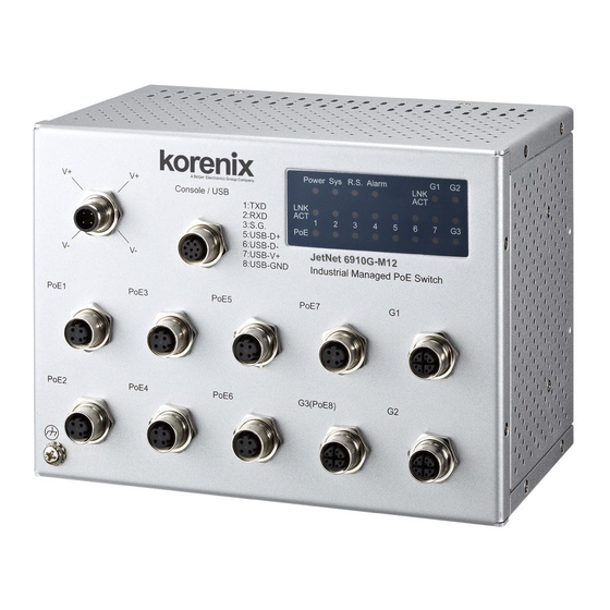
2 Hardware Installation This chapter includes hardware introduction, installation and configuration information. Following topics are covered in this chapter: 2.1 Hardware Introduction 2.2 Wiring Power Inputs 2.3 Wiring Earth Ground 2.4 Wiring Fast Ethernet Ports 2.5 Wiring RS-232 console cable 2.6 Bypass Fault Device in Daisy Chain or Ring 2.7 M12 USB Auto-Configuration 2.8 Wall Mounting Installation... - Page 10 Dimension (HxWxD) mm 145.2(H) x 198 (W) x 120 (D) without Bracket 145.2(H) x 230.6 (W) x 121.7 (D) with Bracket Panel Layout The front panel includes M12-based USB/Console Port, Fast/Gigabit Ethernet Port, Power and System/Port LEDs.
-
Page 11: Wiring Power Inputs
Figure of JetNet 6910G-M12, 7+3G Managed Ethernet Switch Wiring Power Inputs For DC power inputs. Insert positive and negative wires into V+ and V- contacts respectively of the M12 connector (Plug-side). Tighten the nuts to prevent the loosening of the M12 connectors. - Page 12 Gigabit Ethernet ports(#8~#10, M12 X-code), and the PoE/ PSE function present at M12 D-Code Fast Ethernet port (#1~7) and M12 X-code Gigabit Ethernet port (#8). The connectivity information of M12 and RJ-45 shown in below: Fast Ethernet/ PoE ports, M12 D-code connector: For Fast Ethernet M12 D-code to M12 D-code connection, you can use either version below: For Fast Ethernet M12-code to RJ45 connection, the pin assignment of the patch cable is...
- Page 13 Gigabit Ethernet ports, M12 X-code For Gigabit Ethernet M12 X-code to M12 X-code connections, the pin assignment of the patch cable is shown below: For Gigabit Ethernet M12 X-code to RJ45 connection, the pin assignment of the patch cable is shown below: Connect one side of an Ethernet cable into any switch port and connect the other side to your attached device.
-
Page 14: Wiring Rs-232 Console Cable
Wiring RS-232 Console Cable JetNet 6910G-M12 attached one RS-232 DB-9 to M12-A cable in the unit box. Connect the DB-9 connector to the COM port of your PC, connect M12-A to Switch’s USB/Console port, open Terminal tool and set up serial settings to 9600, N,8,1. (Baud Rate: 9600 / Parity: None / Data Bit: 8 / Stop Bit: 1) Then you can access CLI interface by console able. -
Page 15: Wall Mounting Installation
USB and save the configuration to the Ethernet Switch memory and apply the new configuration into system when boot up. (b)Name: AutoLoadConfiguration.conf Auto Load Configuration and apply the configuration to Ethernet Switch without saving to memory. (c)If both files exist in the USB, then the AutoLoadSaveConfiguration.conf has the higher priority and will perform Auto load and saving actions. -
Page 16: Safety Warning
Safety Warning The Equipment intended for installation in a Restricted Access Location. This Ethernet Switch is intended for Railway/Train on-board application. Thus, all of the installation should be performed by professional Engineer who is familiar Train communication and electrical power system. -
Page 17: Preparation For Management
3.3 Preparation for Telnet console Preparation for Serial Console In JetNet 6910G-M12 package, Korenix attached one RS-232 M12 to DB-9 console cable. Please attach RS-232 DB-9 connector to your PC COM port, connect the other end to the Console port of the JetNet 6910G-M12. Note: If you lost the cable, please contact with your sales or follow the pin assignment to buy a new one. -
Page 18: Preparation For Web Interface
Web Interface Korenix web management GUI page is developed by JAVA or *CGI. It allows to use a standard web-browser such as Microsoft Internet Explorer, or Mozilla, Chrome to configure and interrogate the switch from anywhere on the network in the same domain. -
Page 19: Preparation For Telnet Console
3.3.1 Telnet Korenix JetNet 6910G-M12 supports Telnet console. You can connect to the switch by Telnet and the command lines are the same as what you see by RS232 console port. Below are the steps to open Telnet connection to the switch. - Page 20 Download PuTTY: http://www.chiark.greenend.org.uk/~sgtatham/putty/download.html The copyright of PuTTY Open SSH Client/PuTTY In the Session configuration, enter the Host Name (IP Address of your JetNet 6910G- M12) and Port number (default = 22). Choose the “SSH” protocol. Then click on “Open” to start the SSH session console. 2.
- Page 21 After few seconds, the SSH connection to JetNet 6910G-M12 is opened. You can see the login screen as the below figure . (the following is refer to JetNet 5010G) 4. Type the Login Name and its Password. The default Login Name and Password are admin / admin.
-
Page 22: Feature Configuration
4 Feature Configuration This chapter explains how to configure the Managed Switch’s software features. There are four ways to access the switch: Serial console, Telnet, Web browser and SNMP. The Managed Switch Series provides both in-band and out-band configuration methods. The connectivity of both in-band and out-band is described in previous chapter. -
Page 23: Command Line Interface Introduction
Command Line Interface Introduction The Command Line Interface (CLI) is the user interface to the switch’s embedded software system. An network administrator can view the system information, show the status, configure the switch and receive a response back from the system by input a CLI command. - Page 24 Global Configuration Mode: Press configure terminal in privileged EXEC mode. Adminstrator can then enter global configuration mode. In global configuration mode, administrator can configure all the features that the system provides. Type interface IFNAME/VLAN to enter interface configuration mode, exit to leave. ? to see the command list.
- Page 25 Available command lists of the (port) Interface configuration mode. Switch(config)# interface fa1 Switch(config-if)# acceptable Configure 802.1Q acceptable frame types of a port. auto-negotiation Enable auto-negotiation state of a given port description Interface specific description dot1x IEEE 802.1x access security control duplex Specify duplex mode of operation for a port End current mode and change to enable mode...
- Page 26 Summary of the 5 command modes. Command Main Function Enter and Exit Method Prompt Mode User EXEC This is the first level of access. Enter: Login successfully Switch> User can ping, telnet remote Exit: exit to logout. device, and show some basic Next mode: Type enable to information enter privileged EXEC mode.
- Page 27 Here are some useful commands for you to see these available commands. Save your time in typing and avoid typing error ? To see all the available commands in this mode. It helps to see the possible, available commands for use. Switch(config)# interface (?) IFNAME Interface's name vlan...
-
Page 28: Basic Setting
Basic Setting The Basic Setting group provides the way to configure switch information, IP address, User name/ Password of the system. It also allows you to do firmware upgrade, backup and restore configuration, reload factory default, and reboot the system. Following commands are included in this group: 4.2.1 Switch Setting 4.2.2 Admin Password... - Page 29 System OID: The SNMP object ID of the switch. Administrator can follow the path to find its private MIB in MIB browser. (Note: When administrator attempt to view private MIB, yit’s required to compile private MIB files into the MIB browser first.) System Description: JetNet6910G-M12 Industrial Managed Ethernet Switch is the name of this product.
- Page 30 RADIUS Server IP: The IP address of the RADIUS server. Shared Key: The password for communication between the switch and the RADIUS Server. Server Port: UDP port of the RADIUS server. Apply: button to apply the RADIUS Server and Secondary RADIUS Server configurations.
- Page 31 identical default IPv6 address. (ex: 00:12:77:FF:88:88 -> fe80::212:77ff:feff:8888) IPv6 Address: a new IPv6 address can be assigned in this field. Prefix: the size of the subnet or network, and is equivalent to the subnet mask, but expressed in a different way. The default length of the subnet mask is 64bits, and written in decimal value - 64.
- Page 32 re-compute the offset between its clock and the master's clock. *Note: Please enable one synchronization protocol (PTP/NTP) only. JetNet 6910G-M12 also provides Daylight Saving function. System Time: The current time of the system. The time can be synchronized from PC, NTP Server, IEEE 1588 server or the device startup duration.
- Page 33 24 (GMT-01:00) Cape Verde Is. 25 (GMT) Casablanca, Monrovia 26 (GMT) Greenwich Mean Time: Dublin, Edinburgh, Lisbon, London 27 (GMT+01:00) Amsterdam, Berlin, Bern, Rome, Stockholm, Vienna 28 (GMT+01:00) Belgrade, Bratislava, Budapest, Ljubljana, Prague 29 (GMT+01:00) Brussels, Copenhagen, Madrid, Paris 30 (GMT+01:00) Sarajevo, Skopje, Sofija, Vilnius, Warsaw, Zagreb 31 (GMT+01:00) West Central Africa 32 (GMT+02:00) Athens, Istanbul, Minsk 33 (GMT+02:00) Bucharest...
- Page 34 Configuration can be accomplished by clicking on Apply button NTP client: Select the Time Setting Source to NTP client can let device enable the NTP client service. NTP client will be automatically enabled if Time source is changed to NTP Client.
- Page 35 Excluded Address: Administrator can type a specific address into the IP Address field for the DHCP server reserved IP address. The IP address that is listed in the Excluded Address List Table will not be assigned to the network device. Add or remove an IP address from the Excluded Address List by clicking Add or Remove.
- Page 36 Option 82 IP Address Configuration: The DHCP can assign IP address according to DHCP Option82 which sent from DHCP Relay Agent. DHCP Leased Entries: JetNet 6190G- M12 provides assigned IP address list for user reference. It will show the MAC and IP address assigned by 6910G- M12.
- Page 37 4.2.6 Backup and Restore With Backup command, an administrator can save current configuration file saved in the switch’s flash to admin PC or TFTP server. This will allow administrator to go by Restore command later to restore the configuration file back to the switch. Before restoring the configuration file, it is required to place the backup configuration file in the PC or TFTP server.
- Page 38 openned by text editor to read the file. Administrator can also modify the file, add/remove the configuration settings, and then restore back to the switch. Startup Configuration File: After the running-config is saved to flash, the new settings will be kept and work after power cycle. Administrator can use show startup-config to view it in CLI.
- Page 39 4.2.7 Firmware Upgrade In this section, an administrator can update the latest firmware for the switch. Korenix provides the latest firmware at Korenix Web site. The new firmware may include new features, bug fixes or other software changes. The release notes is along with the update as well.
- Page 40 Error Message due to the file error or not a firmware for the switch. Before upgrading firmware, please assure that the firmware specific is for JetNet 6910G- M12. The switch provide protection when an incorrect firmware file is being upgraded, the system crash would not be expected by an incorrect firmware being updated.
- Page 41 (System Name, Software Information : Location, Contact; Loader Version : 1.0.0.0 Firmware Version : 1.0_b1-20160201-16:19:04 System Firmware Copyright 2006-2015 Korenix Technology Co., Ltd. and Loader version, MAC address, LED Switc # show hardware led led information status) mac mac address...
- Page 42 admin/admin). . Display Switch# show administrator Administrator account information name: admin password: 8888 IP Configuration IP Address/Mask Switch(config)# int vlan 1 (192.168.10.8, Switch(config-if)# ip 255.255.255.0 Interface Internet Protocol config commands ipv6 Interface Internet Protocol config commands Switch(config-if)# ip address 192.168.10.13/24 (DHCP Client) Switch(config-if)# ip dhcp client Switch(config-if)# ip dhcp client renew...
- Page 43 Switch(config)# ipv6 route 0::0/0 IPv6 Gateway 2001:0db8:85a3::8a2e:0370:FFFE Switch(config)#no ipv6 route 0::0/0 Remove IPv6 2001:0db8:85a3::8a2e:0370:FFFE Gateway Switch# show running-config Display ……… interface vlan1 ip address 192.168.10.6/24 ipv6 address 2001:db8:85a3::8a2e:370:7334/64 no shutdown ip route 0.0.0.0/0 192.168.10.254 ipv6 route ::/0 2001:db8:85a3::8a2e:370:fffe Time Setting NTP Server Switch(config)# ntp peer disable...
- Page 44 Switch(config-dhcp)# ip dhcp excluded-address DHCP Server – A.B.C.D IP address Excluded Address Switch(config-dhcp)# ip dhcp excluded-address 192.168.10.123 Switch(config-dhcp)# ip dhcp static port DHCP Server – PORT IP Address Static Port-IP binding Switch(config-dhcp)# ip dhcp static port 3 111.111.111.111 Switch(config-dhcp)# ip dhcp static 0012.7700.0001 DHCP Server –...
- Page 45 Configuration file Note 1: To backup the latest startup configuration file, you should save current settings to flash first. You can refer to 4.12 to see how to save settings to the flash. Note 2: 192.168.10.33 is the TFTP server’s IP and default.conf is the name of the configuration file.
-
Page 46: Port Configuration
Port Configuration This chapter delivers guidance on the configuration setting of switch ports, including port state enable/disable, auto-negotiation, speed, duplex, flow control, rate limit control and port aggregation settings. The port status and aggregation information can be also achieved. Following commands are mentioned in this chapter : 4.3.2 Port Control 4.3.3 Port Status 4.3.4 Rate Control... - Page 47 In State column, the selected port can be enabled or disabled. Once the port disabled, the port linkage is down and stop to forward any traffic. The default setting is Enable which all the ports are taken in functional upon transmission and receiving. In Speed/Duplex column, the port speed and duplex mode can be configured, including the following selections: Fast Ethernet Port 1~7 (fa1~fa7): AutoNegotiation, 10Mb Full Duplex(10 Full), 10Mb Half...
- Page 48 State: Enable -> State is enabled. Disable -> The port is disable/shutdown. Speed/Duplex: Current working status of the port. Flow Control: The state of the flow control. 4.3.4 Rate Control Rate limiting is a form of flow control used to enforce a strict bandwidth limit at a port. It can be programmed separately the transmit (Egress Rule) and receive (Ingress Rule) rate limits at each port, and even apply the limit to certain packet types as described below.
- Page 49 Aggregation Setting Trunk Size: The switch can support up to 8 trunk groups. Each trunk group can support up to 8 member ports. Since the member ports should use same speed/duplex, the maximum trunk size is decided by the port volume in total. Group ID: Group ID is the ID for the port trunking group.
- Page 50 Group ID: Display Trunk 1 to Trunk 5 set up in Aggregation Setting. Type: Static or LACP set up in Aggregation Setting. Aggregated: When LACP links well, you can see the member ports in “Aggregated “column. Individual: When LACP is enabled, member ports of LACP group which are not connected to correct LACP member ports will be displayed in the Individual column.
- Page 51 Flow Control : off Default Port VLAN ID: 1 Acceptable Frame Type : All Auto Negotiation : Enable Loopback Mode : None STP Status: Forwarding Default CoS Value for untagged packets is 0. Medium mode is Copper. Note: Administrative Status -> Port state of the port. Operating status ->...
- Page 52 Storm-control for Port 3 Broadcast packets: Disabled Destination Lookup Failure packets: Disabled Multicast packets: Disabled Storm-control for Port 4 Broadcast packets: Disabled Destination Lookup Failure packets: Disabled Multicast packets: Disabled ………. Port Trunking LACP Switch(config)# lacp group 1 fa8-10 Group 1 based on LACP(802.3ad) is enabled! Note: The interface list is fa1,fa3-5, fa8-10 Note: different speed port can’t be aggregated together.
- Page 53 ----- ----------- -------- -------- ------- 0x45 0x45 0x45 LACP group 2 is inactive LACP group 3 is inactive LACP group 4 is inactive Switch# show trunk group 1 Display - Trunk FLAGS: I -> Individual P -> In channel D -> Port Down Trunk Group TGID Protocol Load-Balance Ports -----+---------+------------+-------------------------------------...
-
Page 54: Power Over Ethernet
Power Over Ethernet Power over Ethernet is one of the key features of JetNet 6910G-M12. It is fully IEEE802.3af-2003 compliant, and support IEEE802.3at, including 1-event with IEEE 802.1AB LLDP classification for PoE MDI signaling. The JetNet 6910G-M12 adopts 8-Port PoE injectors from port 1 to port 8, each port with the ability is able to deliver 30W power per IEEE 802.3at 2-event plus LLDP function. - Page 55 DC, by setting variable resistor equipped in the switching power supply. For the JetNet 6910G-M12 series, the internal DC/DC output voltage is required DC 54V at minimum; so the a lower value in “power budget” may not impact when a high DC 110V input is presented.
- Page 56 4.4.2 PoE Scheduling The PoE Scheduling control is a powerful function to help you save power and money. Administrator can configure PoE Scheduling with selecting a target port manually to enable this function. The Power over Ethernet schedule supports hourly and weekly base PoE schedule configuration.
- Page 57 4.4.4 Command Line for PoE Control Syntax show poe system Parameters Command Mode Enable mode Description Display the status of the PoE system. Examples Switch> enable Switch# show poe system PoE System PoE Admin : Enable PoE Hardward : Normal Ouput power : 0.0 Watts Power Budget : Budget: 100 Watts...
- Page 58 Operation Status : Off Detection Status : Valid Classification : N/A Priority : Highest Output Power : 0.0 Watts, Voltage : 0.0 V, Current : 0 mA Power Budget : Budget : 32.0 Watts, effective 0 Watts Warning water level : N/A Utilization : 0 % Event : Normal Syntax...
- Page 59 Examples EX 1: Set 802.3af powring mode Switch(config)# poe powering-mode 802.3af EX 2: Set forced powering mode Switch(config)# poe powering-mode forced Syntax poe powering-mode 802.3at 2-event/lldp Parameters 2-event: deliver power if and only if the attached PD comply with IEEE 802.3at physical layer classification lldp: deliver power if and only if the attached PD comply with IEEE 802.3at data link layer classification Command Mode...
- Page 60 forced powering mode. The max budget of 802.3af powering mode is 15.4. The max budget of 802.3at powering mode is 32. The max budget of force powering mode is 32. Examples Set the max value of power consumption to 12 W with manual mode.
-
Page 61: Network Redundancy
A single Korenix switch can aggregate multiple Rings within itself. All the ports can be configured as the ring port of a ring, each ring has its own Ring ID and the Ring ID will be added to the watchdog packet to monitor the ring status. - Page 62 Following commands are included in this group: 4.5.1 STP Configuration 4.5.2 STP Port Configuration 4.5.3 STP Information 4.5.4 MSTP Configuration 4.5.5 MSTP Port Configuration 4.5.6 MSTP information 4.5.7 Multiple Super Ring 4.5.8 Multiple Super Ring Information 4.5.9 Loop Protection 4.5.10 Command Lines for Network Redundancy The STP Configuration, STP Port Configuration and STP Information pages are available while select the STP and RSTP mode.
- Page 63 of message loops in switched networks. A spanning tree uses a spanning tree algorithm (STA) to automatically sense whether a switch has more than one way to communicate with a node. It will then select the best path (primary), and block the other path(s). It will also keep track of the blocked path(s) in case the primary path fails.
- Page 64 amount of time the root has waited during sending hello messages. Forward Delay Time (4-30): Enter a value between 4 and 30 seconds. This value is the time that a port waits before changing from Spanning Tree Protocol learning and listening states to forwarding state.
- Page 65 Once you finish your configuration, click on Apply to save your settings. 4.5.3 RSTP Info This page allows you to see the information of the root switch and port status. Root Information: You can see root Bridge ID, Root Priority, Root Port, Root Path Cost and the Max Age, Hello Time and Forward Delay of BPDU sent from the root switch.
- Page 66 One VLAN can be mapped to a Multiple Spanning Tree Instance (MSTI). For example, the maximum Instance of the Managed Switch supports is usually 16, range from 0-15. The MSTP builds a separate Multiple Spanning Tree (MST) for each instance to maintain connectivity among each of the assigned VLAN groups.
- Page 67 To configure the MSTP setting, the STP Mode of the STP Configuration page should be changed to MSTP mode first. After enabled MSTP mode, then you can go to the MSTP Configuration pages. MSTP Region Configuration This page allows configure the Region Name and its Revision, mapping the VLAN to Instance and check current MST Instance configuration.
- Page 68 4.5.5 MSTP Port Configuration This page allows configure the Port settings. Choose the Instance ID you want to configure. The MSTP enabled and linked up ports within the instance will be listed in this table. Note that the ports not belonged to the Instance, or the ports not MSTP activated will not display.
- Page 69 Click on “Reload“ to reload the MSTP information display. 4.5.7 Multiple Super Ring (MSR) The most common industrial network redundancy is to form a ring or loop. Typically, the managed switches are connected in series and the last switch is connected back to the first one.
- Page 70 Ring Configuration ID: Once a Ring is created, it appears and cannot be changed. Name: This field will show the name of the Ring. If it is not filled in when creating, it will be automatically named by the rule “RingID”. Version: The version of Ring can be changed here.
- Page 71 and Member. Border is the node which connects to foreign network. Member is the node except the Border node in the Super Chain. Edge Port: Edge Port is one of ring ports of Border node. It is used to connect to foreign network.
- Page 72 4.5.10 Command Lines Feature Command Line Global Enable Switch(config)# spanning-tree enable Disable Switch (config)# spanning-tree disable Mode (Choose the Switch(config)# spanning-tree mode Spanning Tree rst the rapid spanning-tree protocol (802.1w) mode) stp the spanning-tree prtotcol (802.1d) mst the multiple spanning-tree protocol (802.1s) Bridge Priority Switch(config)# spanning-tree priority <0-61440>...
- Page 73 Switch(config-mst)# na69orenixnix Region Revision: Switch(config-mst)# revision <0-65535> the value of revision Switch(config-mst)# revision 65535 Mapping Instance Switch(config-mst)# instance to VLAN (Ex: <1-15> target instance number Mapping VLAN 2 Switch(config-mst)# instance 1 vlan to Instance 1) VLANMAP target vlan number(ex.10) or range(ex.1-10) Switch(config-mst)# instance 1 vlan 2 Display Current Switch(config-mst)# show current...
- Page 74 -------- -------------------------------------- 1,4-4094 (-> The instance is not applied after Abort settings-- Config HMAC-MD5 Digest: 0xB41829F9030A054FB74EF7A8587FF58D ------------------------------------------------ RSTP The mode should be rst, the timings can be configured in global settings listed in above. Global Information Active Information Switch# show spanning-tree active Spanning-Tree : Enabled Protocol : MSTP Root Address :...
- Page 75 Message-Age Expired count MSTP Information– MSTP Switch# show spanning-tree mst configuration Configuraiton– Current MST configuration (MSTP is Running) Name 71orenixnix] Revision 65535 Instance Vlans Mapped -------- -------------------------------------- 1,4-4094 Config HMAC-MD5 Digest: 0xB41829F9030A054FB74EF7A8587FF58D ------------------------------------------------ Display all MST Switch# show spanning-tree mst Information ###### MST00 vlans mapped: 1,4-4094...
- Page 76 Internal(MSTP) fa2 Designated Forwarding 200000 128.2 Internal(MSTP) MSTP Port Switch# show spanning-tree mst interface fa1 Information Interface fastethernet1 of MST00 is Designated Forwarding Edge Port : Edge (Edge) BPDU Filter : Disabled Link Type : Auto (Point-to-point) BPDU Guard : Disabled Boundary : Internal(MSTP) BPDUs : sent 6352, received 0 Instance...
- Page 77 Switch(config-multiple-super-ring)# rapid-dual-homing port IFLIST Interface name, ex: fastethernet1 or gi8 auto-detect up link auto detection IFNAME Interface name, ex: fastethernet1 or gi8 Switch(config-multiple-super-ring)# rapid-dual-homing port fa3,fa5-6 set Rapid Dual Homing port success. Switch(config-multiple-super-ring)#rapid-dual-homing extension <0-7> extension ID 0-7 (default is 0) default Note: auto-detect is recommended for dual Homing..
- Page 78 Timers WTR Timer : period is 1 minutes, timer is not running, remains 0 ms Guard Timer : period is 100 ms, timer is not running, remains 0 ms Statistics R-APS(SF) : sent 0, received 0 R-APS(NR,RB) : sent 0, received 0 R-APS(NR) : sent 0, received 0 Node State Transition count 0...
-
Page 79: Vlan
4.6 VLAN A Virtual LAN (VLAN) is a “logical” grouping of nodes for the purpose of limiting a broadcast domain to specific members of a group without physically grouping the members together. It means that VLAN can isolate network traffic so that only members of VLAN could receive traffic from the same VLAN members. - Page 80 Ingress/Egress parameters and view VLAN table. Following commands are included in this group: 4.6.1 VLAN Port Configuration 4.6.2 VLAN Configuration 4.6.3 GVRP Configuration 4.6.4 VLAN Table 4.6.5 CLI Commands of the VLAN 4.6.1 VLAN Port Configuration VLAN Port Configuration allows you to set up VLAN port parameters to specific port. These parameters include PVID, Accept Frame Type and Ingress Filtering.
- Page 81 Tunnel Mode: This is the new command for QinQ. The command includes None, 802.1Q Tunnel and 802.1Q Tunnel Uplink. The figure shows the relationship between 802.1Q Tunnel and 802.1Q Tunnel Uplink. Following is the modes you can select. None: Remian VLAN setting, no QinQ. 802.1Q Tunnel: The QinQ command applied to the ports which connect to the C-VLAN.
- Page 82 4.6.2 VLAN Configuration In this page, administrator can assign Management VLAN, create the static VLAN, and assign the Egress rule for the member ports of the VLAN. Figure 4.6.2.1 Web UI of the VLAN Configuration. Management VLAN ID: The switch supports management VLAN. The management VLAN ID is the VLAN ID of the CPU interface of the control plane in the switch so that only member ports of the management VLAN can ping and access the switch.
- Page 83 Untagged or Tagged here. Figure 4.6.2.3 Static VLAN Configuration table. The new VLAN 3 is created. VLAN name is “ test”. Egress rules of the ports are not configured now. Figure 4.6.2.4 Configure Egress rule of the ports. -- : Not available U: Untag: Indicates that egress/outgoing frames are not VLAN tagged.
- Page 84 Leave Timer: Control the time to release the GVRP reservation after received the GVRP Leave BPDU. An instance of the timer is required for each state machine that is in the LV state Leave All Timer: Controls the period to initiate the garbage collection of registered VLAN. The timer is required on a per-Port, per-GARP Participant basis 4.6.4 VLAN Table...
- Page 85 any kind of frame type is accepted! Switch(config-if)# acceptable frame type vlantaggedonly only vlan-tag frame is accepted! Egress rule – Untagged Switch(config-if)# switchport access vlan 2 (for VLAN 2) switchport access vlan add success Egress rule – Tagged Switch(config-if)# switchport trunk allowed vlan add 2 (for VLAN 2) Display –...
- Page 86 ……… ……… interface fastethernet5 switchport access vlan add 1-2,10 switchport dot1q-tunnel mode access interface fastethernet6 switchport access vlan add 1-2 switchport trunk allowed vlan add 10 switchport dot1q-tunnel mode uplink VLAN Configuration Create VLAN (2) Switch(config)# vlan 2 vlan 2 success Switch(config)# interface vlan 2 Switch(config-if)# Note: In CLI configuration, you should create a VLAN...
- Page 87 Display – VLAN Switch# show interface vlan1 Interface vlan1 interface information Description : N/A Administrative Status : Enable Operating Status : Up DHCP Client : Disable Primary IP Address : 192.168.10.1/24 IPv6 Address : fe80::212:77ff:feff:2222/64 GVRP configuration GVRP enable/disable Switch(config)# gvrp mode disable Disable GVRP feature globally on the switch enable Enable GVRP feature globally on the switch...
-
Page 88: Private Vlan
4.7 Private VLAN The private VLAN helps to resolve the primary VLAN ID shortage, client ports’ isolation and network security issues. The Private VLAN provides primary and secondary VLAN within a single switch. Primary VLAN: The uplink port is usually the primary VLAN. A primary VLAN contains promiscuous ports that can communicate with lower Secondary VLANs. - Page 89 Community: The VLAN is the Community VLAN. The member ports of the VLAN can communicate with each other. 4.7.2 PVLAN Port Configuration PVLAN Port Configuration page allows configure Port Configuration and Private VLAN Association. Private VLAN Association Secondary VLAN: After the Isolated and Community VLAN Type is assigned in Private VLAN Configuration page, the VLANs are belonged to the Secondary VLAN and displayed here.
- Page 90 For example: 1. VLAN Create: VLAN 2-5 are created in VLAN Configuration page. 2. Private VLAN Type: VLAN 2-5 has its Private VLAN Type configured in Private VLAN Configuration page. VLAN 2 is belonged to Primary VLAN. VLAN 3-5 are belonged to secondary VLAN (Isolated or Community). 3.
- Page 91 4.7.3 Private VLAN Information This page allows you to see the Private VLAN information. 4.7.4 CLI Command of the PVLAN Command Lines of the Private VLAN configuration Feature Command Line Private VLAN Configuration Create VLAN Switch(config)# vlan 2 vlan 2 success Switch(config-vlan)# End current mode and change to enable mode exit...
- Page 92 Switch(config-vlan)# private-vlan primary Isolated Type Switch(config-vlan)# no private-vlan primary Switch(config-vlan)# private-vlan isolated Community Type Switch(config-vlan)# no private-vlan isolated Switch(config-vlan)# private-vlan community Switch(config-vlan)# no private-vlan community Private VLAN Port Configuraiton Go to the port Switch(config)# interface (port_number, ex: gi9) configuraiton Switch(config-if)# switchport private-vlan host-association Set the private VLAN host association mapping map primary VLAN to secondary VLAN...
- Page 93 primary gi10 isolated community community fa7,gi9 primary Host List Switch# show vlan private-vlan port-list Ports Mode Vlan ----- ----------- ---- normal normal normal normal normal normal host host host promiscuous 2 Running Config Switch# show run Information Building configuration... Current configuration: hostname Switch vlan learning independent vlan 1...
-
Page 94: Traffic Prioritization
switchport private-vlan host-association 2 3 interface Gigabit Ethernetbitethernet10 switchport access vlan add 2,5 switchport trunk native vlan 2 switchport mode private-vlan promiscuous switchport private-vlan mapping 2 add 3-5 ……… …….. 4.8 Traffic Prioritization Quality of Service (QoS) provides traffic prioritization mechanism which allows users to deliver better service to certain flows. - Page 95 scheme allows users to assign new weight ratio for each class. The 10 is the highest ratio. The ratio of each class is as below: / W0 + W1 + W2 + W3 + W4 + W5 + W6 + W7 (Total volume of Queue 0-7) 4.8.2 Port-based Queue Mapping Choose the Queue value of each port, the port then has its default priority.
- Page 96 4.8.5 CLI Commands of the Traffic Prioritization Command Lines of the Traffic Prioritization configuration Feature Command Line QoS Setting Queue Scheduling – Switch(config)# qos queue-sched Strict Priority Strict Priority wrr Weighted Round Robin Switch(config)# qos queue-sched sp The queue scheduling scheme is setting to Strict Priority. Queue Scheduli–g - Switch(config)# qos queue-sched wrr <1-10>...
- Page 97 ……….. CoS-Queue Mapping Format Switch(config)# qos cos-map PRIORITY Assign an priority (7 highest) Switch(config)# qos cos-map 1 QUEUE Assign an queue (0-7) Note: Format: qos cos-map priority_value queue_value Map CoS 0 to Queue 1 Switch(config)# qos cos-map 0 1 The CoS to queue mapping is set ok. Map CoS 1 to Queue 0 Switch(config)# qos cos-map 1 0 The CoS to queue mapping is set ok.
- Page 98 -----+---------------------- 0 | 1 0 0 0 0 0 0 0 1 1 1 | 1 1 1 1 1 1 2 2 2 2 2 | 2 2 2 2 3 3 3 3 3 3 3 | 3 3 4 4 4 4 4 4 4 4 4 | 5 5 5 5 5 5 5 5 6 6 5 | 6 6 6 6 6 6 7 7 7 7 6 | 7 7 7 7...
-
Page 99: Multicast Filtering
4.9 Multicast Filtering For multicast filtering, JetNet 6910G-M12 uses IGMP Snooping technology. IGMP (Internet Group Management Protocol) is an Internet Protocol that provides a way for internet device to report its multicast group membership to adjacent routers. Multicasting allows one computer on the internet to send data to a multitude of other computers that have identified themselves as being interested in receiving the originating computers data. - Page 100 IGMP Snooping, administrator can select Enable or Disable here. After enabling IGMP Snooping, then enable IGMP Snooping for specific VLAN. It’s possible to enable IGMP Snooping for some VLANs so that these specified VLANs can support IGMP Snooping and others don’t. To assign IGMP Snooping to VLAN, please select VLAN ID to enable/disable IGMP Snooping function, or select the...
- Page 101 IGMP querier, a switch with the lowest IP address becomes the IGMP querier. In IGMP Query selection, administrator can select V1, V2 or Disable. V1 means IGMP V1 General Query and V2 means IGMP V2 General Query.. The query will be forwarded to all multicast groups in the VLAN.
- Page 102 IGMP snooping is enabled on vlan 2 Disable IGMP Snoopi– Switch(config)# no ip igmp snoopin g - Global IGMP snooping is disabled globally ok. Disable IGMP Snoopi– Switch(config)# no ip igmp snooping vlan 3 g - VLAN IGMP snooping is disabled on VLAN 3. Display –...
- Page 103 Unknown Multicast Send to Query Ports – Switch(config)# ip igmp snooping source-only-learning vlan VLANLIST allowed VLAN list all VLAN Switch(config)# ip igmp snooping source-only-learning vlan 1 IGMP Snooping Source-Only-Learning is enabled on VLAN 1 Discard (Force filtering) Switch(config)# mac-address-table multicast filtering vlan VLANLIST allowed VLAN list all VLAN Switch(config)# mac-address-table multicast filtering vlan 2...
-
Page 104: Snmp
4.10 SNMP Simple Network Management Protocol (SNMP) is a protocol used for exchanging management information between network devices. SNMP is a member of the TCP/IP protocol suite. The Managed Switch series support SNMP v1 and v2c and V3. (Web Managed Switch doesn’t support SNMP feature.) An SNMP managed network consists of two main components: agents and a manager. - Page 105 This page allows users to Enable SNMP Trap, configure the SNMP Trap server IP, Community name, and trap version V1 or V2c. After configuration, you can see the change of the SNMP pre-defined standard traps and Korenix pre-defined traps. The pre- defined traps can be found in Korenix private MIB.
- Page 106 4.10.4 CLI Commands of the SNMP Command Lines of the SNMP configuration Feature Command Line SNMP Community Read Only Community Switch(config)# snmp-server community public ro community string add ok Read Write Community Switch(config)# snmp-server community private rw community string add ok SNMP Trap Enable Trap Switch(config)# snmp-server enable trap...
- Page 107 SNMP trap: Enabled SNMP trap community: public Switch# show running-config ..snmp-server community public ro snmp-server community private rw snmp-server enable trap snmp-server host 192.168.10.33 version 2 admin snmp-server host 192.168.10.33 version 1 admin ……..
-
Page 108: Security
4.11 Security JetNet 6910G-M12 provides several security features to secure the connection. The security design features Port Based MAC address Security, IP security and IEEE 802.1x. Following commands are included in this group: 4.11.1 Port Security 4.11.2 IP Security 4.11.3 IEEE 802.1x 4.11.4 CLI Commands of the Security 4.11.1 Port Security Port Security feature is to stop the MAC address learning for specific... - Page 109 4.11.2 IP Security In IP Security section, it is required to have a specific IP addresses to grant authorization for management access to this JetNet via a web browser or Telnet. IP Security: Select Enable and Apply to enable IP security function. Add Security IP: specific IP addresses for security can be assigned here, and then click “Add”...
- Page 110 Secondary Radius Server IP: Secondary Radius Server could be set in case of the primary radius server down. Local Radius User: Here User can add Account/Password for local authentication. Local Radius User List: This is a list shows the account information, User also can remove selected account Here.
- Page 111 802.1x Port Configuration After the configuration of Radius Server or Local user list, administrator also needs to configure the authentication mode, authentication behavior, applied VLAN for each port and permitted communication. The following information will explain the port configuration. Once these settings are configured, click on Apply to take effective for these changes. Port control: Force Authorized indicates this specified port is authorized;...
- Page 112 Host Mode: if there are more than one device connected to this port, set the Host Mode to single means only the first PC authenticate success can access this port. If this port is set to multi, all the device can access this port once any one of them pass the authentication. Control Direction: determined devices can end data out only or both send and receive.
- Page 113 4.11.4 CLI Commands of the Security Command Lines of the Security configuration Feature Command Line Port Security Add MAC access list Switch(config)# mac access-list extended NAME access-list name Switch(config)# mac access-list extended server1 Switch(config-ext-macl)# permit Specify packets to forward deny Specify packets to reject End current mode and change to enable mode exit...
- Page 114 Switch(config-ext-macl)#permit host 0012.7711.2233 MACADDR Destination MAC address xxxx.xxxx.xxxx any destination MAC address host A single destination host Switch(config-ext-macl)#permit host 0012.7711.2233 host MACADDR Destination MAC address xxxx.xxxx.xxxx Switch(config-ext-macl)#permit host 0012.7711.2233 host 0011.7711.2234 [IFNAME] Egress interface name Switch(config-ext-macl)#permit host 0012.7711.2233 host 0011.7711.2234 gi25 Note: MAC Rule: Permit/Deny wildcard Source_MAC wildcard Dest_MAC Egress_Interface Example 1: Edit IP...
- Page 115 Enable new MAC addresses learning and aging activities! Display Switch# show mac-address-table static Destination Address Address Type Vlan Destination Port ------------------- --------------- ------- ------------------------ 0012.7701.0101 Static 802.1x (shot of dot1x) enable Switch(config)# dot1x system-auth-control Switch(config)# diable Switch(config)# no dot1x system-auth-control Switch(config)# authentic-method Switch(config)# dot1x authentic-method...
- Page 116 authentic-method Dot1x authentic-method interface Interface name radius Remote Access Dial-In User Service statistics Interface name username User Name in local radius database Switch# show dot1x <cr> = Switch# show dot1x all You can check all dot1x information for all interfaces. Click Ctrl + C to exit the display Switch# show dot1x interface fa1 Supplicant MAC ADDR <NONE>...
-
Page 117: Warning
4.12 Warning JetNet 6910G-M12 offers several types of Warning features to remotely monitor the status of end devices or the change of your network. The features include System Log and SMTP E-mail Alert. Following commands are included in this group: 4.12.1 Event Selection 4.12.2 Syslog Configuration 4.12.3 SMTP Configuration... - Page 118 short circuit. Dry Output Relay continuous perform On/Off behavior with different duration. Warning Event is sent when….. Port Event Link-Up The port is connected to another device Link-Down The port is disconnected (e.g. the cable is pulled out, or the opposing devices turns down) Once you finish configuring the settings, click on Apply to apply your configuration.
- Page 119 Field Description SMTP Server IP Address Enter the IP address of the email Server Authentication Click on check box to enable password User Name Enter email Account name (Max.40 characters) Password Enter the password of the email account Confirm Password Re-type the password of the email account You can set up to 4 email addresses to receive email alarm from Managed Switch Rcpt E-mail Address 1...
- Page 120 4.12.4 CLI Commands Command Lines of the Warning configuration Feature Command Line Relay Output Relay Output Switch(config)# relay 1 dry output ping ping failure port port link failure ring ring failure Dry Output Switch(config)# relay 1 dry <0-65535> turn on period in second Switch(config)# relay 1 dry 5 <0-65535>...
- Page 121 Switch(config)# smtp-server server 192.168.10.100 ACCOUNT SMTP server mail account, ex: admin@korenix.com Switch(config)# smtp-server server 192.168.10.100 admin@korenix.com SMTP Email Alert set Server: 192.168.10.100, Account: admin@korenix.com ok. admin@example. Receiver mail Switch(config)# smtp-server receipt admin@example. SMTP Email Alert set receipt 1: com ok.
-
Page 122: Monitor And Diagnostic
4.13 Monitor and Diagnostic JetNet 6910G-M12 provides several types of features for you to monitor the status of the switch or diagnose the problems encountered. The features include MAC Address Table, Port Statistics, Port Mirror, Event Log and Ping. Following commands are included in this group: 4.13.1 LLDP Configuration 4.13.2 MAC Address Table 4.13.2 Port Statistics... - Page 123 4.13.2 MAC Address Table JetNet 6910G-M12 provides 8K entries in MAC Address Table. In this page, users can change the Aging time, add Static Unicast MAC Address, monitor the MAC address or sort them by different packet types and ports. Click on Apply to change the value. Aging Time (Sec) Each switch fabric has limit size to write the learnt MAC address.
- Page 124 4.13.3 Port Statistics In this page, you can view operation statistics for each port. The statistics that can be viewed include Link Type, Link State, Rx Good, Rx Bad, Rx Abort, Tx Good, Tx Bad and Collision. Rx means the received packet while Tx means the transmitted packets. Note: If you see many Bad, Abort or Collision counts increased, that may mean your network cable is not connected well, the network performance of the port is poor…etc.
- Page 125 copied to destination/analysis ports. You can choose single port or any combination of ports, you can monitor them in Rx only, Tx only or both Rx and Tx. Click on checkbox of the Rx, Tx to select the source ports. Destination Port: This is also known as Analysis Port.
- Page 126 Modbus/TCP Register Table Word Data Type Description Address System Information Vender Name = “Korenix” 0x0000 16 words Word 0 Hi byte = ‘K’ Word 0 Lo byte = ‘o’ Word 1 Hi byte = ‘r’ Word 1 Lo byte = ‘e’...
- Page 127 Word 1 Hi byte = ‘T’ Word 1 Lo byte = ‘N’ Word 2 Hi byte = ‘e’ Word 2 Lo byte = ‘t’ Word 3 Hi byte = ‘5’ Word 3 Lo byte = ‘4’ Word 4 Lo byte = ‘2’ Word 4 Hi byte = ‘8’...
- Page 128 Ex: MAC = 01-02-03-04-05-06 Word 0 Hi byte = 0x01 Word 0 Lo byte = 0x02 Word 1 Hi byte = 0x03 Word 1 Lo byte = 0x04 Word 2 Hi byte = 0x05 Word 2 Lo byte = 0x06 0x020F to 241 words Reserved address space...
- Page 129 0x0410 1 word 0x0000:Off 0x0001:On 0xFFFF: unavailable 0x0411 1 word 0x0000:Off 0x0001:On 0xFFFF: unavailable 0x0412 1 word 0x0000:Off 0x0001:On 0xFFFF: unavailable 0x0413 1 word 0x0000:Off 0x0001:On 0xFFFF: unavailable 0x0414 to 12 words Reserved address space 0x041F 0x0420 1 word 0x0000:Off 0x0001:On 0x0421 1 word...
- Page 130 0xFFFF: unavailable 0x1240 to 1 word Duplex 0x125F 0x0000: half 0x0001: full 0x0003: auto (half) 0x0004: auto (full) 0x0005: auto 0xFFFF: unavailable 0x1260 to 1 word Speed 0x127F 0x0001: 10 0x0002: 100 0x0003: 1000 0x0004: 2500 0x0005: 10000 0x0101: auto 10 0x0102: auto 100 0x0103: auto 1000 0x0104: auto 2500...
- Page 131 0x0001: enable 0xFFFF: unavailable 0x1340 to 1 word Loopback Mode 0x135F 0x0000: none 0x0001: MAC 0x0002: PHY 0xFFFF: unavailable 0x1360 to 1 word STP Status 0x137F 0x0000: disabled 0x0001: blocking 0x0002: listening 0x0003: learning 0x0004: forwarding 0x1380 to 1 word Default CoS Value for untagged packets 0x139F 0x13A0 to...
- Page 132 0x2140 to 2 words Pause 0x217F 0x2180 to 2 words Undersize 0x21BF 0x21C0 to 2 words Fragments 0x21FF 0x2200 to 2 words Oversize 0x223F 0x2240 to 2 words Jabbers 0x227F 0x2280 to 2 words Discards 0x22BF 0x22C0 to 2 words Filtered frames 0x22FF 0x2300 to...
- Page 133 0x267F 0x2680 to 2 words Collisions 0x26BF 0x26C0 to 2 words SingleCollision 0x26FF 0x2700 to 2 words MultipleCollision 0x273F 0x2740 to 2 words ExcessiveCollision 0x277F 0x2780 to 2 words LateCollision 0x27BF 0x27C0 to 2 words Filtered 0x27FF 0x2800 to 2 words FCSError 0x283F 0x2840 to...
- Page 134 Note: 350 is the new ageing timeout value. Add Static Unicast Switch(config)# mac-address-table static 0012.7701.0101 MAC address vlan 1 interface fastethernet7 mac-address-table ucast static set ok! Note: rule: mac-address-table static MAC_address VLAN VID interface interface_name Add Multicast MAC Switch(config)# mac-address-table multicast address 0100.5e01.0101 vlan 1 interface fa6-7 Adds an entry in the multicast table ok!
- Page 135 Good Octets: 330500 Unicast: 602, Broadcast: 1, Multicast: 2261 Pause: 0, Deferred: 0, Collisions: 0 SingleCollision: 0, MultipleCollision: 0 ExcessiveCollision: 0, LateCollision: 0 Filtered: 0, FCSError: 0 Number of frames received and transmitted with a length of: 64: 2388, 65to127: 142, 128to255: 11 256to511: 64, 512to1023: 10, 1024toMaxSize: 42 Port Mirroring Enable Port Mirror...
- Page 136 Modbus/TCP Number of the Switch(config)# modbus Modbus/TCP Master idle-timeout Max interval between requests master Modbus TCP Master port Listening Port Switch(config)# modbus master <1-20> Max Modbus TCP Master Modbus/TCP idle time Switch(config)# modbus idle-timeout <200-10000> Timeout vlaue: 200-10000ms Modbus/TCP port Switch(config)# modbus port number <1-65535>...
-
Page 137: Device Front Panel
4.14 Device Front Panel The command – “Device Front Panel” that allows you to check the LED status of the switch from Web browser. Please see LED and link status of the Power, PoE, R.S. and Font Ports. Below is the example of managed Switch. Different model has its own front panel display... -
Page 138: Save (Save To Flash)
4.15 Save (Save to Flash) Save Configuration allows you to save any configuration you just made to the Flash. Powering off the switch without clicking on Save Configuration will cause loss of new settings. After selecting Save Configuration, click on Save to Flash to save your new configuration. -
Page 139: Logout
4.16 Logout The switch provides 2 logout methods. The web connection will be logged out if you don’t input any command after 300 seconds. The Logout command allows you to manually logout the web connection. Click on Yes to logout, No to go back the configuration page. Command Lines: Feature Command Line... -
Page 140: Appendix
SNMP. But, since some commands can’t be found in standard MIB, Korenix provides Private MIB to meet up the need. Compile the private MIB file by your SNMP tool. Private MIB can be found in product CD or downloaded from Korenix Web site. - Page 141 RADIUS Server authentication SNMP MIB MIB II, Bridge MIB, Ethernet Like MIB, VLAN MIB, IGMP MIB, Private Management Utility Korenix View and Korenix NMS for device finding and network topology discovery Network Time Protocol NTP with daylight saving, localize time synchronize function...
- Page 142 IEEE 802.1 QinQ Double VLAN Tag with 1522 bytes frame size Traffic Prioritize 4 physical queues, supports weighted fair queuing (WRR) and strict priority scheme, follows COS tag ID, IPv4 ToS/DiffServ information to prioritize the traffic Multicasting IGMP Snooping v1/v2c/v3 for multicasting filtering and forwarding with IGMP Query mode, and also support unknown multicasting forwarding policies- drop, flooding to all ports and forward to router port Rate Control...
- Page 143 Multiple Super Ring New generation Korenix Ring Redundancy Technology, Includes Rapid (MSR Super Ring, Rapid Dual Homing, TrunkRing , MultiRing , Super Chain and backward compatible with legacy Super Ring Rapid Dual Homing Multiple uplink paths to one or multiple upper Switch, up to 256 Groups...
- Page 144 • Power: M12 A-Code 4-pin Male • 100 Base-TX: 2-pair Cat.5E / Cat.6 FTP/STP cable, EIA/TIA 568B 100-ohm, 100Meters • 1000 Base-T: 4-pair Cat.5E/Cat.6 FTP/STP cable, EIA/TIA 568B 100Ohm, 100Meters It is recommended uses FTP/STP cable for the railway on-board application RS-232 &...
-
Page 145: Revision History
Less Time At Work! Fewer Budget on applications! The Korenix business idea is to let you spend less time at work and fewer budget on your applications. Do you really want to go through all the troubles but still end up with low quality products and lousy services? Definitely not! This is why you need Korenix. - Page 146 Each of Korenix’s product line is designed, produced, and tested with high industrial standard. Korenix warrants that the Product(s) shall be free from defects in materials and workmanship for a period of five (5) years from the date of delivery provided that the Product was properly installed and used.
Need help?
Do you have a question about the JetNet 6910G-M12 Series and is the answer not in the manual?
Questions and answers