Korenix JetNet 4510 Series User Manual
Industrial managed ethernet switch
Hide thumbs
Also See for JetNet 4510 Series:
- User manual (143 pages) ,
- Quick installation manual (28 pages)

Related Manuals for Korenix JetNet 4510 Series


Summary of Contents for Korenix JetNet 4510 Series
-
Page 1: User Manual
Korenix JetNet 4510 Series Industrial Managed Ethernet Switch User Manual Version 2.6, Jun, 2011 Firmware: V2.4b www.korenix.com... - Page 2 Korenix JetNet 4510 Series Industrial Managed Ethernet Switch User Manual Copyright Notice Copyright © 2008 Korenix Technology Co., Ltd. All rights reserved. Reproduction in any form or by any means without permission is prohibited.
- Page 3 Federal Communications Commission (FCC) Statement This equipment has been tested and found to comply with the limits for a Class A digital device, pursuant to Part 15 of the FCC Rules. These limits are designed to provide reasonable protection against harmful interference when the equipment is operated in a commercial environment.
-
Page 4: Table Of Contents
Monitor and Diag................ 116 4.12 Device Front Panel ..............123 4.13 Save to Flash ................124 4.14 Logout ..................125 Appendix .....................126 Product Specification..............126 Pin Assignment of the RS-232 Console Cable......129 Korenix SFP family..............130 Korenix Private MIB ..............132 Revision History .................133 About Korenix ................134... -
Page 5: Introduction
The event warning is notified to the network administrator via e-mail, system log, or to field engineers by relay output. JetNet 4510 Series Industrial Managed Ethernet Switch has also passed CE/ FCC/ UL safety certifications to help ensure safe and reliable data transmission for industrial applications. -
Page 6: Package List
Note: The detail spec is listed in Appendix 5.1. Package List Korenix JetNet 4510 Series products are shipped with following items: One industrial Managed Ethernet switch One DIN-Rail clip (attached on the switch) One wall mounting plate and six screws... -
Page 7: Hardware Installation
2 Hardware Installation This chapter includes hardware introduction, installation and configuration information. Following topics are covered in this chapter: 2.1 Hardware Introduction Dimension Panel Layout Bottom View 2.2 Wiring Power Inputs 2.3 Wiring Digital Input 2.4 Wiring Relay Output 2.5 Wiring Ethernet Ports 2.6 Wiring Combo Ports 2.7 Wiring RS-232 console cable 2.8 DIN-Rail Mounting Installation... -
Page 8: Hardware Introduction
Hardware Introduction Dimension JetNet 4510 Industrial Managed Switch dimension (W x H x D) is 96mm x 137mm x 119mm... -
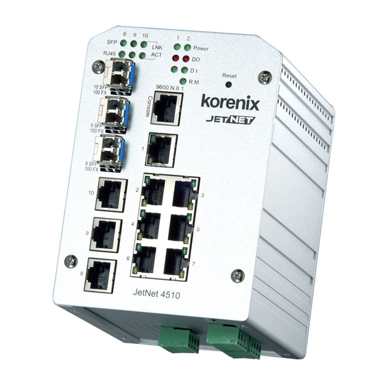
Page 9: Panel Layout
Panel Layout The front panel includes 10/100Mbps Fast Ethernet ports, SFP slot, RS232 console port, System / Combo Port LED and Reset button. Bottom View The bottom view of the JetNet 4510 Industrial Managed Switch consists of three terminal block connectors with two DC power inputs, two Digital Inputs, two Relay Outputs and 1 Earth Ground. -
Page 10: Wiring Power Inputs
Wiring Power Inputs Follow below steps to wire JetNet 4510 redundant DC power inputs. Insert positive and negative wires into V+ and V- contacts respectively of the terminal block connector Tighten the wire-clamp screws to prevent DC wires from being loosened. Power 1 and Power 2 support power redundancy and polarity reverse protection functions. -
Page 11: Wiring Digital Input
Note1: It is a good practice to turn off input and load power, and unplug power terminal block before making wire connections. Otherwise, your screwdriver blade can inadvertently short your terminal connections to the grounded enclosure. Note 2: The range of the suitable electric wire is from 12 to 24 AWG. Note 3: If the 2 power inputs are connected, JetNet 4510 will be powered from the highest connected voltage. -
Page 12: Wiring Earth Ground
Wiring Earth Ground To ensure the system will not be damaged by noise or any electrical shock, we suggest you to make exact connection between JetNet 4510 and Earth ground. On the bottom side of JetNet 4510, there is one grounding screw. Loosen the screw by screw drive;... -
Page 13: Wiring Combo Ports
Base-T and 100 Base-TX. The speed of the SFP port supports 100 Base-FX. The SFP ports accept standard MINI GBIC SFP transceiver. But, to ensure system reliability, Korenix recommends using the Korenix certificated SFP Transceiver. The certificated SFP transceiver which JetNet 4510 supported includes 100 Base-FX single/multi mode range from 550m to 80KM. -
Page 14: Wiring Rs-232 Console Cable
Wiring RS-232 Console Cable Korenix attaches one RS-232 DB9 to RJ-45 cable in the box. Connect the DB9 connector to the COM port of your PC, open Terminal tool and set up serial settings to 9600, N,8,1. -
Page 15: Din-Rail Mounting Installation
DIN-Rail Mounting Installation The DIN-Rail clip is already attached to the JetNet 4510 when packaged. If the DIN-Rail clip is not screwed on the JetNet 4510, follow the instructions and the figure below to attach DIN-Rail clip to JetNet 4510. 1. - Page 16 Lightly push the bottom of DIN-Rail clip into the track. Check if DIN-Rail clip is tightly attached on the track. To remove JetNet 4510 from the track, reverse the steps above. Notes: The DIN Rail should compliance with DIN EN50022 standard. Using wrong DIN rail may cause system install unsafe.
-
Page 17: Wall-Mounting Installation
2.10 Wall-Mounting Installation Follow the steps below to install JetNet 4510 with the wall mounting plate. 1. To remove DIN-Rail clip from JetNet 4510, loosen the screws from DIN-Rail clip. 2. Place the wall mounting plate on the rear panel of JetNet 4510. 3. -
Page 18: Preparation For Management
3.3 Preparation for Telnet console Preparation for Serial Console In JetNet 4510 package, Korenix attached one RS-232 DB-9 to RJ-45 console cable. Please attach RS-232 DB-9 connector to your PC COM port, connect RJ-45 to the Console port of the JetNet 4510. If you lose the cable, please follow the console cable PIN assignment to find one. -
Page 19: Preparation For Web Interface
3.2.1 Web Interface Korenix web management page is developed by JAVA. It allows you to use a standard web-browser such as Microsoft Internet Explorer, or Mozilla, to configure and interrogate the switch from anywhere on the network. Before you attempt to use the embedded web interface to manage switch operation,... - Page 20 3.2.2 Secured Web Interface Korenix web management page also provides secured management HTTPS login. All the configuration commands will be secured and will be hard for the hackers to sniff the login password and configuration commands.
-
Page 21: Preparation For Telnet Console
3.3.1 Telnet Korenix JetNet 4510 supports Telnet console. You can connect to the switch by Telnet and the command lines are the same as what you see by RS232 console port. Below are the steps to open Telnet connection to the switch. - Page 22 1. Open SSH Client/PuTTY In the Session configuration, enter the Host Name (IP Address of your JetNet 4510) and Port number (default = 22). Choose the “SSH” protocol. Then click on “Open” to start the SSH session console. 2. After click on Open, then you can see the cipher information in the pop-up screen. Press Yes to accept the Security Alert.
- Page 23 3. After few seconds, the SSH connection to JetNet 4510 is opened. You can see the login screen as the below figure. 4. Type the Login Name and its Password. The default Login Name and Password are admin / admin. 5.
-
Page 24: Feature Configuration
Then you can remotely connect to its embedded HTML web pages or Telnet console. Korenix web management page is developed by JAVA. It allows you to use a standard web-browser such as Microsoft Internet Explorer, or Mozilla, to configure and interrogate the switch from anywhere on the network. -
Page 25: Command Line Interface Introduction
Command Line Interface Introduction The Command Line Interface (CLI) is the user interface to the switch’s embedded software system. You can view the system information, show the status, configure the switch and receive a response back from the system by keying in a command. There are some different command modes. - Page 26 Global Configuration Mode: Press configure terminal in privileged EXEC mode. You can then enter global configuration mode. In global configuration mode, you can configure all the features that the system provides you. Type interface IFNAME/VLAN to enter interface configuration mode, exit to leave. ? to see the command list.
- Page 27 Available command lists of the global configuration mode. Switch(config)# interface fa1 Switch(config-if)# acceptable Configure 802.1Q acceptable frame types of a port. auto-negotiation Enable auto-negotiation state of a given port description Interface specific description duplex Specify duplex mode of operation for a port End current mode and change to enable mode exit Exit current mode and down to previous mode...
- Page 28 Summary of the 5 command modes. Command Main Function Enter and Exit Method Prompt Mode Enter: Login successfully User EXEC This is the first level of access. Switch> Exit: exit to logout. User can ping, telnet remote Next mode: Type enable to device, and show some basic information enter privileged EXEC mode.
- Page 29 Here are some useful commands for you to see these available commands. Save your time in typing and avoid typing error. ? To see all the available commands in this mode. It helps you to see the next command you can/should type as well. Switch(config)# interface (?) IFNAME Interface's name vlan...
-
Page 30: Basic Setting
Basic Setting The Basic Setting group provides you to configure switch information, IP address, User name/Password of the system. It also allows you to do firmware upgrade, backup and restore configuration, reload factory default, and reboot the system. Following commands are included in this group: 4.2.1 Switch Setting 4.2.2 Admin Password 4.2.3 IP Configuration... - Page 31 address or other information of the administrator. The available characters you can input is System OID: The SNMP object ID of the switch. You can follow the path to find its private MIB in MIB browser. (Note: When you attempt to view private MIB, you should compile private MIB files into your MIB browser first.) System Description: JetNet 4510 Industrial Management Ethernet Switch is the name of this product.
- Page 32 4.2.3 IP Configuration This function allows users to configure the switch’s IP address settings. DHCP Client: You can select to Enable or Disable DHCP Client function. When DHCP Client function is enabled, an IP address will be assigned to the switch from the network’s DHCP server.
- Page 33 Manual Setting: User can select Manual setting to change time as user want. User also can click the button “Get Time from PC” to get PC’s time setting for switch. NTP client: Select the Time Setting Source to NTP client can let device enable the NTP client service.
- Page 34 11 (GMT-06:00) Saskatchewan 12 (GMT-05:00) Bogota, Lima, Quito 13 (GMT-05:00) Eastern Time (US & Canada) 14 (GMT-05:00) Indiana (East) 15 (GMT-04:00) Atlantic Time (Canada) 16 (GMT-04:00) Caracas, La Paz 17 (GMT-04:00) Santiago 18 (GMT-03:00) NewFoundland 19 (GMT-03:00) Brasilia 20 (GMT-03:00) Buenos Aires, Georgetown 21 (GMT-03:00) Greenland 22 (GMT-02:00) Mid-Atlantic 23 (GMT-01:00) Azores...
- Page 35 69 (GMT+10:00) Hobart 70 (GMT+10:00) Vladivostok 71 (GMT+11:00) Magadan, Solomon Is., New Caledonia 72 (GMT+12:00) Aukland, Wellington 73 (GMT+12:00) Fiji, Kamchatka, Marshall Is. 74 (GMT+13:00) Nuku'alofa Daylight Saving Time: Set when Enable Daylight Saving Time start and end, During the Daylight Saving Time, the device’s time is one hour earlier than the actual time.
- Page 36 Manual Binding: JetNet 4510 provides a MAC address and IP address binding and removing function. You can type in the specified IP and MAC address then click Add to add a new MAC&IP address binding rule for a specified link partner, like PLC or any device without DHCP client function.
- Page 37 DHCP Relay Agent You can select to Enable or Disable DHCP relay agent function, and then select the modification type of option 82 field. Relay policy drop: Drops the option 82 field and do not add any option 82 field. Relay policy keep: Keeps the original option 82 field and forwards to server.
- Page 38 TFTP Server mode: In this mode, the switch acts as TFTP client. Before you do so, make sure that your TFTP server is ready. Then please type the IP address of TFTP Server and Backup configuration file name. This mode can be used in both CLI and Web UI. TFTP Server IP Address: You need to key in the IP address of your TFTP Server here.
- Page 39 4.2.7 Firmware Upgrade In this section, you can update the latest firmware for your switch. Korenix provides the latest firmware in Korenix Web site. The new firmware may include new features, bug fixes or other software changes. We’ll also provide the release notes for the update as well. For technical viewpoint, we suggest you use the latest firmware before installing the switch to the customer site.
- Page 40 TFTP Server mode: In this mode, the switch acts as the TFTP client. Before you do so, make sure that your TFTP server is ready. And then please type the IP address of TFTP Server IP address. This mode can be used in both CLI and Web UI. TFTP Server IP Address: You need to key in the IP address of your TFTP Server here.
- Page 41 4.2.8 Factory Default In this section, you can reset all the configurations of the switch to default setting. Click on Reset the system will then reset all configurations to default setting. The system will show you pop-up message window after finishing this command. Default setting will work after rebooting the switch.
- Page 42 to reboot the system. Click on Reboot to reboot your device. Note: Remember to click on Save button to save your settings. Otherwise, the settings you made will be gone when the switch is powered off. Figure 4.2.8.1 Main screen for Rebooting Figure 4.2.8.2 Pop-up alert screen to request confirmation.
- Page 43 Switch(config)# hostname System Name WORD Network name of this system Switch(config)# hostname JN4510 Switch(config)# Switch(config)# snmp-server location Taipei System Location Switch(config)# snmp-server contact korecare@korenix.com System Contact Switch# show snmp-server name Display JN4510 Switch# show snmp-server location Taipei Switch# show snmp-server contact korecare@korenix.com...
- Page 44 Switch(config)# ntp peer NTP Server enable disable primary secondary Switch(config)# ntp peer primary IPADDR Switch (config)# ntp peer primary 192.168.10.120 Switch(config)# clock timezone 26 Time Zone Sun Jan 1 04:13:24 2006 (GMT) Greenwich Mean Time: Dublin, Edinburgh, Lisbon, London Note: By typing clock timezone ?, you can see the timezone list.
- Page 45 default-router:192.168.17.254 lease time:300 Excluded Address List IP Address --------------- (list excluded address) Manual Binding List IP Address MAC Address --------------- -------------- (list IP & MAC binding entry) Leased Address List IP Address MAC Address Leased Time Remains --------------- -------------- -------------------- (list leased Time remain information for each entry) Backup and Restore Switch# copy startup-config tftp: 192.168.10.33/default.conf...
-
Page 46: Port Configuration
Port Configuration Port Configuration group enables you to enable/disable port state, or configure port auto-negotiation, speed, duplex, flow control, rate limit control and port aggregation settings. It also allows you to view port status and aggregation information. Following commands are included in this group: 4.3.1 Port Control 4.3.2 Port Status 4.3.3 Rate Control... - Page 47 Duplex(10 Half), 100M Full Duplex(100 Full), 100M Half Duplex(100 Half). The default mode is Auto Negotiation mode. In Flow Control column, “Symmetric” means that you need to activate the flow control function of the remote network device in order to let the flow control of that corresponding port on the switch to work.
- Page 48 The UI can display vendor name, wave length and distance of all Korenix SFP transceiver family. If you see Unknown info, it may mean that the vendor doesn’t provide their information or that the information of their transceiver can’t be read.
- Page 49 The aggregated ports can interconnect to the other switch which also supports Port Trunking. Korenix Supports 2 types of port trunking. One is Static Trunk, the other is 802.3ad. When the other end uses 802.3ad LACP, you should assign 802.3ad LACP to the trunk.
- Page 50 Trunk Size: The switch can support up to 5 trunk groups. Each trunk group can support up to 8 member ports. Since the member ports should use same speed/duplex, max groups for 100M ports would be 10. Group ID: Group ID is the ID for the port trunking group. Ports with same group ID are in the same group.
- Page 51 Group ID: Display Trunk 1 to Trunk 5 set up in Aggregation Setting. Type: Static or LACP set up in Aggregation Setting. Aggregated: When LACP links well, you can see the member ports in Aggregated column. Individual: When LACP is enabled, member ports of LACP group which are not connected to correct LACP member ports will be displayed in the Individual column.
- Page 52 Switch(config)# interface gigabitethernet10 eject port 10 SFP DDM transceiver. Switch(config-if)# sfp ddm eject DDM SFP on Port 10 normally ejected. Port Control – Auto Switch(config)# interface fa1 Negotiation Switch(config-if)# auto-negotiation Auto-negotiation of port 1 is enabled! Port Control – Force Switch(config-if)# speed 100 Speed/Duplex Port1 Link Change to DOWN...
- Page 53 Note: Administrative Status -> Port state of the port. Operating status -> Current status of the port. Duplex -> Duplex mode of the port. Speed -> Speed mode of the port. Flow control -> Flow Control status of the port. Rate Control Switch(config-if)# rate-limit Rate Control –...
- Page 54 ----- ----------- -------- -------- ------- 0x45 0x45 0x45 LACP group 2 is inactive LACP group 3 is inactive LACP group 4 is inactive Switch# show trunk group 1 Display - Trunk FLAGS: I -> Individual P -> In channel D -> Port Down Trunk Group GroupID Protocol Ports --------+---------+------------------------------------...
-
Page 55: Network Redundancy
MultiRing Technology. The Ring ports can be LACP/Port Trunking ports, after aggregated ports to a group, the group of ports can act as the Ring port of the Ring. This is Korenix Pattened TrunkRing Technology Advanced Rapid Dual Homing (RDH) technology also facilitates JetNet 4510 to connect with a core managed switch easily and conveniently. - Page 56 The new Network Redundancy Configuration/Information tree of Web UI is applied to the series of JetNet 5010G/4510 firmware V2.4. The STP Configuraiton, STP Port Configuration and STP Information pages are available while select the STP and RSTP mode. The MSTP Configuraiton, MSTP Port Configuration and MSTP Information pages are available while select the MSTP mode.
- Page 57 Bridge Configuration Bridge Address: This shows the switch’s MAC address. Priority (0-61440): RSTP uses bridge ID to determine the root bridge, the bridge with the highest bridge ID becomes the root bridge. The bridge ID is composed of bridge priority and bridge MAC address.
- Page 58 Path Cost: Enter a number between 1 and 200,000,000. This value represents the “cost” of the path to the other bridge from the transmitting bridge at the specified port. Priority: Enter a value between 0 and 240, using multiples of 16. This is the value that decides which port should be blocked by priority in a LAN.
- Page 59 4.4.3 RSTP Info (The same as previous version of user manual) This page allows you to see the information of the root switch and port status. Root Information: You can see root Bridge ID, Root Priority, Root Port, Root Path Cost and the Max Age, Hello Time and Forward Delay of BPDU sent from the root switch.
- Page 60 The figure shows there are 2 VLANs/MSTP Instances and each instance has its Root and forwarding paths. A Common Spanning Tree (CST) interconnects all adjuacent MST regions and acts as a virtual bridge node for communications with STP or RSTP nodes in the global network. MSTP connects all bridges and LAN segments with a single Common and Internal Spanning Tree (CIST).
- Page 61 After enabled MSTP mode, then you can go to the MSTP Configuraiton pages. MSTP Region Configuration This page allows configure the Region Name and its Revision, mapping the VLAN to Instance and check current MST Instance configuration. The network can be divided virtually to different Regions.
- Page 62 Instance ID: Select the Instance ID, the available number is 1-15. VLAN Group: Type the VLAN ID you want mapping to the instance. Instance Priority: Assign the priority to the instance. After finish your configuration, click on Add to apply your settings. Current MST Instance Configuration This page allows you to see the current MST Instance Configuration you added.
- Page 63 Path Cost: Enter a number between 1 and 200,000,000. This value represents the “cost” of the path to the other bridge from the transmitting bridge at the specified port. Priority: Enter a value between 0 and 240, using multiples of 16. This is the value that decides which port should be blocked by priority in a LAN.
- Page 64 Multiple Super Ring (MSR) technology is Korenix’s 3 generation Ring redundancy technology. This is patented and protected by Korenix and is used in countries all over the world. MSR ranks the fastest restore and failover time in the world, 0 ms for restore and about milliseconds level for failover for 100Base-TX copper port.
- Page 65 Ring Port2: Assign another port for ring connection Path Cost: Change the Path Cost of Ring Port2 Rapid Dual Homing: Rapid Dual Homing is an important feature of Korenix 3 generation Ring redundancy technology. When you want to connect multiple RSR or form redundant topology with other vendors,RDH could allow you to have maximum 7 multiple links for redundancy without any problem.
- Page 66 Ring status: To enable/disable the Ring. Please remember to enable the ring after you add it. 4.4.8 Ring Info This page shows you RSR information. ID: Ring ID. Version: which version of this ring, this field could be Rapid Super Ring, Super Ring or AnyRing.
- Page 67 Region Configuration Region Name: Switch(config-mst)# name NAME the name string Switch(config-mst)# name korenix Region Revision: Switch(config-mst)# revision <0-65535> the value of revision Switch(config-mst)# revision 65535 Mapping Instance to Switch(config-mst)# instance VLAN (Ex: Mapping <1-15>...
- Page 68 Configuraion Current MST configuration Name [korenix] Revision 65535 Instance Vlans Mapped -------- -------------------------------------- 1,4-4094 ------------------------------------------------ Config HMAC-MD5 Digest: 0xB41829F9030A054FB74EF7A8587FF58D ------------------------------------------------ Remove Region Switch(config-mst)# no Name name name configure revision revision configure instance the mst instance Switch(config-mst)# no name Remove Instance...
- Page 69 Port Configuration Mode Port Configuraiton Switch(config)# interface fa1 Switch(config-if)# spanning-tree bpdufilter a secure BPDU process on edge-port interfcae bpduguard a secure response to invalid configurations(received BPDU sent by self) cost change an interafce's spanning-tree port path cost edge-port interface attached to a LAN segment that is at the end of a bridged LAN or to an end node link-type the link type for the Rapid Spanning Tree...
- Page 70 TCN : sent 0 , received 0 Forwarding-State Transmit count Message-Age Expired count MSTP Information MSTP Configuraiton Switch# show spanning-tree mst configuration Current MST configuration (MSTP is Running) Name [korenix] Revision 65535 Instance Vlans Mapped -------- -------------------------------------- 1,4-4094 ------------------------------------------------ Config HMAC-MD5 Digest: 0xB41829F9030A054FB74EF7A8587FF58D...
- Page 71 Information ###### MST01 vlans mapped: 2 Bridge address 0012.77ee.eeee priority 32768 (sysid 1) Root this switch for MST01 Port Role State Cost Prio.Nbr Type ------ ---------- ---------- -------- ---------- ------------------ fa1 Designated Forwarding 200000 128.1 P2P Internal(MSTP) fa2 Designated Forwarding 200000 128.2 P2P Internal(MSTP)
- Page 72 IFNAME Interface name, ex: fastethernet1 or gi8 Switch(config-multiple-super-ring)# rapid-dual-homing port fa3,fa5-6 set Rapid Dual Homing port success. Note: auto-detect is recommended for dual Homing.. Ring Info Ring Info Switch# show multiple-super-ring [Ring ID] [Ring1] Ring1 Current Status : Disabled Role : Disabled Ring Status : Abnormal...
-
Page 73: Vlan
Figure 4.5.1 802.1Q VLAN QinQ In JetNet 4510 firmware V2.4, Korenix release extended VLAN feature, QinQ. The QinQ is originally designed to expand the number of VLANs by adding a tag to the 802.1Q packets. The original VLAN is usually identified as Customer VLAN (C-VLAN) and the new added tag - as Service VLAN(S-VLAN). - Page 74 security. VLAN Configuration group enables you to Add/Remove VLAN, configure QinQ, port Ingress/Egress parameters and view VLAN table. VLAN Configuration group enables you to Add/Remove VLAN, configure port Ingress/Egress parameters and view VLAN table. Following commands are included in this group: 4.5.1 VLAN Port Configuration 4.5.2 VLAN Configuration 4.5.3 GVRP Configuration...
- Page 75 PVID: The abbreviation of the Port VLAN ID. Enter port VLAN ID here. PVID allows the switches to identify which port belongs to which VLAN. To keep things simple, it is recommended that PVID is equivalent to VLAN IDs. The values of PVIDs are from 0 to 4095. But, 0 and 4095 are reserved. You can’t input these 2 PVIDs.
- Page 76 4.5.2 VLAN Configuration In this page, you can assign Management VLAN, create the static VLAN, and assign the Egress rule for the member ports of the VLAN. Figure 4.5.2.1 Web UI of the VLAN Configuration. Management VLAN ID: The switch supports management VLAN. The management VLAN ID is the VLAN ID of the CPU interface so that only member ports of the management VLAN can ping and access the switch.
- Page 77 Note: Before you change the management VLAN ID by Web and Telnet, remember that the port attached by the administrator should be the member port of the management VLAN; otherwise the administrator can’t access the switch via the network. Note: Currently JetNet 4510 only support max 64 group VLAN. Static VLAN Configuration You can see the created VLANs and specify the egress (outgoing) port rule to be Untagged or Tagged here.
- Page 78 want to remove one VLAN, select the VLAN entry. Then press Remove button. 4.5.3 GVRP configuration GVRP allows users to setup VLANs automatically rather than manual configuration on every port of every switch in the network. GVRP Protocol: Allow user to enable/disable GVRP globally. State: After enable GVRP globally, Here still can enable/disable GVRP by port.
- Page 79 VLAN ID: ID of the VLAN. Name: Name of the VLAN. Status: Static shows this is a manually configured static VLAN. Unused means this VLAN is created by UI/CLI and has no member ports. This VLAN is not workable yet. Dynamic means this VLAN is learnt by GVRP.
- Page 80 Switch(config-if)# acceptable frame type vlantaggedonly only vlan-tag frame is accepted! Ingress Filtering (for Switch(config-if)# ingress filtering enable fast Ethernet port 1) ingress filtering enable Switch(config-if)# ingress filtering disable ingress filtering disable Egress rule – Untagged Switch(config-if)# switchport access vlan 2 (for VLAN 2) switchport access vlan - success Egress rule –...
- Page 81 vlan learning independent ……… ……… interface fastethernet5 switchport access vlan add 1-2,10 switchport dot1q-tunnel mode access interface fastethernet6 switchport access vlan add 1-2 switchport trunk allowed vlan add 10 switchport dot1q-tunnel mode uplink VLAN Configuration Create VLAN (2) Switch(config)# vlan 2 vlan 2 success Switch(config)# interface vlan 2 Switch(config-if)#...
- Page 82 VLAN1 Static fa1-7,fa8-10 VLAN2 Unused test Static fa4-7,fa8-10 fa1-3,fa7,fa8-10 Display – VLAN Switch# show interface vlan1 interface information interface vlan1 is up, line protocol detection is disabled index 14 metric 1 mtu 1500 <UP,BROADCAST,RUNNING,MULTICAST> HWaddr: 00:12:77:ff:01:b0 inet 192.168.10.100/24 broadcast 192.168.10.255 input packets 639, bytes 38248, dropped 0, multicast packets 0 input errors 0, length 0, overrun 0, CRC 0, frame 0, fifo 0, missed 0 output packets 959, bytes 829280, dropped 0...
-
Page 83: Private Vlan
Private VLAN The private VLAN helps to resolve the primary VLAN ID shortage, client ports’ isolation and network security issues. The Private VLAN provides primary and secondary VLAN within a single switch. Primary VLAN: The uplink port is usually the primary VLAN. A primary VLAN contains promiscuous ports that can communicate with lower Secondary VLANs. - Page 84 communicate with each other. 4.6.2 PVLAN Port Configuration PVLAN Port Configuration page allows configure Port Configuration and Private VLAN Association. Private VLAN Association Secondary VLAN: After the Isolated and Community VLAN Type is assigned in Private VLAN Configuration page, the VLANs are belonged to the Secondary VLAN and displayed here.
- Page 85 For example: 1. VLAN Create: VLAN 2-5 are created in VLAN Configuration page. 2. Private VLAN Type: VLAN 2-5 has its Private VLAN Type configured in Private VLAN Configuration page. VLAN 2 is belonged to Primary VLAN. VLAN 3-5 are belonged to secondary VLAN (Isolated or Community). 3.
- Page 86 4.6.3 Private VLAN Information This page allows you to see the Private VLAN information. 4.6.4 CLI Command of the PVLAN Command Lines of the Private VLAN configuration Feature Command Line Private VLAN Configuration Create VLAN Switch(config)# vlan 2 vlan 2 success Switch(config-vlan)# End current mode and change to enable mode exit...
- Page 87 Primary Type Switch(config-vlan)# private-vlan primary <cr> Isolated Type Switch(config-vlan)# private-vlan isolated <cr> Community Type Switch(config-vlan)# private-vlan community <cr> Private VLAN Port Configuraiton Go to the port Switch(config)# interface (port_number, ex: gi9) configuraiton Switch(config-if)# switchport private-vlan host-association Set the private VLAN host association mapping map primary VLAN to secondary VLAN Private VLAN Port Type...
- Page 88 Vlan Type Ports ---- ----------------- ----------------- primary gi10 isolated community community fa7,gi9 primary Host List Switch# show vlan private-vlan port-list Ports Mode Vlan ----- ----------- ---- normal normal normal normal normal normal host host host promiscuous 2 Running Config Switch# show run Information Building configuration...
- Page 89 switchport trunk native vlan 5 switchport mode private-vlan host switchport private-vlan host-association 2 3 interface gigabitethernet10 switchport access vlan add 2,5 switchport trunk native vlan 2 switchport mode private-vlan promiscuous switchport private-vlan mapping 2 add 3-5 ……… ……..
-
Page 90: Traffic Prioritization
Traffic Prioritization Quality of Service (QoS) provides traffic prioritization mechanism which allows users to deliver better service to certain flows. QoS can also help to alleviate congestion problems and ensure high-priority traffic is delivered first. This section allows you to configure Traffic Prioritization settings for each port with regard to setting priorities. - Page 91 In JetNet, users can freely assign the mapping table or follow the suggestion of the 802.1p standard. Korenix uses 802.p suggestion as default values. You can find CoS values 1 and 2 are mapped to physical Queue 0, the lowest queue. CoS values 0 and 3 are mapped to physical Queue 1, the low/normal physical queue.
- Page 92 4.7.3 DSCP-Queue Mapping This page is to change DSCP values to Physical Queue mapping table. Since the switch fabric of JetNet only supports 4 physical queues, Lowest, Low, Middle and High. Users should therefore assign how to map DSCP value to the level of the physical queue. In JetNet, users can freely change the mapping table to follow the upper layer 3 switch or routers’...
- Page 93 Switch(config-if)# qos cos 7 The default port CoS value is set 7 ok. Note: When change the port setting, you should Select the specific port first. Ex: fa1 means fast Ethernet port 1. Port Setting – Trust Switch(config)# interface fa1 Mode- CoS Only Switch(config-if)# qos trust cos The port trust is set CoS only ok.
- Page 94 Map CoS 0 to Queue 1 Switch(config)# qos cos-map 0 1 The CoS to queue mapping is set ok. Map CoS 1 to Queue 0 Switch(config)# qos cos-map 1 0 The CoS to queue mapping is set ok. Map CoS 2 to Queue 0 Switch(config)# qos cos-map 2 0 The CoS to queue mapping is set ok.
-
Page 95: Multicast Filtering
Multicast Filtering For multicast filtering, JetNet 4510 uses IGMP Snooping technology. IGMP (Internet Group Management Protocol) is an Internet Protocol that provides a way for internet device to report its multicast group membership to adjacent routers. Multicasting allows one computer on the internet to send data to a multitude of other computers that have identified themselves as being interested in receiving the originating computers data. - Page 96 Disable IGMP Snooping for certain VLANs. IGMP Snooping Table: In the table, you can see multicast group IP address, VLAN ID it belongs to, and member ports of the multicast group. JetNet 4510 supports 256 multicast groups. Click on Reload to refresh the table.
- Page 97 4.8.2 IGMP Query This page allows users to configure IGMP Query feature. Since JetNet 4510 can only be configured by member ports of the management VLAN, IGMP Query can only be enabled on the management VLAN. If you want to run IGMP Snooping feature in several VLANs, you should notice that whether each VLAN has its own IGMP Querier first.
- Page 98 Feature Command Line IGMP Snooping IGMP Snooping - Switch(config)# ip igmp snooping Global IGMP snooping is enabled globally. Please specify on which vlans IGMP snooping enables IGMP Snooping - VLAN Switch(config)# ip igmp snooping vlan VLANLIST allowed vlan list all existed vlan Switch(config)# ip igmp snooping vlan 1-2 IGMP snooping is enabled on VLAN 1-2.
- Page 99 ……. Force filtering Enable Force filtering Switch(config)# mac-address-table multicast filtering Filtering unknown multicast addresses ok! Disable Force filtering Switch(config)# no mac-address-table multicast filtering Flooding unknown multicast addresses ok!
-
Page 100: Snmp
SNMP Simple Network Management Protocol (SNMP) is a protocol used for exchanging management information between network devices. SNMP is a member of the TCP/IP protocol suite. JetNet 4510 series support SNMP v1, v2c.and V3 An SNMP managed network consists of two main components: agents and a manager. - Page 101 4.9.2 SNMPv3 Profile SNMP v3 can provide more security functions when the user performs remote management through SNMP protocol. It delivers SNMP information to the administrator with user authentication; all of data between JetNet 4510 and the administrator are encrypted to ensure secure communication. Security Level: Here the user can select the following levels of security: None, User Authentication, and Authentication with privacy.
- Page 102 This page allows users to Enable SNMP Trap, configure the SNMP Trap server IP, Community name, and trap Version V1 or V2. After configuration, you can see the change of the SNMP pre-defined standard traps and Korenix pre-defined traps. The pre-defined traps can be found in Korenix private MIB.
- Page 103 community string add ok Read Write Community Switch(config)# snmp-server community private rw community string add ok SNMP Trap Enable Trap Switch(config)# snmp-server enable trap Set SNMP trap enable ok. SNMP Trap Server IP Switch(config)# snmp-server host 192.168.10.33 without specific SNMP trap host add OK. community name SNMP Trap Server IP Switch(config)# snmp-server host 192.168.10.33 version 1...
-
Page 104: Security
4.10 Security JetNet 4510 provides several security features for you to secure your connection. The features include Port Security and IP Security. Following commands are included in this group: 4.10.1 Port Security 4.10.2 IP Security 4.10.3 IEEE 802.1x 4.10.4 CLI Commands of the Security 4.10.1 Port Security Port Security feature allows you to stop the MAC address learning for specific port. - Page 105 4.10.2 IP Security In IP Security section, you can set up specific IP addresses to grant authorization for management access to this JetNet via a web browser or Telnet. IP Security: Select Enable and Apply to enable IP security function. Add Security IP: You can assign specific IP addresses, and then press Add.
- Page 106 IEEE 802.1X is the protocol that performing authentication to obtain access to IEEE 802 LANs. It is port-base network access control. With the function, JetNet 4510 could control which connection is available or not. System Auth Control: To enable or disable the 802.1x authentication. Authentication Method: Radius is a authentication server that provide key for authentication, with this method, user must connect switch to server.
- Page 107 4.9.3.2 802.1x Port Configuration Port control: Force Authenorized means this port is Authenorized, the data is free to in/out. Force unauthenorized just opposite, the port is blocked. If users want to control this port with Radius Server, please select Auto for port control. Reauthentication: If enable this field, switch will ask client to re-authenticate.
- Page 108 Once you finish configuring the settings, click on Apply to apply your configuration. Click Initialize Selected to set the authorize state of selected port to initialize status. Click Reauthenticate Selected to send EAP Request to supplicant to request reauthentication. Click Default Selected to reset the configurable 802.1x parameters of selected port to the default values.
- Page 109 then enable the port security to stop new MAC learning. Disable Port Security Switch(config-if)# no switchport port-security Enable new MAC addresses learning and aging activities! Display Switch# show mac-address-table static Destination Address Address Type Vlan Destination Port ------------------- --------------- ------- ------------------------ 0012.7701.0101 Static IP Security...
- Page 110 Secondary RADIUS Server Key : 5678 Secondary RADIUS Server Port : 1812 Secondary RADIUS Accounting Port : 1813 User name/password Switch(config)# dot1x username korenix passwd korenix vlan for authentication...
-
Page 111: Warning
4.11 Warning JetNet 4510 provides several types of Warning features for you to remote monitor the status of end devices or the change of your network. The features include Fault Relay, System Log and SMTP E-mail Alert. Following commands are included in this group: 4.11.1 Fault Relay 4.11.2 Event Selection 4.11.3 Syslog Configuration... - Page 112 How to configure: Select the DI Number you want to monitor and DI State, High or Low. For example: When DI 1 and High are selected, it means when DI 1 is pulled high, the system will short Relay Output and light DO LED. Event Type: Dry Output On Period (Sec): Type the period time to turn on Relay Output.
- Page 113 Power ID: Select Power 1 or Power 2 you want to monitor. When the power is shut down or broken, the system will short Relay Out and light the DO LED. Event Type: Like Failure Link: Select the port ID you want to monitor. How to configure: Select the checkbox of the Ethernet ports you want to monitor.
- Page 114 If the ping failure occurred, the switch system will turn Relay output to open state to emulate power switch off for 5 sec periods. After Reset Time timeout, the Switch system will start ping target device after 50 sec periods. The period time is for target device system booting.
- Page 115 Once you finish configuring the settings, click on Apply to apply your configuration. 4.11.3 SysLog Configuration System Log is useful to provide system administrator locally or remotely monitor switch events history. There are 2 System Log modes provided by JetNet 4510, local mode and remote mode.
- Page 116 Once you finish configuring the settings, click on Apply to apply your configuration. Note: When enabling Local or Both mode, you can monitor the system logs in [Monitor and Diag] / [Event Log] page. 4.11.4 SMTP Configuration JetNet 4510 supports E-mail Warning feature. The switch will send the occurred events to remote E-mail server.
- Page 117 Field Description SMTP Server IP Address Enter the IP address of the email Server Authentication Click on check box to enable password User Name Enter email Account name (Max.40 characters) Password Enter the password of the email account Confirm Password Re-type the password of the email account You can set up to 4 email addresses to receive email alarm from JetNet Rcpt E-mail Address 1...
- Page 118 <cr> reset reset a device Switch(config)# relay 1 ping 192.168.10.33 reset <1-65535> reset time Switch(config)# relay 1 ping 192.168.10.33 reset 60 <0-65535> hold time to retry Switch(config)# relay 1 ping 192.168.10.33 reset 60 60 Port Link Failure Switch(config)# relay 1 port PORTLIST port list Switch(config)# relay 1 port fa1-5 Power Failure...
- Page 119 SMTP Email Alert set Server: 192.168.10.100, Account: admin@192.168.10.100 ok. Receiver mail Switch(config)# smtp-server receipt 1 korecare@192.168.10.100 SMTP Email Alert set receipt 1: korecare@korenix.com ok. Authentication with Switch(config)# smtp-server authentication username admin username and password admin password SMTP Email Alert set authentication Username: admin, Password: admin Note: You can assign string to username and password.
-
Page 120: Monitor And Diag
4.12 Monitor and Diag JetNet 4510 provides several types of features for you to monitor the status of the switch or diagnostic for you to check the problem when encountering problems related to the switch. The features include MAC Address Table, Port Statistics, Port Mirror, Event Log and Ping. - Page 121 4.12.2 Port Statistics In this page, you can view operation statistics for each port. The statistics that can be viewed include Link Type, Link State, Rx Good, Rx Bad, Rx Abort, Tx Good, Tx Bad and Collision. Rx means the received packet while Tx means the transmitted packets. Note: If you see many Bad, Abort or Collision counts increased, that may mean your network cable is not connected well, the network performance of the port is poor…etc.
- Page 122 4.12.3 Port Mirroring Port mirroring (also called port spanning) is a tool that allows you to mirror the traffic from one or more ports onto another port, without disrupting the flow of traffic on the original port. Any traffic that goes into or out of the Source Port(s) will be duplicated at the Destination Port.
- Page 123 4.12.4 Event Log In the 4.10.3, we have introduced System Log feature. When System Log Local mode is selected, JetNet 4510 will record occurred events in local log table. This page shows this log table. The entry includes the index, occurred data and time and content of the events. Click on Clear to clear the entries.
- Page 124 4.12.6 CLI Commands of the Monitor and Diag Command Lines of the Monitor and Diag configuration Feature Command Line MAC Address Table Ageing Time Switch(config)# mac-address-table aging-time 350 mac-address-table aging-time set ok! Note: 350 is the new ageing timeout value. Add Static Unicast MAC Switch(config)# mac-address-table static 0012.7701.0101 address...
-
Page 125: Port Mirroring
------------------- --------------- ------- ------------------------ 0012.7710.0101 Static 0012.7710.0102 Static Show Aging timeout Switch# show mac-address-table aging-time time the mac-address-table aging-time is 300 sec. Port Statistics Port Statistics Switch# show rmon statistics fa4 (select interface) Interface fastethernet4 is enable connected, which has Inbound: Good Octets: 178792, Bad Octets: 0 Unicast: 598, Broadcast: 1764, Multicast: 160... - Page 126 64 bytes from 192.168.10.33: icmp_seq=3 ttl=128 time=0.0 64 bytes from 192.168.10.33: icmp_seq=4 ttl=128 time=0.0 --- 192.168.10.33 ping statistics --- packets transmitted, 5 packets received, 0% packet loss round-trip min/avg/max = 0.0/0.0/0.0 ms...
-
Page 127: Device Front Panel
4.12 Device Front Panel Device Front Panel allows you to see LED status of the switch. You can see LED and link status of the Power, DO, DI, R.M. and Ports. Feature On / Link UP Off / Link Down Other Power Green... -
Page 128: Save To Flash
4.13 Save to Flash Save Configuration allows you to save any configuration you just made to the Flash. Powering off the switch without clicking on Save Configuration will cause loss of new settings. After selecting Save Configuration, click on Save to Flash to save your new configuration. -
Page 129: Logout
4.14 Logout The switch provides 2 logout methods. The web connection will be logged out if you don’t input any command after 30 seconds. The Logout command allows you to manually logout the web connection. Click on Yes to logout, No to go back the configuration page. Command Lines: Feature Command Line... -
Page 130: Appendix
5 Appendix Product Specification. Note: Please refer to the latest datasheet. You can download from the web site Technology Standard IEEE 802.3 10Base-T Ethernet IEEE 802.3u 100Base-TX Fast Ethernet IEEE 802.3x Flow Control and Back-pressure IEEE 802.1p class of service IEEE 802.1Q VLAN and GVRP IEEE 802.1 Q-in-Q IEEE 802.1D-2004 Rapid Spanning Tree Protocol (RSTP) - Page 131 Super Ring. The MSR supports 5ms failover time and zero second of restore time in R.M. auto selection mode, it also backward compatible with legacy super ring in slave mode. Rapdid Dual Homing generation of Korenix Dual Homing Technology. Easily...
- Page 132 (RDH configuration and connect Korenix Rapid Super Ring with any other Switch or another Ring topology. TrunkRing Provides port aggregate function in ring path to get more bandwidth for higher throughput ring architecture. MultiRing New generation of ring coupling technology without extra control port.
-
Page 133: Pin Assignment Of The Rs-232 Console Cable
-40℃ ~75℃ (-w / -NEMA model) Operating Humidity 5% ~ 95%, non-condensing Storage Temperature -40℃ ~ 85 ℃ Hi-Pot Hi-pot testing, AC 1.2 KV for port and power Regulatory Approvals EN55022 CLASS A, EN61000-3-2, EN61000-3-3, EN61000-6-4 EN55024, EN61000-6-2, IEC 61000-4-2, IEC 61000-4-3, IEC 61000-4-4, IEC 61000-4-5, IEC 61000-4-6, IEC 61000-4-8, IEC 61000-6-2 Shock... -
Page 134: Korenix Sfp Family
Korenix certificated SFP transceivers when you constructing your network. Korenix will keep on certificating and updating the certificated SFP transceivers in Korenix web site and purchase list. You can refer to the web site to get the latest information about SFP transceivers. - Page 135 Model Name 100Mbps BIDI/WDM SFP Transceiver Single mode 100Mbps, TX 1310nm/RX 1550nm, 20Km Fiber Transceiver, SFP100SM20B13 -10~70℃ Single mode 100Mbps, TX 1310nm/RX 1550nm, 20Km Fiber Transceiver, SFP100SM20B13-w -40~85℃ Single mode 100Mbps, TX 1550nm/RX 1310nm, 20Km Fiber Transceiver, SFP100SM20B15 -10~70℃ Single mode 100Mbps, TX 1550nm/RX 1310nm, 20Km Fiber Transceiver, SFP100SM20B15-w -40~85℃...
-
Page 136: Korenix Private Mib
SNMP. But, since some commands can’t be found in standard MIB, Korenix provides Private MIB to meet up the need. Compile the private MIB file by your SNMP tool. You can then use it. Private MIB can be found in product CD or downloaded from Korenix Web site. -
Page 137: Revision History
Revision History Edition Date Modifications V1.0 Jan. 18, 2008 The first version V1.1 Mar. 27, 2008 Change working temperature from -10 to -20. V2.1 June, 19, 2008 Modify for Multiple Super Ring Modify Rapid Dual Homing Modify IGMP function Add Time Synchronize Failure warning event Modify Private MIB ID V2.2 20,Jun,2008... -
Page 138: About Korenix
Less Time At Work! Fewer Budget on applications! The Korenix business idea is to let you spend less time at work and fewer budget on your applications. Do you really want to go through all the troubles but still end up with low quality products and lousy services? Definitely not! This is why you need Korenix.
Need help?
Do you have a question about the JetNet 4510 Series and is the answer not in the manual?
Questions and answers