Korenix JetNet 5010G Series User Manual
Industrial managed ethernet switch
Hide thumbs
Also See for JetNet 5010G Series:
- User manual (143 pages) ,
- Quick start manual (5 pages) ,
- Quick installation manual (28 pages)

Related Manuals for Korenix JetNet 5010G Series


Summary of Contents for Korenix JetNet 5010G Series
-
Page 1: User Manual
Korenix JetNet 5010G Series Industrial Managed Ethernet Switch User Manual Ver. 2.10, Jun-2012 Firmware v2.6 Hardware v2.3 www.korenix.com... - Page 2 Korenix JetNet 5010G Series Industrial Managed Ethernet Switch User’s Manual Copyright Notice Copyright 2007-2012 Korenix Technology Co., Ltd. All rights reserved. Reproduction in any form or by any means without permission is prohibited.
- Page 3 Federal Communications Commission (FCC) Statement This equipment has been tested and found to comply with the limits for a Class A digital device, pursuant to Part 15 of the FCC Rules. These limits are designed to provide reasonable protection against harmful interference when the equipment is operated in a commercial environment.
-
Page 4: Table Of Contents
4.13 Save to Flash ................126 4.14 Logout ..................127 5. Appendix ....................128 Pin Assignment of the RS-232 Console Cable ......128 Korenix SFP family ..............129 Korenix Private MIB ..............132 ModBus TCP /IP ................ 133 Revision History ................. 144... -
Page 5: Introduction
300ms to 5ms for 10/100TX RJ-45 ports, and 30ms for 100FX and Gigabit Fiber. This is Korenix patented ring technology, which is registered in most countries. For interoperability with your existed network, JetNet 5010G series also come with an advanced redundant network solution, Ring Coupling and Rapid Dual Homing technology. -
Page 6: Package List
C for all models Note: The detail spec is listed in Appendix 5.1. Package List Korenix JetNet 5010G Series products are shipped with following items: One industrial Managed Ethernet switch One DIN-Rail clip (attached to the switch) One wall mounting plate and 4 screws (M3 in 6 mm length) -
Page 7: Hardware Installation
2 Hardware Installation This chapter includes hardware introduction, installation and configuration information. Following topics are covered in this chapter: 2.1 Hardware Introduction Dimension Panel Layout Bottom View 2.2 Wiring Power Inputs 2.3 Wiring Digital Input 2.4 Wiring Relay Output 2.5 Wiring Ethernet Ports 2.6 Wiring Combo Ports 2.7 Wiring RS-232 console cable 2.8 DIN-Rail Mounting Installation... -
Page 8: Hardware Introduction
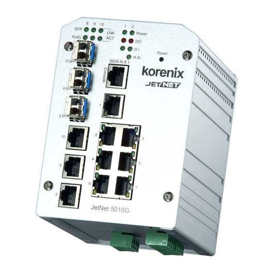
Hardware Introduction Dimension (v2.3 hardware) JetNet 5010G Industrial Gigabit Switch dimension (W x H x D) is 96mm x 137mm x 119mm... -
Page 9: Panel Layout
Panel Layout The front panel includes 10/100Mbps Fast Ethernet ports, Gigabit Ethernet ports, SFP slot, RS232 console port, System / Combo Port LED and Reset button. Bottom View The bottom view of the JetNet 5010G Industrial Gigabit Managed Switch consists of three terminal block connectors with two DC power inputs, two Digital Inputs, 2 Relay Outputs and 1 Earth Ground. -
Page 10: Wiring Power Inputs
Wiring Power Inputs Follow below steps to wire JetNet 5010G redundant DC power inputs. Insert positive and negative wires into V+ and V- contacts respectively of the terminal block connector Tighten the wire-clamp screws to prevent DC wires from being loosened. Power 1 and Power 2 support power redundancy and polarity reverse protection functions. -
Page 11: Wiring Digital Input
Wiring Digital Input JetNet 5010G provides 2 digital inputs. It allows users to connect the termination units’ digital output and manage/monitor the status of the connected unit. The Digital Input pin can be pulled high or low; thus the connected equipments can actively drive these pins high or low. -
Page 12: Wiring Fast Ethernet Ports
Wiring Fast Ethernet Ports JetNet 5010G includes 7 RJ-45 Fast Ethernet ports. The fast Ethernet ports support 10Base-T and 100Base-TX, full or half duplex modes. All the fast Ethernet ports will auto-detect the signal from connected devices to negotiate the link speed and duplex mode. -
Page 13: Wiring Combo Ports
Wiring RS-232 Console Cable Korenix attaches one RS-232 DB-9 to RJ-45 cable in the box. Connect the DB-9 connector to the COM port of your PC, open Terminal tool and set up serial settings to 9600, N,8,1. -
Page 14: Din-Rail Mounting Installation
DIN-Rail Mounting Installation The DIN-Rail clip is already attached to the JetNet 5010G when packaged. If the DIN-Rail clip is not screwed on the JetNet 5010G, follow the instructions and the figure below to attach DIN-Rail clip to JetNet 5010G. 1. - Page 15 Lightly push the bottom of DIN-Rail clip into the track. Check if DIN-Rail clip is tightly attached on the track. To remove JetNet 5010G from the track, reverse the steps above. Notes: The DIN Rail should compliance with DIN EN50022 standard. Using wrong DIN rail may cause system install unsafe.
-
Page 16: Wall-Mounting Installation
2.10 Wall-Mounting Installation Follow the steps below to install JetNet 5010G with the wall mounting plate. 1. To remove DIN-Rail clip from JetNet 5010G, loosen the screws from DIN-Rail clip. 2. Place the wall mounting plate on the rear panel of JetNet 5010G. 3. -
Page 17: Preparation For Management
3.3 Preparation for Telnet console Preparation for Serial Console In JetNet 5010G package, Korenix attached one RS-232 DB-9 to RJ-45 console cable. Please attach RS-232 DB-9 connector to your PC COM port, connect RJ-45 to the Console port of the JetNet 5010G. If you lose the cable, please follow the console cable PIN assignment to find one. -
Page 18: Preparation For Web Interface
3.2.1 Web Interface Korenix web management page is developed by JAVA. It allows you to use a standard web-browser such as Microsoft Internet Explorer, or Mozila, to configure and interrogate the switch from anywhere on the network. Before you attempt to use the embedded web interface to manage switch operation,... - Page 19 3.2.2 Secured Web Interface Korenix web management page also provides secured management HTTPS login. All the configuration commands will be secured and will be hard for the hackers to sniff the login password and configuration commands.
-
Page 20: Preparation For Telnet Console
3.3.1 Telnet Korenix JetNet 5010G supports Telnet console. You can connect to the switch by Telnet and the command lines are the same as what you see by RS232 console port. Below are the steps to open Telnet connection to the switch. - Page 21 Enter 3.3.2 SSH (Secure Shell) Korenix JetNet 5010G also support SSH console. You can remotely connect to the switch by command line interface. The SSH connection can secure all the configuration commands you sent to the switch. SSH is a client/server architecture while JetNet 5010G is the SSH server. When you want to make SSH connection with the switch, you should download the SSH client tool first.
- Page 22 3. After few seconds, the SSH connection to JetNet 5010G is opened. You can see the login screen as the below figure. 4. Type the Login Name and its Password. The default Login Name and Password are admin / admin. 5.
-
Page 23: Feature Configuration
Then you can remotely connect to its embedded HTML web pages or Telnet console. Korenix web management page is developed by JAVA. It allows you to use a standard web-browser such as Microsoft Internet Explorer, or Mozila, to configure and interrogate the switch from anywhere on the network. -
Page 24: Command Line Interface Introduction
Command Line Interface Introduction The Command Line Interface (CLI) is the user interface to the switch’s embedded software system. You can view the system information, show the status, configure the switch and receive a response back from the system by keying in a command. There are some different command modes. - Page 25 Global Configuration Mode: Press configure terminal in privileged EXEC mode. You can then enter global configuration mode. In global configuration mode, you can configure all the features that the system provides you. Type interface IFNAME/VLAN to enter interface configuration mode, exit to leave. ? to see the command list.
- Page 26 Available command lists of the global configuration mode. Switch(config)# interface fa1 Switch(config-if)# acceptable Configure 802.1Q acceptable frame types of a port. auto-negotiation Enable auto-negotiation state of a given port description Interface specific description duplex Specify duplex mode of operation for a port End current mode and change to enable mode exit Exit current mode and down to previous mode...
- Page 27 Summary of the 5 command modes. Command Main Function Enter and Exit Method Prompt Mode User EXEC This is the first level of access. Enter: Login successfully Switch> User can ping, telnet remote Exit: exit to logout. device, and show some basic Next mode: Type enable to information enter privileged EXEC mode.
- Page 28 Here are some useful commands for you to see these available commands. Save your time in typing and avoid typing error. ? To see all the available commands in this mode. It helps you to see the next command you can/should type as well. Switch(config)# interface (?) IFNAME Interface's name vlan...
-
Page 29: Basic Setting
Basic Setting The Basic Setting group provides you to configure switch information, IP address, User name/Password of the system. It also allows you to do firmware upgrade, backup and restore configuration, reload factory default, and reboot the system. Following commands are included in this group: 4.2.1 Switch Setting 4.2.2 Admin Password 4.2.3 IP Configuration... - Page 30 System Name: You can assign a name to the device. The available characters you can input is 64. After you configure the name, CLI system will select the first 12 characters as the name in CLI system. System Location: You can specify the switch’s physical location here. The available characters you can input are 64.
- Page 31 Password: You can key in new password here. The default setting is admin. Confirm Password: You need to type the new password again to confirm it. Once you finish configuring the settings, click on Apply to apply your configuration. Figure 4.2.2.2 Popup alert window for Incorrect Username. 4.2.3 IP Configuration This function allows users to configure the switch’s IP address settings.
- Page 32 Default Gateway: You can assign the gateway for the switch here. The default gateway is 192.168.10.254. Note: In CLI, we use 0.0.0.0/0 to represent for the default gateway. Once you finish configuring the settings, click on Apply to apply your configuration. 4.2.4 Time Setting Time Setting source allow user to set the time manually or through NTP server.
- Page 33 Switch(config)# clock timezone 01 (GMT-12:00) Eniwetok, Kwajalein 02 (GMT-11:00) Midway Island, Samoa 03 (GMT-10:00) Hawaii 04 (GMT-09:00) Alaska 05 (GMT-08:00) Pacific Time (US & Canada) , Tijuana 06 (GMT-07:00) Arizona 07 (GMT-07:00) Mountain Time (US & Canada) 08 (GMT-06:00) Central America 09 (GMT-06:00) Central Time (US &...
- Page 34 55 (GMT+07:00) Krasnoyarsk 56 (GMT+08:00) Beijing, Chongqing, Hong Kong, Urumqi 57 (GMT+08:00) Irkutsk, Ulaan Bataar 58 (GMT+08:00) Kuala Lumpur, Singapore 59 (GMT+08:00) Perth 60 (GMT+08:00) Taipei 61 (GMT+09:00) Osaka, Sapporo, Tokyo 62 (GMT+09:00) Seoul 63 (GMT+09:00) Yakutsk 64 (GMT+09:30) Adelaide 65 (GMT+09:30) Darwin 66 (GMT+10:00) Brisbane 67 (GMT+10:00) Canberra, Melbourne, Sydney...
- Page 35 Once you have finished the configuration, click Apply to apply your configuration Excluded Address: You can type a specific address into the IP Address field for the DHCP server reserved IP address. The IP address that is listed in the Excluded Address List Table will not be assigned to the network device.
- Page 36 It will show the MAC and IP address that was assigned by JetNet 5010G. Click the Reload button to refresh the listing. DHCP Relay Agent You can select to Enable or Disable DHCP relay agent function, and then select the modification type of option 82 field.
- Page 37 There are 2 modes for users to backup/restore the configuration file, Local File mode and TFTP Server mode. Local File mode: In this mode, the switch acts as the file server. Users can browse the target folder and then type the file name to backup the configuration. Users can also browse the target folder and select existed configuration file to restore the configuration back to the switch.
- Page 38 4.2.7 Firmware Upgrade In this section, you can update the latest firmware for your switch. Korenix provides the latest firmware in Korenix Web site. The new firmware may include new features, bug fixes or other software changes. We’ll also provide the release notes for the update as well. For technical viewpoint, we suggest you use the latest firmware before installing the switch to the customer site.
- Page 39 There are 2 modes for users to backup/restore the configuration file, Local File mode and TFTP Server mode. Local File mode: In this mode, the switch acts as the file server. Users can browse the target folder and then type the file name to backup the configuration. Users also can browse the target folder and select the existed configuration file to restore the configuration back to the switch.
- Page 40 Click on Folder icon to select the target firmware file you want to upgrade. Figure 4.2.7.3 Firmware Upgrade – TFTP Server mode. Type the IP address of TFTP Server and Firmware File Name. Then click on Upgrade to start the process. After finishing transmitting the firmware, the system will copy the firmware file and replace the firmware in the flash.
- Page 41 4.2.8 Factory Default In this section, you can reset all the configurations of the switch to default setting. Click on Reset the system will then reset all configurations to default setting. The system will show you popup message window after finishing this command. Default setting will work after rebooting the switch.
- Page 42 4.2.9 System Reboot System Reboot allows you to reboot the device. Some of the feature changes require you to reboot the system. Click on Reboot to reboot your device. Note: Remember to click on Save button to save your settings. Otherwise, the settings you made will be gone when the switch is powered off.
- Page 43 Switch(config)# hostname System Name WORD Network name of this system Switch(config)# hostname JN5010G SWITCH(config)# SWITCH(config)# snmp-server location Taipei System Location SWITCH(config)# snmp-server contact korecare@korenix.com System Contact SWITCH# show snmp-server name Display SWITCH SWITCH# show snmp-server location Taipei SWITCH# show snmp-server contact korecare@korenix.com...
- Page 44 Time Setting SWITCH(config)# ntp peer NTP Server enable disable primary secondary SWITCH(config)# ntp peer primary IPADDR SWITCH(config)# ntp peer primary 192.168.10.120 SWITCH(config)# clock timezone 26 Time Zone Sun Jan 1 04:13:24 2006 (GMT) Greenwich Mean Time: Dublin, Edinburgh, Lisbon, London Note: By typing clock timezone ?, you can see the timezone list.
- Page 45 Switch# show ip dhcp server statistics Show DHCP server Switch# show ip dhcp server statistics information DHCP Server ON Address Pool 1 network:192.168.17.0/24 default-router:192.168.17.254 lease time:300 Excluded Address List IP Address --------------- (list excluded address) Manual Binding List IP Address MAC Address --------------- -------------- (list IP &...
-
Page 46: Port Configuration
Port Configuration Port Configuration group enables you to enable/disable port state, or configure port auto-negotiation, speed, and duplex, flow control, rate limit control and port aggregation settings. It also allows you to view port status and aggregation information. Following commands are included in this group: 4.3.1 Port Control 4.3.2 Port Status 4.3.3 Rate Control... - Page 47 Half Duplex(10 Half), 100M Full Duplex(100 Full), 100M Half Duplex(100 Half), 1000M Full Duplex(1000 Full), 1000M Half Duplex(1000 Half). The default mode is Auto Negotiation mode. In Flow Control column, “Symmetric” means that you need to activate the flow control function of the remote network device in order to let the flow control of that corresponding port on the switch to work.
- Page 48 The UI can display vendor name, wave length and distance of all Korenix SFP transceiver family. If you see Unknown info, it may mean that the vendor doesn’t provide their information or that the information of their transceiver can’t be read.
- Page 49 The aggregated ports can interconnect to the other switch which also supports Port Trunking. Korenix Supports 2 types of port trunking. One is Static Trunk, the other is 802.3ad. When the other end uses 802.3ad LACP, you should assign 802.3ad LACP to the trunk.
- Page 50 Trunk Size: The switch can support up to 5 trunk groups. Each trunk group can support up to 8 member ports. Since the member ports should use same speed/duplex, max groups for 100M ports would be 7, and 3 for gigabit ports. Group ID: Group ID is the ID for the port trunking group.
- Page 51 Aggregation Status This page shows the status of port aggregation. Once the aggregation ports are negotiated well, you will see following status. Group ID: Display Trunk 1 to Trunk 5 set up in Aggregation Setting. Type: Static or LACP set up in Aggregation Setting. Aggregated: When LACP links well, you can see the member ports in Aggregated column.
- Page 52 DDM SFP on Port 9 normally ejected. DDM SFP on Port 9 normally ejected. All DDM SFP normally ejected. Switch(config)# interface gigabitethernet10 eject port 10 SFP DDM transceiver. Switch(config-if)# sfp ddm eject DDM SFP on Port 10 normally ejected. Port Control –...
- Page 53 Temperature:67.00 C <range :0.0-80.00> Tx power:-6.0 dBm <range : -9.0 - -4.0> Rx power:-2.0 dBm <range: -30.0 - -4.0> Note: Administrative Status -> Port state of the port. Operating status -> Current status of the port. Duplex -> Duplex mode of the port.
- Page 54 etNet 5010G# show lacp internal Display - LACP LACP group 1 internal information: LACP Port Admin Oper Port Port Priority State ----- ----------- -------- -------- ------- 0x45 0x45 0x45 LACP group 2 is inactive LACP group 3 is inactive LACP group 4 is inactive Switch# show trunk group 1 Display - Trunk FLAGS:...
-
Page 55: Network Redundancy
MultiRing Technology. The Ring ports can be LACP/Port Trunking ports, after aggregated ports to a group, the group of ports can act as the Ring port of the Ring. This is Korenix Pattened TrunkRing Technology. Advanced Rapid Dual Homing(RDH) technology also facilitates JetNet 5010G to connect with a core managed switch easily and conveniently. - Page 56 4.4.10 Command Lines for Network Redundancy The new Network Redundancy Configuration/Information tree of Web UI is applied to the JetNet 5010G/4510 firmware V2.4. The STP Configuraiton, STP Port Configuration and STP Information pages are available while select the STP and RSTP mode. The MSTP Configuraiton, MSTP Port Configuration and MSTP Information pages are available while select the MSTP mode.
- Page 57 Protocol (STP) introduced a standard method to accomplish this. It is specified in IEEE 802.1D-1998. Later, Rapid Spanning Tree Protocol (RSTP) was adopted and represents the evolution of STP, providing much faster spanning tree convergence after a topology change. This is specified in IEEE 802.1w. In 2004, 802.1w is included into 802.1D-2004 version.
- Page 58 4.4.2 STP Port Configuration This page allows you to configure the port parameter after enabled STP or RSTP. Port Configuration Select the port you want to configure and you will be able to view current settings and status of the port. STP State: Enable /Disable the STP function by port configure.
- Page 59 4.4.3 STP Info (The same as 4.4.2 of previous version manual.) This page allows you to see the information of the root switch and port status. Root Information: You can see root Bridge ID, Root Priority, Root Port, Root Path Cost and the Max Age, Hello Time and Forward Delay of BPDU sent from the root switch.
- Page 60 forwarding paths and enable load balancing. Understand the architecture allows you to maintain the correct spanning tree and operate effectively. One VLAN can be mapped to a Multiple Spanning Tree Instance (MSTI). The miximum Instance JetNet 5010G supports is 16, range from 0-15. The MSTP builds a separate Multiple Spanning Tree (MST) for each instance to maintain connectivity among each of the assigned VLAN groups.
- Page 61 To configure the MSTP setting, the STP Mode of the STP Configuration page should be changed to MSTP mode first. After enabled MSTP mode, then you can go to the MSTP Configuraiton pages. MSTP Region Configuration This page allows configure the Region Name and its Revision, mapping the VLAN to Instance and check current MST Instance configuration.
- Page 62 Instance ID: Select the Instance ID, the available number is 1-15. VLAN Group: Type the VLAN ID you want mapping to the instance. Instance Priority: Assign the priority to the instance. After finish your configuration, click on Add to apply your settings. Current MST Instance Configuration This page allows you to see the current MST Instance Configuration you added.
- Page 63 Path Cost: Enter a number between 1 and 200,000,000. This value represents the “cost” of the path to the other bridge from the transmitting bridge at the specified port. Priority: Enter a value between 0 and 240, using multiples of 16. This is the value that decides which port should be blocked by priority in a LAN.
- Page 64 Click on “Reload“ to reload the MSTP information display.
- Page 65 Multiple Super Ring (MSR) technology is Korenix’s 3 generation Ring redundancy technology. This is patented and protected by Korenix and is used in countries all over the world. MSR ranks the fastest restore and failover time in the world, 0 ms for restore and about milliseconds level for failover for 100Base-TX copper port.
- Page 66 Ring Port2: Assign another port for ring connection Path Cost: Change the Path Cost of Ring Port2 Rapid Dual Homing: Rapid Dual Homing is an important feature of Korenix 3 generation Ring redundancy technology. When you want to connect multiple RSR or form redundant topology with other vendors,RDH could allow you to have maximum 7 multiple links for redundancy without any problem.
- Page 67 add it. MultiRing: The MultiRing technology is one of the pattern of the MSR technology, the technology allows you to aggregate multiple rings within one switch. Create multiple ring ID and assign different ring port 1 and port 2 to each ring, thus the switch can have multiple rings in one JetNet 5428G.
- Page 68 4.4.9 Loop Protection Since the 2.6 firmware version, JetNet 5010G supports loop eliminate function that based on per port or system configure, and prevents any looping caused by RSTP and MSR ring. The following figure shows the Loop Protect configuration. Transmit interval: setting the detect duration time between detect packet.
- Page 69 Region Configuration Region Name: Switch(config-mst)# name NAME the name string Switch(config-mst)# name korenix Region Revision: Switch(config-mst)# revision <0-65535> the value of revision Switch(config-mst)# revision 65535 Mapping Instance to Switch(config-mst)# instance VLAN (Ex: Mapping <1-15>...
- Page 70 Switch(config)# spanning-tree mst configuration Switch(config-mst)# show pending Show Pending to see Pending MST configuration the new settings are Name [korenix] (->The nameis not applied after Abort settings.) not applied. Revision 65535 Instance Vlans Mapped -------- -------------------------------------- 1,4-4094 (-> The instance is not applied after Abort settings.)
- Page 71 end of a bridged LAN or to an end node link-type the link type for the Rapid Spanning Tree the multiple spanning-tree port-priority the spanning tree port priority Port Path Cost Switch(config-if)# spanning-tree cost <1-200000000> 16-bit based value range from 1-65535, 32-bit based value range from 1-200,000,000 Switch(config-if)# spanning-tree cost 200000...
- Page 72 TCN : sent 0 , received 0 Forwarding-State Transmit count Message-Age Expired count MSTP Information MSTP Configuraiton Switch# show spanning-tree mst configuration Current MST configuration (MSTP is Running) Name [korenix] Revision 65535 Instance Vlans Mapped -------- -------------------------------------- 1,4-4094 ------------------------------------------------ Config HMAC-MD5 Digest: 0xB41829F9030A054FB74EF7A8587FF58D...
- Page 73 MSTP Port Switch# show spanning-tree mst interface fa1 Information Interface fastethernet1 of MST00 is Designated Forwarding Edge Port : Edge (Edge) BPDU Filter : Disabled Link Type : Auto (Point-to-point) BPDU Guard : Disabled Boundary : Internal(MSTP) BPDUs : sent 6352, received 0 Instance Role State...
- Page 74 Role : Disabled Ring Status : Abnormal Ring Manager : 0000.0000.0000 Blocking Port : N/A Giga Copper : N/A Configuration : Version : Rapid Super Ring Priority : 128 Ring Port : fa1, fa2 Path Cost : 100, 200 Dual-Homing II : Disabled Statistics : Watchdog sent 0, received...
-
Page 75: Vlan
Layer 2 switch, without actually disconnecting these devices from their original switches. JetNet 5010G Series Industrial Ethernet Switch supports 802.1Q VLAN. 802.1Q VLAN is also known as Tag-Based VLAN. This Tag-Based VLAN allows VLAN to be created across different switches (see Figure 1). - Page 76 Following commands are included in this group: 4.5.1 VLAN Port Configuration 4.5.2 VLAN Configuration 4.5.3 GVRP Configuration 4.5.4 VLAN Table 4.5.5 CLI Commands of the VLAN 4.5.1 VLAN Port Configuration VLAN Port Configuration allows you to set up VLAN port parameters to specific port. These parameters include PVID, Accept Frame Type and Ingress Filtering.
- Page 77 Following is the modes you can select. None: Remian VLAN setting, no QinQ. 802.1Q Tunnel: The QinQ command applied to the ports which connect to the C-VLAN. The port receives tagged frame from the C-VLAN. Add a new tag (Port VID) as S-VLAN VID.
- Page 78 Management VLAN ID: The switch supports management VLAN. The management VLAN ID is the VLAN ID of the CPU interface so that only member ports of the management VLAN can ping and access the switch. The default management VLAN ID is “1”.
- Page 79 Static VLAN Configuration You can see the created VLANs and specify the egress (outgoing) port rule to be Untagged or Tagged here. Figure 4.5.2.3 Static VLAN Configuration table. You can see that new VLAN 3 is created. VLAN name is test. Egress rules of the ports are not configured now. Figure 4.5.2.4 Configure Egress rule of the ports.
- Page 80 4.5.3 GVRP configuration GVRP allows users to set-up VLANs automatically rather than manual configuration on every port of every switch in the network. GVRP Protocol: Allow user to enable/disable GVRP globally. State: After enable GVRP globally, here still can enable/disable GVRP by port. Join Timer: Controls the interval of sending the GVRP Join BPDU.
- Page 81 VLAN ID: ID of the VLAN. Name: Name of the VLAN. Status: Static shows this is a manually configured static VLAN. Unused means this VLAN is created by UI/CLI and has no member ports. This VLAN is not workable yet. Dynamic means this VLAN is learnt by GVRP.
- Page 82 Switch(config-if)# acceptable frame type vlantaggedonly only vlan-tag frame is accepted! Ingress Filtering (for Switch(config-if)# ingress filtering enable fast Ethernet port 1) ingress filtering enable Switch(config-if)# ingress filtering disable ingress filtering disable Egress rule – Untagged Switch(config-if)# switchport access vlan 2 (for VLAN 2) switchport access vlan - success Egress rule –...
- Page 83 vlan learning independent ……… ……… interface fastethernet5 switchport access vlan add 1-2,10 switchport dot1q-tunnel mode access interface fastethernet6 switchport access vlan add 1-2 switchport trunk allowed vlan add 10 switchport dot1q-tunnel mode uplink VLAN Configuration Create VLAN (2) Switch(config)# vlan 2 vlan 2 success Switch(config)# interface vlan 2 Switch(config-if)#...
- Page 84 VLAN1 Static fa1-7,gi8-10 VLAN2 Unused test Static fa4-7,gi8-10 fa1-3,fa7,gi8-10 Display – VLAN Switch# show interface vlan1 interface information interface vlan1 is up, line protocol detection is disabled index 14 metric 1 mtu 1500 <UP,BROADCAST,RUNNING,MULTICAST> HWaddr: 00:12:77:ff:01:b0 inet 192.168.10.100/24 broadcast 192.168.10.255 input packets 639, bytes 38248, dropped 0, multicast packets 0 input errors 0, length 0, overrun 0, CRC 0, frame 0, fifo 0, missed 0 output packets 959, bytes 829280, dropped 0...
-
Page 85: Private Vlan
Private VLAN The private VLAN helps to resolve the primary VLAN ID shortage, client ports’ isolation and network security issues. The Private VLAN provides primary and secondary VLAN within a single switch. Primary VLAN: The uplink port is usually the primary VLAN. A primary VLAN contains promiscuous ports that can communicate with lower Secondary VLANs. - Page 86 communicate with each other. 4.6.2 PVLAN Port Configuration PVLAN Port Configuration page allows configure Port Configuration and Private VLAN Association. Private VLAN Association Secondary VLAN: After the Isolated and Community VLAN Type is assigned in Private VLAN Configuration page, the VLANs are belonged to the Secondary VLAN and displayed here.
- Page 87 For example: 1. VLAN Create: VLAN 2-5 are created in VLAN Configuration page. 2. Private VLAN Type: VLAN 2-5 has its Private VLAN Type configured in Private VLAN Configuration page. VLAN 2 is belonged to Primary VLAN. VLAN 3-5 are belonged to secondary VLAN (Isolated or Community). 3.
- Page 88 4.6.3 Private VLAN Information This page allows you to see the Private VLAN information. 4.6.4 CLI Command of the PVLAN Command Lines of the Private VLAN configuration Feature Command Line Private VLAN Configuration Create VLAN Switch(config)# vlan 2 vlan 2 success Switch(config-vlan)# End current mode and change to enable mode exit...
- Page 89 Primary Type Switch(config-vlan)# private-vlan primary <cr> Isolated Type Switch(config-vlan)# private-vlan isolated <cr> Community Type Switch(config-vlan)# private-vlan community <cr> Private VLAN Port Configuraiton Go to the port Switch(config)# interface (port_number, ex: gi9) configuraiton Switch(config-if)# switchport private-vlan host-association Set the private VLAN host association mapping map primary VLAN to secondary VLAN Private VLAN Port Type...
- Page 90 Vlan Type Ports ---- ----------------- ----------------- primary gi10 isolated community community fa7,gi9 primary Host List Switch# show vlan private-vlan port-list Ports Mode Vlan ----- ----------- ---- normal normal normal normal normal normal host host host promiscuous 2 Running Config Switch# show run Information Building configuration...
- Page 91 switchport trunk native vlan 5 switchport mode private-vlan host switchport private-vlan host-association 2 3 interface gigabitethernet10 switchport access vlan add 2,5 switchport trunk native vlan 2 switchport mode private-vlan promiscuous switchport private-vlan mapping 2 add 3-5 ……… ……..
-
Page 92: Traffic Prioritization
Traffic Prioritization Quality of Service (QoS) provides traffic prioritization mechanism which allows users to deliver better service to certain flows. QoS can also help to alleviate congestion problems and ensure high-priority traffic is delivered first. This section allows you to configure Traffic Prioritization settings for each port with regard to setting priorities. - Page 93 In JetNet, users can freely assign the mapping table or follow the suggestion of the 802.1p standard. Korenix uses 802.p suggestion as default values. You can find CoS values 1 and 2 are mapped to physical Queue 0, the lowest queue. CoS values 0 and 3 are mapped to physical Queue 1, the low/normal physical queue.
- Page 94 4.7.3 DSCP-Queue Mapping This page is to change DSCP values to Physical Queue mapping table. Since the switch fabric of JetNet only supports 4 physical queues, Lowest, Low, Middle and High. Users should therefore assign how to map DSCP value to the level of the physical queue. In JetNet, users can freely change the mapping table to follow the upper layer 3 switch or routers’...
- Page 95 DEFAULT-COS Assign an priority (7 highest) Switch(config-if)# qos cos 7 The default port CoS value is set 7 ok. Note: When change the port setting, you should Select the specific port first. Ex: fa1 means fast Ethernet port 1. Port Setting – Trust Switch(config)# interface fa1 Mode- CoS Only Switch(config-if)# qos trust cos...
- Page 96 Map CoS 0 to Queue 1 Switch(config)# qos cos-map 0 1 The CoS to queue mapping is set ok. Map CoS 1 to Queue 0 Switch(config)# qos cos-map 1 0 The CoS to queue mapping is set ok. Map CoS 2 to Queue 0 Switch(config)# qos cos-map 2 0 The CoS to queue mapping is set ok.
-
Page 97: Multicast Filtering
Multicast Filtering For multicast filtering, JetNet 5010G uses IGMP Snooping technology. IGMP (Internet Group Management Protocol) is an Internet Protocol that provides a way for internet device to report its multicast group membership to adjacent routers. Multicasting allows one computer on the internet to send data to a multitude of other computers that have identified themselves as being interested in receiving the originating computers data. - Page 98 IGMP Snooping Table: In the table, you can see multicast group IP address, VLAN ID it belongs to, and member ports of the multicast group. JetNet 5010G supports 256 multicast groups. Click on Reload to refresh the table. 4.8.2 IGMP Query...
- Page 99 This page allows users to configure IGMP Query feature. Since JetNet 5010G can only be configured by member ports of the management VLAN, IGMP Query can only be enabled on the management VLAN. If you want to run IGMP Snooping feature in several VLANs, you should notice that whether each VLAN has its own IGMP Querier first.
- Page 100 IGMP snooping is globally enabled Vlan1 is IGMP snooping enabled Vlan2 is IGMP snooping enabled Vlan3 is IGMP snooping disabled Display – IGMP Table Switch# sh ip igmp snooping multicast all VLAN IP Address Type Ports ---- --------------- ------- ------------------------ 239.192.8.0 IGMP fa6,...
-
Page 101: Snmp
SNMP Simple Network Management Protocol (SNMP) is a protocol used for exchanging management information between network devices. SNMP is a member of the TCP/IP protocol suite. JetNet 5010G series support SNMP v1 and v2c and V3. An SNMP managed network consists of two main components: agents and a manager. - Page 102 4.9.2 SNMP V3 Profile SNMP v3 can provide more security functions when the user performs remote management through SNMP protocol. It delivers SNMP information to the administrator with user authentication; all of data between JetNet 5010G and the administrator are encrypted to ensure secure communication.
- Page 103 This page allows users to Enable SNMP Trap, configure the SNMP Trap server IP, Community name, and trap Version V1 or V2. After configuration, you can see the change of the SNMP pre-defined standard traps and Korenix pre-defined traps. The pre-defined traps can be found in Korenix private MIB.
- Page 104 4.9.4 CLI Commands of the SNMP Command Lines of the SNMP configuration Feature Command Line SNMP Community Read Only Community Switch(config)# snmp-server community public ro community string add ok Read Write Community Switch(config)# snmp-server community private rw community string add ok SNMP Trap Enable Trap Switch(config)# snmp-server enable trap...
-
Page 105: Security
4.10 Security JetNet 5010G provides several security features for you to secure your connection. The features include Port Security and IP Security. Following commands are included in this group: 4.9.1 Port Security 4.9.2 IP Security 4.9.3 IEEE 802.1x 4.9.4 CLI Commands of the Security 4.10.1 Port Security Port Security feature allows you to stop the MAC address learning for specific port. - Page 106 4.10.2 IP Security In IP Security section, you can set up specific IP addresses to grant authorization for management access to this JetNet via a web browser or Telnet. IP Security: Select Enable and Apply to enable IP security function. Add Security IP: You can assign specific IP addresses, and then press Add.
- Page 107 4.10.3 IEEE 802.1x 4.9.3.1 802.1X configuration IEEE 802.1X is the protocol that performing authentication to obtain access to IEEE 802 LANs. It is port-base network access control. With the function, JetNet 5010G could control which connection is available or not. System AuthControl: To enable or disable the 802.1x authentication.
- Page 108 4.9.3.2 802.1x Port Configuration After the configuration of Radius Server or Local user list, user also need configure the authentication mode, authentication behavior, applied VLAN for each port and permitted communication. The following information will explain the port configuration. Port control: Force Authorized means this port is authorized; the data is free to in/out. Force unauthorized just opposite, the port is blocked.
- Page 109 Tx period: the time interval of authentication request. Supplicant Timeout: the timeout for the client authenticating Sever Timeout: The timeout for server response for authenticating. Once you finish configuring the settings, click on Apply to apply your configuration. Click Initialize Selected to set the authorize state of selected port to initialize status. Click Reauthenticate Selected to send EAP Request to supplicant to request reauthentication.
- Page 110 Port Security Switch(config)# interface fa1 Switch(config-if)# switchport port-security Disables new MAC addresses learning and aging activities! Note: Rule: Add the static MAC, VLAN and Port binding first, then enable the port security to stop new MAC learning. Disable Port Security Switch(config-if)# no switchport port-security Enable new MAC addresses learning and aging activities! Display...
- Page 111 RADIUS Accounting Port number NOT given. (default=1813) Secondary RADIUS Server IP : 192.168.10.250 Secondary RADIUS Server Key : 5678 Secondary RADIUS Server Port : 1812 Secondary RADIUS Accounting Port : 1813 User name/password Switch(config)# dot1x username korenix passwd korenix vlan for authentication...
-
Page 112: Warning
4.11 Warning JetNet 5010G provides several types of Warning features for you to remote monitor the status of end devices or the change of your network. The features include Fault Relay, System Log and SMTP E-mail Alert. Following commands are included in this group: 4.10.1 Fault Relay 4.10.2 Event Selection 4.10.3 Syslog Configuration... - Page 113 DI State: High or Low. Select the power voltage you want to monitor. How to configure: Select the DI Number you want to monitor and DI State, High or Low. For example: When DI 1 and High are selected, it means when DI 1 is pulled high, the system will short Relay Output and light DO LED.
- Page 114 Event Type: Power Failure Power ID: Select Power 1 or Power 2 you want to monitor. When the power is shut down or broken, the system will short Relay Out and light the DO LED. Event Type: Like Failure Link: Select the port ID you want to monitor. How to configure: Select the checkbox of the Ethernet ports you want to monitor.
- Page 115 Hold Time timer is timeout, the switch system will start ping the target device. Ex: Reset Time is 5 sec, Hold Time is 50 sec. If the ping failure occurred, the switch system will turn Relay output to open state to emulate power switch off for 5 sec periods.
- Page 116 SFP DDM Failure The readed information of DDM SFP transceiver is over temperature or out the range of TX/RX power. Loop Protection Port Looping is detected. Port Event Warning Event is sent when….. Link-Up The port is connected to another device Link-Down The port is disconnected (e.g.
- Page 117 this mode, you should assign the IP address of the System Log server. JetNet 5010G will send the occurred events selected in Event Selection page to System Log server you assigned. Both: Above 2 modes can be enabled at the same time. Once you finish configuring the settings, click on Apply to apply your configuration.
- Page 118 Field Description SMTP Server IP Address Enter the IP address of the email Server Authentication Click on check box to enable password User Name Enter email Account name (Max.40 characters) Password Enter the password of the email account Confirm Password Re-type the password of the email account You can set up to 4 email addresses to receive email alarm from JetNet Rcpt E-mail Address 1...
- Page 119 4.11.5 CLI Commands Command Lines of the Warning configuration Feature Command Line Relay Output Relay Output Switch(config)# relay 1 DI state dry output ping ping failure port port link failure power power failure ring super ring failure Note: Select Relay 1 or 2 first, then select the event types. DI State Switch(config)# relay 1 di <1-2>...
- Page 120 Switch(config)# smtp-server server 192.168.10.100 admin@korenix.com SMTP Email Alert set Server: 192.168.10.100, Account: admin@korenix.com ok. Receiver mail Switch(config)# smtp-server receipt 1 korecare@korenix.com SMTP Email Alert set receipt 1: korecare@korenix.com ok. Authentication with Switch(config)# smtp-server authentication username admin username and password admin password...
- Page 121 SMTP Email Alert set Authentication disable ok. Dispaly Switch# sh smtp-server SMTP Email Alert is Enabled Server: 192.168.10.100, Account: admin@korenix.com Authentication: Enabled Username: admin, Password: admin SMTP Email Alert Receipt: Receipt 1: korecare@korenix.com Receipt 2: Receipt 3: Receipt 4:...
-
Page 122: Monitor And Diag
4.12 Monitor and Diag JetNet 5010G provides several types of features for you to monitor the status of the switch or diagnostic for you to check the problem when encountering problems related to the switch. The features include MAC Address Table, Port Statistics, Port Mirror, Event Log and Ping. - Page 123 4.12.2 Port Statistics In this page, you can view operation statistics for each port. The statistics that can be viewed include Link Type, Link State, Rx Good, Rx Bad, Rx Abort, Tx Good, Tx Bad and Collision. Rx means the received packet while Tx means the transmitted packets. Note: If you see many Bad, Abort or Collision counts increased, that may mean your network cable is not connected well, the network performance of the port is poor…etc.
- Page 124 4.12.3 Port Mirroring Port mirroring (also called port spanning) is a tool that allows you to mirror the traffic from one or more ports onto another port, without disrupting the flow of traffic on the original port. Any traffic that goes into or out of the Source Port(s) will be duplicated at the Destination Port.
- Page 125 4.12.4 Event Log In the 4.10.3, we have introduced System Log feature. When System Log Local mode is selected, JetNet 5010G will record occurred events in local log table. This page shows this log table. The entry includes the index, occurred data and time and content of the events. Click on Clear to clear the entries.
- Page 126 4.12.6 Ping Utility This page provides Ping Utility for users to ping remote device and check whether the device is alive or not. Type Target IP address of the target device and click on Start to start the ping. After few seconds, you can see the result in the Result field. 4.12.7 CLI Commands of the Monitor and Diag Command Lines of the Monitor and Diag configuration Feature...
- Page 127 000f.b079.ca3b Dynamic 0012.7701.0386 Dynamic 0012.7710.0101 Static 0012.7710.0102 Static 0012.77ff.0100 Management ***** MULTICAST MAC ADDRESS ***** Vlan Mac Address Status Ports ---- --------------- ---- ------- -------------------------- 0100.5e40.0800 0100.5e7f.fffa fa4,fa6 Show MAC Address Switch# show mac-address-table dynamic Table – Dynamic Learnt Destination Address Address Type Vlan Destination Port MAC addresses...
- Page 128 Mirror source fa1-2 both set ok. Note: Select source port list and TX/RX/Both mode. Select Destination Port Switch(config)# mirror destination fa6 both Mirror destination fa6 both set ok Display Switch# show mirror Mirror Status : Enabled Ingress Monitor Destination Port : fa6 Egress Monitor Destination Port : fa6 Ingress Source Ports :fa1,fa2, Egress Source Ports :fa1,fa2,...
-
Page 129: Device Front Panel
4.12 Device Front Panel Device Front Panel command allows you to see LED status of the switch. You can see LED and link status of the Power, DO, DI, R.M. and Ports. Feature On / Link UP Off / Link Down Other Power Green... -
Page 130: Save To Flash
4.13 Save to Flash Save Configuration allows you to save any configuration you just made to the Flash. Powering off the switch without clicking on Save Configuration will cause loss of new settings. After selecting Save Configuration, click on Save to Flash to save your new configuration. -
Page 131: Logout
4.14 Logout The switch provides 2 logout methods. The web connection will be logged out if you don’t input any command after 30 seconds. The Logout command allows you to manually logout the web connection. Click on Yes to logout, No to go back the configuration page. Command Lines: Feature Command Line... -
Page 132: Appendix
5. Appendix Pin Assignment of the RS-232 Console Cable The total cable length is 150cm, excluding RJ-45 and DB-9! DB-9 is ‘Female.’ RJ-45 Pin DB-9 Pin Description DB-9 Female Connector... -
Page 133: Korenix Sfp Family
Korenix certificated SFP transceivers when you constructing your network. Korenix will keep on certificating and updating the certificated SFP transceivers in Korenix web site and purchase list. You can refer to the web site to get the latest information about SFP transceivers. - Page 134 SFPGLX40B15 1000Base-LX, single-mode, TX 1550nm/ RX 1310nm, 40Km, -10~70℃ SFPGLX40B15-w 1000Base-LX single-mode, TX 1550nm/ RX 1310nm, 40Km, -40℃ - 85℃ SFPGLX60B13 1000Base-LX, single-mode, TX 1310nm/ RX 1550nm,60Km, -10~70℃ SFPGLX60B15 1000Base-LX, single-mode, TX 1550nm/ RX 1310nm, 60Km, -10~70℃ Model Name 100Mbps SFP Transceiver SFP100MM Multi-mode 100Mbps 2KM Fiber Transceiver, -10~70℃.
- Page 135 -40~85℃ SFP100SM60B15 Single mode 100Mbps, TX 1550nm/RX 1310nm, 60Km Fiber Transceiver, -10~70℃ SFP100SM60B15-w Single mode 100Mbps, TX 1550nm/RX 1310nm, 60Km Fiber Transceiver, -40~85℃...
-
Page 136: Korenix Private Mib
SNMP. But, since some commands can’t be found in standard MIB, Korenix provides Private MIB to meet up the need. Compile the private MIB file by your SNMP tool. You can then use it. Private MIB can be found in product CD or downloaded from Korenix Web site. -
Page 137: Modbus Tcp /Ip
Volt/Current Transducer, network communication switch) which process information and sends the output data to the master using modbus TCP protocol. Korenix JetNet Switch operating as slave/server devices, while a typical master/client device is host computer running appropriate application software, like as SCADA / HMI system. The transction architecture like as the... - Page 138 There are three most common Modbus versions, Modbus ASCII, Modbus RTU and Modbus TCP. Ethernet based device, Industrial Ethernet Switch for example, supports Modbus TCP that it can be polled through Ethernet. Thus the Modbus TCP master can read or write the Modbus registers provided by the Industrial Ethernet Switch.
- Page 139 5.4.2 Error Checking The utilization of the error checking will help eliminate errors caused by noise in the communication link. In Modbus TCP mode, messages include an error-checking field that is based on a Cyclical Redundancy Check (CRC) method. The CRC filed checks the contents of the entire message. It applied regardless of any parity check method used for the individual BYTE acters of the message.
- Page 140 Word Address Data Type Description System Information Vender Name = “Korenix” 0x0000 16 words Word 0 Hi byte = ‘K’ Word 0 Lo byte = ‘o’ Word 1 Hi byte = ‘r’...
- Page 141 0x01C2 to 0x01FF 60 words Reserved address space 0x0200 2 words hardware version 0x0202 2 words S/N information 0x0204 2 words CPLD version 0x0206 2 words Boot loader version 0x0208 2 words Firmware Version Word 0 Hi byte = major Word 0 Lo byte = minor Word 1 Hi byte = reserved Word 1 Lo byte = reserved...
- Page 142 0x0401 1 word 0x0000:Off 0x0001:On 0xFFFF: unavailable 0x0402 1 word 0x0000:Off 0x0001:On 0xFFFF: unavailable 0x0403 1 word 0x0000:Off 0x0001:On 0xFFFF: unavailable 0x0404 to 0x040F 12 words Reserved address space 0x0410 1 word 0x0000:Off 0x0001:On 0xFFFF: unavailable 0x0411 1 word 0x0000:Off 0x0001:On 0xFFFF: unavailable 0x0412...
- Page 143 0x0001:On 0x0423 1 word Port Information (32 Ports) 0x1000 to 0x11FF 16 words Port Description 0x1200 to 1 word Administrative Status 0x121F 0x0000: disable 0x0001: enable 0x1220 to 1 word Operating Status 0x123F 0x0000: disable 0x0001: enable 0xFFFF: unavailable 0x1240 to 1 word Duplex 0x125F...
- Page 144 0x12C0 to 1 word Ingress Filtering 0x12DF 0x0000: disable 0x0001: enable 0x12E0 to 1 word Acceptable Frame Type 0x12FF 0x0000: all 0x0001: tagged frame only 0x1300 to 1 word Port Security 0x131F 0x0000: disable 0x0001: enable 0x1320 to 1 word Auto Negotiation 0x133F 0x0000: disable...
- Page 145 SFP Information (32 Ports) 0x1500 to 0x151F 1 word SFP Type 0x1520 to 0x153F 1 words Wave length 0x1540 to 0x157F 2 words Distance 0x1580 to 0x167F 8 words Vender 0x1680 to 384 words Reserved address space 0x17FF SFP DDM Information (32 Ports) 0x1800 to 0x181F 1 words Temperature...
- Page 146 0x22C0 to 2 words Filtered frames 0x22FF 0x2300 to 2 words RxError 0x233F 0x2340 to 2 words FCSError 0x237F 0x2380 to 0x23BF 2 words Collisions 0x23C0 to 0x23FF 2 words Dropped Frames 0x2400 to 0x243F 2 words Last Activated SysUpTime 0x2440 to 191 words Reserved address space...
- Page 147 0x29FF Number of frames received and transmitted with a length(in octets) 0x2A00 to 2 words 0x2A3F 0x2A40 to 2 words 65 to 127 0x2A7F 0x2A80 to 2 words 128 to 255 0x2ABF 0x2AC0 to 2 words 256 to 511 0x2AFF 0x2B00 to 2 words 512 to 1023...
-
Page 148: Revision History
11-Nov. 2010 Update major feature description Remove product specification from the manual; please check the most up to date datasheet from Korenix Web. Add 802.1s Multiple Spanning Tree Protocol description and configuration pages in Network Redundancy chapter. - Page 149 Add Time Synchronize Failure warning event Modify Private MIB ID V2.0 Oct. 23, 2007 Modify System Time function Add GVRP function Add IGMP snooping V3 description Modify Rapid Super Ring function Add Force filtering function Add IEEE 802.1x function V1.1 Jul.
-
Page 150: About Korenix
Less Time At Work! Fewer Budget on applications! The Korenix business idea is to let you spend less time at work and fewer budget on your applications. Do you really want to go through all the troubles but still end up with low quality products and lousy services? Definitely not! This is why you need Korenix.
Need help?
Do you have a question about the JetNet 5010G Series and is the answer not in the manual?
Questions and answers