Korenix JetNet 5628G User Manual
Jetnet 5628g/5828g series iec61850-3 modular managed ethernet switch
Hide thumbs
Also See for JetNet 5628G:
- Quick installation manual (32 pages) ,
- Quick installation manual (32 pages)

Subscribe to Our Youtube Channel
Related Manuals for Korenix JetNet 5628G


Summary of Contents for Korenix JetNet 5628G
-
Page 1: User Manual
Korenix JetNet 5628G/5828G Series IEC61850-3 Modular Managed Ethernet Switch User Manual Version 1.6 Oct. 2013 www.korenix.com... - Page 2 Korenix JetNet 5628G/5828G Industrial Modular Managed Ethernet Switch User’s Manual Copyright Notice Copyright 2006-2011 Korenix Technology Co., Ltd. All rights reserved. Reproduction in any form or by any means without permission is prohibited.
- Page 3 Federal Communications Commission (FCC) Statement This equipment has been tested and found to comply with the limits for a Class A digital device, pursuant to Part 15 of the FCC Rules. These limits are designed to provide reasonable protection against harmful interference when the equipment is operated in a commercial environment.
-
Page 4: Table Of Contents
Index Introduction ........................2 Overview ......................2 Major Features ..................... 4 Package List ......................4 Optional Module ....................5 Hardware Installation ......................6 Hardware Introduction..................6 Wiring Power Inputs ..................... 9 Wiring Digital Input ....................9 Wiring Digital Output ..................10 Wiring Earth Ground .................. - Page 5 4.13 Save to Flash ....................184 4.14 Logout ......................185 Appendix ........................186 Pin Assignment of the RS-232 Console Cable ..........186 Korenix SFP family ..................187 Korenix Private MIB ..................188 Revision History ....................189 About Korenix ....................190...
-
Page 6: Introduction
IEC61850-3, IEEE1613 high level environmental certifications. JetNet 5628G/5828G has the capability of forwarding Data, GOOSE, SCADA message without any loss or collision. JetNet 5628G/5828G also pass the NEMA TS-2 and EN50121-4 certification which are requested in Transportation and Railway market. - Page 7 Power Input: 2 x 85-264VAC/88-370VDC, Standard AC Plug JetNet 5628G-2HDC IEC61850-3 24+4G Modular Managed Ethernet Switch with Dual 88-370VDC input, Power Input: 2 x 85-264VAC/88-370VDC, 3 Pin Terminal Block JetNet 5828G IEC61850-3 24+4G Layer 3 Modular Managed Ethernet Switch...
-
Page 8: Major Features
Major Features Korenix JetNet 5628G/5828G has the below different models as below. Feature 5628G 5628G-R 5828G 5828G-R IEC 61850-3 Design Ethernet Port on the Rear On Board free 4G combo ports 3 Flexible Modules Max. Ring Multiple Spanning Tree Protocol... -
Page 9: Optional Module
JNM5–2SFP/4SSC: 2 ports 100Base-FX + 4 ports 100Base-FX/SC Single-mode Notice: The system only allow Maximum 12 SC type Fiber Links within one Switch. Less than 12 Fiber links is Korenix recommend in high temperature environment, especially no- air condition environment. -
Page 10: Hardware Installation
2.8 Wiring Fiber Ports 2.9 Wiring Gigabit Combo Ports 2.10 Wiring RS-232 console cable 2.11 Rack Mounting Installation 2.12 Safety Warming Hardware Introduction 2.1.1 JetNet 5628G/5828G (Ethernet Ports on the Front) Series System LED Color Port LED Color PWR/AC 1, PWR/AC 2... -
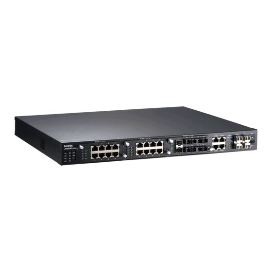
Page 11: Panel Layout
Dimension JetNet 5628G/5828G Industrial Modular Managed Ethernet Switch dimension (W x H x D) 44mm(H) x 431mm (W) x 376mm (D) Panel Layout The front panel includes 3 modular slots for Fast Ethernet Module. 4 On-Board Gigabit Combo Port which support 10/100/1000 Copper and Gigabit SFP. - Page 12 Green/Green Blinking Note: Port 25-28 is gigabit combo port, there is no LED on the rear panel. Dimension JetNet 5628G-R/5828G-R Industrial Modular Managed Ethernet Switch dimension (W x H x D) is 44mm(H) x 431mm (W) x 376mm (D) Panel Layout The front panel includes RS-232 console and LED information only.
-
Page 13: Wiring Power Inputs
For high power input, tighten the wire-clamp screws to prevent DC wires from being loosened is must. The pin assignment sequence of JetNet 5628G-R/5828G-R is N, L, PE for Power input 1 and PE, N, L for Power Input 2. -
Page 14: Wiring Digital Output
Note: When installed the Digital Output in your environment, remember to check the environment protection, like Surge protection of the connected device. The digital output contact of the JetNet 5628G/5828G do not provide high level Surge protection, this should be protected by connected device. -
Page 15: Mounting Fast Ethernet Module
The 3 modules allow you connect maximum 24 10/100Base-TX Copper ports or maximum 18 100Base-FX Fiber ports. As purchasing the JetNet 5628G/5828G, please confirm the media type and the port volume. Discuss the need with your customer and advise them your plan for the media ports is the consideration before purchasing the Ethernet module. -
Page 16: Wiring Fast Ethernet Ports
Wiring Fast Ethernet Ports JetNet 5628G/5828G includes maximum 24 RJ-45 Fast Ethernet ports. The fast Ethernet ports support 10Base-T and 100Base-TX, full or half duplex modes. All the fast Ethernet ports will auto-detect the signal from connected devices to negotiate the link speed and duplex mode. - Page 17 Korenix recommends using the Korenix certificated Gigabit SFP Transceiver. The web UI will show Unknown vendor type when choosing the SFP which is not certificated by Korenix. The certificated SFP transceiver includes 100Base-FX single/multi mode, 100/Gigabit BIDI/WDM, 1000Base-SX/LX single/multi mode ranger from 550m to 80KM.
-
Page 18: Wiring Gigabit Combo Ports
Laser/LED Beam. 2.10 Wiring Gigabit Combo Ports JetNet 5628G/5828G includes 4 RJ-45 Gigabit Ethernet ports. The speed of the gigabit Ethernet port supports 10Base-T, 100Base-TX and 1000Base-TX. JetNet 5628G/5828G also equips 4 gigabit SFP ports combo with gigabit Ethernet ports. - Page 19 2.1.1 Attach the brackets to the device by using the screws provided in the Rack Mount kit. 2.2.2 Mount the device in the 19’ rack by using four rack-mounting screws provided by the rack manufacturer. When installing multiple switches, mount them in the rack one below the other. It’s requested to reserve 0.5U-1U free space for multiple switches installing.
-
Page 20: Safety Warming
2.13 Safety Warming 2.2.1 The Equipment intended for installation in a Restricted Access Location. 2.2.2 The warning test is provided in user manual. Below is the information: ”For tilslutning af de ovrige ledere, se medfolgende installationsvejledning”. “Laite on liitettava suojamaadoitus-koskettimilla varustettuun pistorasiaan” „Apparatet ma tilkoples jordet stikkontakt“... -
Page 21: Preparation For Management
Please attach RS-232 DB-9 connector to your PC COM port, connect the other end to the Console port of the JetNet 5628G/5828G. If you lose the cable, please follow the console cable PIN assignment to find one. (Refer to the appendix). -
Page 22: Preparation For Web Interface
3.2.1 Web Interface Korenix web management page is developed by JAVA. It allows you to use a standard web-browser such as Microsoft Internet Explorer, or Mozila, to configure and interrogate the switch from anywhere on the network. - Page 23 Users have to directly modify the browser settings to selectively enable Java applets to use network ports. Note 2: The Web UI connection session of JetNet 5628G/5828G will be logged out automatically if you don’t give any input after 30 seconds. After logged out, you should re-login and key in correct user name and password again.
-
Page 24: Preparation For Telnet Console
3.3.1 Telnet Korenix JetNet 5628G/5828G supports Telnet console. You can connect to the switch by Telnet and the command lines are the same as what you see by RS232 console port. Below are the steps to open Telnet connection to the switch. - Page 25 The copyright of PuTTY Open SSH Client/PuTTY 1. In the Session configuration, enter the Host Name (IP Address of your JetNet 5628G/5828G) and Port number (default = 22). Choose the “SSH” protocol. Then click on “Open” to start the SSH session console. 2.
- Page 26 3. After few seconds, the SSH connection to JetNet 5628G/5828G is opened. You can see the login screen as the below figure. 4. Type the Login Name and its Password. The default Login Name and Password are admin / admin.
-
Page 27: Feature Configuration
Then you can remotely connect to its embedded HTML web pages or Telnet console. Korenix web management page is developed by JAVA. It allows you to use a standard web-browser such as Microsoft Internet Explorer, or Mozila, to configure and interrogate the switch from anywhere on the network. -
Page 28: Command Line Interface Introduction
Command Line Interface Introduction The Command Line Interface (CLI) is the user interface to the switch’s embedded software system. You can view the system information, show the status, configure the switch and receive a response back from the system by keying in a command. There are some different command modes. - Page 29 Global Configuration Mode: Press configure terminal in privileged EXEC mode. You can then enter global configuration mode. In global configuration mode, you can configure all the features that the system provides you. Type interface IFNAME/VLAN to enter interface configuration mode, exit to leave. ? to see the command list.
- Page 30 Available command lists of the global configuration mode. Switch(config)# interface fa1 Switch(config-if)# acceptable Configure 802.1Q acceptable frame types of a port. auto-negotiation Enable auto-negotiation state of a given port description Interface specific description duplex Specify duplex mode of operation for a port End current mode and change to enable mode exit Exit current mode and down to previous mode...
- Page 31 Summary of the 5 command modes. Command Main Function Enter and Exit Method Prompt Mode User EXEC This is the first level of access. Enter: Login successfully Switch> User can ping, telnet remote Exit: exit to logout. device, and show some basic Next mode: Type enable to information enter privileged EXEC mode.
- Page 32 Ctrl+Z To exit configuration mode. Alert message when multiple users want to configure the switch. If the administrator is in configuration mode, then the Web users can’t change the settings. JetNet 5628G/5828G allows only one administrator to configure the switch at a time.
-
Page 33: Basic Setting (Y2011, 0604)
Basic Setting (Y2011, 0604) The Basic Setting group provides you to configure switch information, IP address, User name/Password of the system. It also allows you to do firmware upgrade, backup and restore configuration, reload factory default, and reboot the system. Following commands are included in this group: 4.2.1 Switch Setting 4.2.2 Admin Password... - Page 34 MIB in MIB browser. (Note: When you attempt to view private MIB, you should compile private MIB files into your MIB browser first.) System Description: JetNet 5628G/5828G Industrial Managed Switch is the name of this product. Firmware Version: Display the firmware version installed in this device.
- Page 35 4.2.3 IP Configuration This function allows users to configure the switch’s IP address settings in JetNet 5628G Series. The JetNet 5828G series is a layer 3 switch, the IP address should be bind with VLAN interface, please go to “Routing -> IP -> IP Interface Configuration”.
- Page 36 An example of an IPv6 address is: 2001:0db8:85a3:0000:0000:8a2e:0370:7334. The default IP address of JetNet Managed Switch is fe80:0:0:0:212:77ff:fe60:ca90, and the Leading zeroes in a group may be omitted. Thus, the example address may be written as: fe80::212:77ff:fe60:ca90. IPv6 Address field: typing new IPv6 address in this field. Prefix:the size of subnet or netwok, and it equivalent to the subnetmask, but writtenin different.The default subnet mask length is 64bits, and writen in decimal value -64.
- Page 37 *Note: Please enable one synchronization protocol (PTP/NTP) only. The JetNet 5628G/5828G series also provides Daylight Saving function for some territories use.
- Page 38 Manual Setting: User can select “Manual setting” to change time as user wants. User also can click the button “Get Time from PC” to get PC’s time setting for switch. NTP client: Select the Time Setting Source to NTP client can let device enable the NTP client service.
- Page 39 Time-zone: Select the time zone where the switch is located. Following table lists the time zones for different locations for your reference. The default time zone is GMT Greenwich Mean Time. Switch(config)# clock timezone 01 (GMT-12:00) Eniwetok, Kwajalein 02 (GMT-11:00) Midway Island, Samoa 03 (GMT-10:00) Hawaii 04 (GMT-09:00) Alaska 05 (GMT-08:00) Pacific Time (US &...
- Page 40 51 (GMT+06:00) Astana, Dhaka 52 (GMT+06:00) Sri Jayawardenepura 53 (GMT+06:30) Rangoon 54 (GMT+07:00) Bangkok, Hanoi, Jakarta 55 (GMT+07:00) Krasnoyarsk 56 (GMT+08:00) Beijing, Chongqing, Hong Kong, Urumqi 57 (GMT+08:00) Irkutsk, Ulaan Bataar 58 (GMT+08:00) Kuala Lumpur, Singapore 59 (GMT+08:00) Perth 60 (GMT+08:00) Taipei 61 (GMT+09:00) Osaka, Sapporo, Tokyo 62 (GMT+09:00) Seoul 63 (GMT+09:00) Yakutsk...
- Page 41 Once you finish your configuration, click on Apply to apply your configuration. 4.2.6 DHCP Server You can select to Enable or Disable DHCP Server function. JetNet 5628G/5828G will assign a new IP address to link partners. New Pool Name: Type a name for DHCP Server Pool, then press “Apply”.
- Page 42 Add or remove an IP address from the Excluded Address List by clicking Add or Remove. Manual Binding: JetNet 5628G/5828G provides a MAC address and IP address binding and removing function. You can type in the specified IP and MAC address, then click Add to add a new MAC&IP address binding rule for a specified link partner, like PLC or any...
- Page 43 Port and IP Address: JetNet 5628G/5828G provides a Port and IP address binding and removing function. You can type in the specified Port and IP address, then click Add to add a new Port/IP address binding.To remove from the binding list, just select the rule to remove and click Remove.
-
Page 44: Dhcp Relay Agent
Leased Entries DHCP Leased Entries: JetNet 5628G/5828G provides an assigned IP address list for user check. It will show the MAC and IP address that was assigned by JetNet 5628G. In JetNet 5628G Series, there is only one IP pool available. - Page 45 DHCP Request packet. Helper Address: Type the IP address of the target DHCP Server. There are 4 available IP addresses. DHCP Option82 Relay Agent: You can specify the Circuit ID and Remote ID for DHCP Relay Agent, the DHCP server will assign IP address according to this value in the Option82 field.
- Page 46 There are 2 modes for users to backup/restore the configuration file, Local File mode and TFTP Server mode. Local File mode: In this mode, the switch acts as the file server. Users can browse the target folder and then type the file name to backup the configuration. Users can also browse the target folder and select existed configuration file to restore the configuration back to the switch.
- Page 47 4.2.8 Firmware Upgrade In this section, you can update the latest firmware for your switch. Korenix provides the latest firmware in Korenix Web site. The new firmware may include new features, bug fixes or other software changes. We’ll also provide the release notes for the update as well. For technical viewpoint, we suggest you use the latest firmware before installing the switch to the customer site.
- Page 48 new firmware. Please remind the attached users before you do this. Figure 4.2.5.1 Main UI of Firmware Upgrade There are 2 modes for users to backup/restore the configuration file, Local File mode and TFTP Server mode. Local File mode: In this mode, the switch acts as the file server. Users can browse the target folder and then type the file name to backup the configuration.
- Page 49 Figure 4.2.6.3 Error Message due to the file error or not a firmware for the switch. Before upgrading firmware, please check the file name and switch model name first and carefully. Korenix switch provide protection when upgrading incorrect firmware file, the system would not crash even download the incorrect firmware. Even we have the protection, we still ask you don’t try/test upgrade incorrect firmware, the unexpected event...
- Page 50 the firmware in the flash. The CLI show …… until the process is finished. 4.2.9 Factory Default In this section, you can reset all the configurations of the switch to default setting. Click on Reset the system will then reset all configurations to default setting. The system will show you popup message window after finishing this command.
- Page 51 Switch(config)# hostname System Name WORD Network name of this system Switch(config)# hostname JN5628G/5828G SWITCH(config)# SWITCH(config)# snmp-server location Taipei System Location SWITCH(config)# snmp-server contact korecare@korenix.com System Contact SWITCH# show snmp-server name Display SWITCH SWITCH# show snmp-server location Taipei SWITCH# show snmp-server contact korecare@korenix.com...
- Page 52 0.31-20061218 Switch# show hardware mac MAC Address : 00:12:77:FF:01:B0 Admin Password SWITCH(config)# administrator User Name and NAME Administrator account name Password SWITCH(config)# administrator orwell PASSWORD Administrator account password SWITCH(config)# administrator orwell orwell Change administrator account orwell and password orwell success. SWITCH# show administrator Display Administrator account information...
- Page 53 Jumbo Frame Switch(config)# system mtu jumbo Jumbo Frame <1500-9216> Switch(config)# system mtu jumbo 9000 DHCP Server – JetNet 5628G Series (Go to next topic for JetNet 5828G) Switch(config)# router dhcp DHCP Commands Switch(config-dhcp)# default-router DHCP Default Router Exit current mode and down to previous enable mode...
- Page 54 <cr> Switch(config-dhcp)# network DHCP Server IP Pool A.B.C.D/M network/mask ex. 10.10.1.0/24 (Network/Mask) Switch(config-dhcp)# network 192.168.10.0/24 Switch(config-dhcp)# default-router DHCP Server – A.B.C.D address Default Gateway Switch(config-dhcp)# default-router 192.168.10.254 Switch(config-dhcp)# lease DHCP Server – lease TIME second time Switch(config-dhcp)# lease 1000 (1000 second) Switch(config-dhcp)# ip dhcp excluded-address DHCP Server –...
- Page 55 A.B.C.D Helper Address Switch(config-dhcp)# ip dhcp helper-address 192.168.10.200 Switch(config-dhcp)# ip dhcp relay information option circuit-id DHCP Relay – string String Input Option82 Circuit-ID Hexadecimal Input default Defalut value (VlanID/ModuleID/Port) Switch(config-dhcp)# ip dhcp relay information option circuit-id string mycid001 <cr> Switch(config-dhcp)# ip dhcp relay information option circuit-id hex 00:01:00:03 <cr>...
- Page 56 Circuit-ID: vlan-id/module-id/port () Remote-ID: 0:12:77:ff:22:33 (001277ff2233) DHCP Server – JetNet 5828G Series The JetNet 5828G allows Multiple IP DHCP pool, the command is different than JetNet 5628G Series. See the blue wording in below. Switch# configure terminal DHCP Service Switch(config)# service dhcp ->...
- Page 57 192.168.10.99 Switch(config-dhcp)# ip dhcp relay information DHCP Relay – option Option82 Enable DHCP Relay policy Option82 Switch(config-dhcp)# ip dhcp relay information option Switch(config-dhcp)# ip dhcp relay information policy DHCP Relay – DHCP drop Relay Policy policy keep Drop/Keep/Replace option82 field replace Switch(config-dhcp)# ip dhcp relay information policy drop <cr>...
- Page 58 is name of the configuration file. Your environment may use different IP addresses or different file name. Please type target TFTP server IP or file name in this command. Switch# copy tftp: 192.168.10.33/default.conf startup-config Restore Configuration Show Startup Switch# show startup-config Configuration Show Running Switch# show running-config...
-
Page 59: Port Configuration
Port Configuration Port Configuration group enables you to enable/disable port state, or configure port auto-negotiation, speed, and duplex, flow control, rate limit control and port aggregation settings. It also allows you to view port status and aggregation information. Following commands are included in this group: 4.3.1 Understand the port mapping 4.3.2 Port Control 4.3.3 Port Status... - Page 60 Figure 4.3.2.1 The main Web UI of the Port Configuration . Select the port you want to configure and make changes to the port. In State column, you can enable or disable the state of this port. Once you disable, the port stop to link to the other end and stop to forward any traffic.
- Page 61 4.3.3 Port Status Port Status shows you current port status. Figure 4.3.3.1 shows you the port status of the Fast Ethernet Ports. The blank area (port 1-8) means the module 1 are not inserted. Due to the design limitation, the Port Status fields can not display the SFP Vendor, Wavelength and Distance of the Fast Ethernet Fiber modules.
- Page 62 The JetNet 5628G/5828G Gigabit SFP ports can read the Korenix DDM SFP information. The other vendors’ DDM SFP which is not formally certificated by Korenix can’t be read. The current JetNet 5628G/5828G UI can display the operating temperature, Tx Power and Rx Power of the SFP transceivers plugged in.
- Page 63 4.3.4 Rate Control Rate limiting is a form of flow control used to enforce a strict bandwidth limit at a port. You can program separate transmit (Egress Rule) and receive (Ingress Rule) rate limits at each port, and even apply the limit to certain packet types as described below. Figure 4.3.4.1 shows you the Limit Rate of Ingress and Egress.
- Page 64 The aggregated ports can interconnect to the other switch which also supports Port Trunking. Korenix Supports 2 types of port trunking. One is Static Trunk, the other is 802.3ad. When the other end uses 802.3ad LACP, you should assign 802.3ad LACP to the trunk.
- Page 65 Trunk Size: The switch can support up to 8 trunk groups. Each trunk group can support up to 8 member ports. Since the member ports should use same speed/duplex, max groups for 100M ports would be 7, and 3 for gigabit ports. Group ID: Group ID is the ID for the port trunking group.
- Page 66 Individual: When LACP is enabled, member ports of LACP group which are not connected to correct LACP member ports will be displayed in the Individual column. Link Down: When LACP is enabled, member ports of LACP group which are not linked up will be displayed in the Link Down column.
- Page 67 Switch(config-if)# flowcontrol off Flowcontrol off for port 1 set ok! Port Status Switch# show interface fa1 Port Status Interface fastethernet1 Administrative Status : Enable Operating Status : Connected Duplex : Full Speed : 100 MTU: 1518 Flow Control :off Default Port VLAN ID: 1 Ingress Filtering : Disabled Acceptable Frame Type : All Port Security : Disabled...
- Page 68 Rate Control Switch(config-if)# rate-limit Rate Control – egress Outgoing packets Ingress or Egress ingress Incoming packets Note: To enable rate control, you should select the Ingress or Egress rule first; then assign the packet type and bandwidth. Switch(config-if)# rate-limit ingress bandwidth Rate Control - <0-100>...
- Page 69 Select the load balance type and “Enter”. SWITCH(config-if)# lacp LACP – Port Setting port-priority LACP priority for physical interfaces timeout assigns an administrative LACP timeout SWITCH(config-if)# lacp port-priority <1-65535> Valid port priority range 1 - 65535 (default is 32768) SWITCH(config-if)# lacp timeout Long/Short Timeout long specifies a long timeout value (default)
-
Page 70: Network Redundancy
MultiRing Technology. The Ring ports can be LACP/Port Trunking ports, after aggregated ports to a group, the group of ports can act as the Ring port of the Ring. This is Korenix Pattened TrunkRing Technology. Advanced Rapid Dual Homing(RDH) technology also facilitates JetNet switch to connect with a core managed switch easily and conveniently. - Page 71 4.4.1 STP Configuration This page allows select the STP mode and configuring the global STP/RSTP Bridge Configuration. The STP mode includes the STP, RSTP, MSTP and Disable. Please select the STP mode for your system first. The default mode is RSTP enabled. After select the STP or RSTP mode, continue to configure the global Bridge parameters for STP and RSTP.
- Page 72 Since different RSTP aware switches may have their own mechanism to calculate the message age. So that this is most possibly occurred when interoperate different vendors’ RSTP aware switches together. The maximum volume of the Korenix RSTP domain is 23, configure the MAX Age lower than 23 is recommended.
- Page 73 Some of the rapid state transitions that are possible within RSTP depend upon whether the port of concern can only be connected to another bridge (i.e. it is served by a point-to-point LAN segment), or if it can be connected to two or more bridges (i.e. it is served by a shared-medium LAN segment).
- Page 74 4.4.3 RSTP Info This page allows you to see the information of the root switch and port status. Root Information: You can see root Bridge ID, Root Priority, Root Port, Root Path Cost and the Max Age, Hello Time and Forward Delay of BPDU sent from the root switch. Port Information: You can see port Role, Port State, Path Cost, Port Priority, Oper P2P mode, Oper edge port mode and Aggregated(ID/Type).
- Page 75 The figure shows there are 2 VLANs/MSTP Instances and each instance has its Root and forwarding paths. A Common Spanning Tree (CST) interconnects all adjuacent MST regions and acts as a virtual bridge node for communications with STP or RSTP nodes in the global network. MSTP connects all bridges and LAN segments with a single Common and Internal Spanning Tree (CIST).
- Page 76 After enabled MSTP mode, then you can go to the MSTP Configuraiton pages. MSTP Region Configuration This page allows configure the Region Name and its Revision, mapping the VLAN to Instance and check current MST Instance configuration. The network can be divided virtually to different Regions.
- Page 77 Instance ID: Select the Instance ID, the available number is 1-15. VLAN Group: Type the VLAN ID you want mapping to the instance. Instance Priority: Assign the priority to the instance. After finish your configuration, click on Add to apply your settings. Current MST Instance Configuration This page allows you to see the current MST Instance Configuration you added.
- Page 78 Path Cost: Enter a number between 1 and 200,000,000. This value represents the “cost” of the path to the other bridge from the transmitting bridge at the specified port. Priority: Enter a value between 0 and 240, using multiples of 16. This is the value that decides which port should be blocked by priority in a LAN.
- Page 79 Multiple Super Ring (MSR) technology is Korenix’s 3 generation Ring redundancy technology. This is patented and protected by Korenix and is used in countries all over the world. MSR ranks the fastest restore and failover time in the world, 0 ms for restore and about milliseconds level for failover for 100Base-TX copper port.
- Page 80 Ring ID. The maximum Ring number one switch can support is half of total port volume. For example, the JetNet 5628G is a 24 Fast Ethernet + 4 Gigabit port design, that means maximum 14 Rings (12 x 100M Rings and 2 Gigabit Rings) can be aggregated to one JetNet 5628G.
- Page 81 Ring Port2: Assign another port for ring connection Path Cost: Change the Path Cost of Ring Port2 Rapid Dual Homing: Rapid Dual Homing is an important feature of Korenix 3 generation Ring redundancy technology. When you want to connect multiple RSR or form redundant topology with other vendors,RDH could allow you to have maximum 7 multiple links for redundancy without any problem.
- Page 82 Create multiple ring ID and assign different ring port 1 and port 2 to each ring, thus the switch can have multiple rings in one JetNet 5628G. When implementing MultiRing, remember that the different rings can NOT use the same ring ID.
- Page 83 Role state Transition Count: This number means how many times the Ring status has been transformed between Normal and Abnormal state. 4.4.9 Command Lines: Feature Command Line Global (STP, RSTP, MSTP) Enable Switch(config)# spanning-tree enable Disable Switch (config)# spanning-tree disable Mode (Choose the Switch(config)# spanning-tree mode Spanning Tree mode)
- Page 84 Switch(config-mst)# name NAME the name string Switch(config-mst)# name korenix Region Revision: Switch(config-mst)# revision <0-65535> the value of revision Switch(config-mst)# revision 65535 Mapping Instance to Switch(config-mst)# instance VLAN (Ex: Mapping <1-15> target instance number VLAN 2 to Instance 1) Switch(config-mst)# instance 1 vlan VLANMAP target vlan number(ex.10) or range(ex.1-10)
- Page 85 not applied. Revision 65535 Instance Vlans Mapped -------- -------------------------------------- 1,4-4094 (-> The instance is not applied after Abort settings.) ------------------------------------------------ Config HMAC-MD5 Digest: 0xB41829F9030A054FB74EF7A8587FF58D ------------------------------------------------ RSTP System RSTP Setting The mode should be rst, the timings can be configured in global settings listed in above.
- Page 86 MSTP Information MSTP Configuraiton Switch# show spanning-tree mst configuration Current MST configuration (MSTP is Running) Name [korenix] Revision 65535 Instance Vlans Mapped -------- -------------------------------------- 1,4-4094 ------------------------------------------------ Config HMAC-MD5 Digest: 0xB41829F9030A054FB74EF7A8587FF58D ------------------------------------------------ Display all MST Switch# show spanning-tree mst Information ###### MST00...
- Page 87 mapped -------- ---------- ---------- -------- ---------- --------------------- Designated Forwarding 200000 128.1 1,4-4094 Designated Forwarding 200000 128.1 Designated Forwarding 200000 128.1 Multiple Super Ring Create or configure a Switch(config)# multiple-super-ring 1 Ring Ring 1 created Switch(config-multiple-super-ring)# Note: 1 is the target Ring ID which is going to be created or configured.
- Page 88 Ring Port : fa1, fa2 Path Cost : 100, 200 Dual-Homing II : Disabled Statistics : Watchdog sent 0, received 0, missed Link Up sent 0, received Link Down sent 0, received Role Transition count 0 Ring State Transition count 1 Ring ID is optional.
-
Page 89: Vlan
Layer 2 switch, without actually disconnecting these devices from their original switches. JetNet 5628G/5828G Series Industrial Ethernet Switch supports 802.1Q VLAN. 802.1Q VLAN is also known as Tag-Based VLAN. This Tag-Based VLAN allows VLAN to be created across different switches (see Figure 1). - Page 90 VLAN Configuration group enables you to Add/Remove VLAN, configure port Ingress/Egress parameters and view VLAN table. Following commands are included in this group: 4.5.1 VLAN Port Configuration 4.5.2 VLAN Configuration 4.5.3 GVRP Configuration 4.5.4 VLAN Table 4.5.5 CLI Commands of the VLAN 4.5.1 VLAN Port Configuration VLAN Port Configuration allows you to set up VLAN port parameters to specific port.
- Page 91 Tunnel Mode: This is the new command for QinQ. The command includes None, 802.1Q Tunnel and 802.1Q Tunnel Uplink. The figure shows the relationship between 802.1Q Tunnel and 802.1Q Tunnel Uplink. Following is the modes you can select. None: Remian VLAN setting, no QinQ. 802.1Q Tunnel: The QinQ command applied to the ports which connect to the C-VLAN.
- Page 92 VLAN can access the switch. The default management VLAN ID is 1. Note: The management VLAN is only applied to JetNet 5628G Series. Go to “Routing -> IP -> IP Configuration” to configure management IP address for JetNet 5828G Series.
- Page 93 Static VLAN Configuration You can see the created VLANs and specify the egress (outgoing) port rule to be Untagged or Tagged here. Figure 4.5.2.3 Static VLAN Configuration table. You can see that new VLAN 3 is created. VLAN name is test. Egress rules of the ports are not configured now. Figure 4.5.2.4 Configure Egress rule of the ports.
- Page 94 reduce the configuration effort. For high volume and high secure request network, the Static VLAN configuration is always preferred. GVRP Protocol: Allow user to enable/disable GVRP globally. State: After enable GVRP globally, here still can enable/disable GVRP by port. Join Timer: Controls the interval of sending the GVRP Join BPDU. An instance of this timer is required on a per-Port, per-GARP Participant basis Leave Timer: Control the time to release the GVRP reservation after received the GVRP Leave BPDU.
- Page 95 After created the VLAN, the status of this VLAN will remain in Unused status until you add ports to the VLAN. 4.5.5 CLI Commands of the VLAN Command Lines of the VLAN port configuration, VLAN configuration and VLAN table display Feature Command Line VLAN Port Configuration(Go to the port interface configuration mode first.)
- Page 96 Egress rule – Untagged Switch(config-if)# switchport access vlan 2 (for VLAN 2) switchport access vlan - success Egress rule – Tagged Switch(config-if)# switchport trunk allowed vlan add 2 (for VLAN 2) Display – Port Ingress Switch# show interface fa1 Rule (PVID, Ingress Interface fastethernet1 Filtering, Acceptable Administrative Status : Enable...
- Page 97 interface fastethernet6 switchport access vlan add 1-2 switchport trunk allowed vlan add 10 switchport dot1q-tunnel mode uplink VLAN Configuration Create VLAN (2) Switch(config)# vlan 2 vlan 2 success Switch(config)# interface vlan 2 Switch(config-if)# Note: In CLI configuration, you should create a VLAN interface first.
- Page 98 inet 192.168.10.100/24 broadcast 192.168.10.255 input packets 639, bytes 38248, dropped 0, multicast packets 0 input errors 0, length 0, overrun 0, CRC 0, frame 0, fifo 0, missed 0 output packets 959, bytes 829280, dropped 0 output errors 0, aborted 0, carrier 0, fifo 0, heartbeat 0, window 0 collisions 0 GVRP configuration GVRP enable/disable...
-
Page 99: Private Vlan
Private VLAN The private VLAN helps to resolve the primary VLAN ID shortage, client ports’ isolation and network security issues. The Private VLAN provides primary and secondary VLAN within a single switch. Primary VLAN: The uplink port is usually the primary VLAN. A primary VLAN contains promiscuous ports that can communicate with lower Secondary VLANs. - Page 100 communicate with each other. 4.6.2 PVLAN Port Configuration PVLAN Port Configuration page allows configure Port Configuration and Private VLAN Association. Private VLAN Association Secondary VLAN: After the Isolated and Community VLAN Type is assigned in Private VLAN Configuration page, the VLANs are belonged to the Secondary VLAN and displayed here.
- Page 101 For example: 1. VLAN Create: VLAN 2-5 are created in VLAN Configuration page. 2. Private VLAN Type: VLAN 2-5 has its Private VLAN Type configured in Private VLAN Configuration page. VLAN 2 is belonged to Primary VLAN. VLAN 3-5 are belonged to secondary VLAN (Isolated or Community). 3.
- Page 102 4.6.3 Private VLAN Information This page allows you to see the Private VLAN information. 4.6.4 CLI Command of the PVLAN Command Lines of the Private VLAN configuration Feature Command Line Private VLAN Configuration Create VLAN Switch(config)# vlan 2 vlan 2 success Switch(config-vlan)# End current mode and change to enable mode exit...
- Page 103 Primary Type Switch(config-vlan)# private-vlan primary <cr> Isolated Type Switch(config-vlan)# private-vlan isolated <cr> Community Type Switch(config-vlan)# private-vlan community <cr> Private VLAN Port Configuraiton Go to the port Switch(config)# interface (port_number, ex: gi9) configuraiton Switch(config-if)# switchport private-vlan host-association Set the private VLAN host association mapping map primary VLAN to secondary VLAN Private VLAN Port Type...
- Page 104 Vlan Type Ports ---- ----------------- ----------------- primary gi10 isolated community community fa7,gi9 primary Host List Switch# show vlan private-vlan port-list Ports Mode Vlan ----- ----------- ---- normal normal normal normal normal normal host host host promiscuous 2 Running Config Switch# show run Information Building configuration...
- Page 105 switchport trunk native vlan 5 switchport mode private-vlan host switchport private-vlan host-association 2 3 interface gigabitethernet10 switchport access vlan add 2,5 switchport trunk native vlan 2 switchport mode private-vlan promiscuous switchport private-vlan mapping 2 add 3-5 ……… ……..
-
Page 106: Traffic Prioritization
Traffic Prioritization Quality of Service (QoS) provides traffic prioritization mechanism which allows users to deliver better service to certain flows. QoS can also help to alleviate congestion problems and ensure high-priority traffic is delivered first. This section allows you to configure Traffic Prioritization settings for each port with regard to setting priorities. - Page 107 In JetNet, users can freely assign the mapping table or follow the suggestion of the 802.1p standard. Korenix uses 802.p suggestion as default values. You can find CoS values 1 and 2 are mapped to physical Queue 0, the lowest queue. CoS values 0 and 3 are mapped to physical Queue 1, the low/normal physical queue.
- Page 108 4.7.3 DSCP-Queue Mapping This page is to change DSCP values to Physical Queue mapping table. Since the switch fabric of JetNet only supports 4 physical queues, Lowest, Low, Middle and High. Users should therefore assign how to map DSCP value to the level of the physical queue. In JetNet, users can freely change the mapping table to follow the upper layer 3 switch or routers’...
- Page 109 Switch(config)# qos queue-sched wrr 1 2 3 4 5 6 7 8 The queue scheduling scheme is setting to Weighted Round Robin. Assign the ratio for the 8 classes of service. Port Setting – CoS Switch(config)# interface fa1 (Default Port Priority) Switch(config-if)# qos priority DEFAULT-PRIORITY Assign an priority (7 highest) Switch(config-if)# qos priority 7...
- Page 110 Note: Format: qos cos-map priority_value queue_value Map CoS 0 to Queue 1 Switch(config)# qos cos-map 0 1 The CoS to queue mapping is set ok. Map CoS 1 to Queue 0 Switch(config)# qos cos-map 1 0 The CoS to queue mapping is set ok. Map CoS 2 to Queue 0 Switch(config)# qos cos-map 2 0 The CoS to queue mapping is set ok.
-
Page 111: Multicast Filtering
Multicast Filtering For multicast filtering, JetNet 5628G/5828G uses IGMP Snooping technology. IGMP (Internet Group Management Protocol) is an Internet Protocol that provides a way for internet device to report its multicast group membership to adjacent routers. Multicasting allows one computer on the internet to send data to a multitude of other computers that have identified themselves as being interested in receiving the originating computers data. - Page 112 4.8.2 IGMP Query In JetNet 5628G Series, there is only one IGMP Query, it is applied to management VLAN. In JetNet 5828G Series, there are multiple IP/VLAN interfaces for layer 3 routing. Each IP/VLAN interface can act as the IGMP Query for its own VLAN. Each IP/VLAN interface should have its own IGMP Query.
- Page 113 This is the figure of JetNet 5828G Series. IGMP Query can be applied to each IP/VLAN interface. Select the Version of each VLAN ID and then “Apply” the setting. Note that only the IGMP Query can only be enabled in active VLAN/IP interface. You should create VLAN and assign IP address to the VLAN interface first.
- Page 114 Send to Query Port: The unknown Multicast traffic can be directed to the Query port. The Query port means the port learnt the IGMP Query. This is usually the uplink ports to other switches. Send to All Ports: The unknown Multicast traffic will be flooded to all the ports. Discard: If the Discard is selected, all the unknown multicast data will be discarded.
- Page 115 all existed vlan Switch(config)# ip igmp snooping vlan 1-2 IGMP snooping is enabled on VLAN 1-2. Disable IGMP Snooping Switch(config)# no ip igmp snoopin - Global IGMP snooping is disabled globally ok. Disable IGMP Snooping Switch(config)# no ip igmp snooping vlan 3 - VLAN IGMP snooping is disabled on VLAN 3.
- Page 116 interface vlan1 ip address 192.168.10.43/24 no shutdown ip igmp interface vlan2 ip address 192.168.2.254/24 no shutdown ip igmp interface vlan3 ip address 192.168.3.254/23 no shutdown! ……. ip routing qos queue-sched rr spanning-tree mst configuration exit ip igmp snooping ip igmp snooping vlan 1 ip igmp snooping vlan 2 ip igmp snooping vlan 3 ……….
-
Page 117: Routing
Routing Layer 3 Routing Feature is the most important feature of the the Layer 3 Modular Managed Ethernet Switch. Since the hosts located in different broadcast domain can’t communicate by themselves, once there is a need to communicate among the different VLANs, the layer 3 routing feature is requested. - Page 118 Age Time (secs): This is the Age time setting of the ARP entry. Once there is no packet (IP+MAC) hit the entry within the time, the entry will be aged out. Short ARP age time leads the entry aged out easier and re-learn often, the re-learn progress lead the communication stop.
- Page 119 Routing Mode: This command allows user to Enable or Disable the global IP Routing mode. After Enabled, the switch can route traffic. If it is Disabled, the switch acts as a pure layer 2 switch, all the traffic can NOT be routed. All the network settings of routing protocols will be disabled and deleted.
- Page 120 Interface: The name of the VLAN. Status: After enabled the routing state, the Status shows “Up”. After disabled the routing state, the status shows “Down”. State: Enable or Disable the IP Routing Interface state. After disabled, the interface just work as a layer 2 VLAN. After enabled, the interface can support IP routing feature. IP Address: Assign the IP Address for the target VLAN.
- Page 121 Static Route: A static route entry to and from a stub network to another stub network. The static route is usually configured to connect the neighbor router/switch, the both routers/switches then can communicate through the route. While configuring Static Route, all the fields in Route entry like the destination network and its netmask, the valid route interface to the destination and distance are needed to be specified.
- Page 122 The system maintains the routing table information and updates it once the routing interfaces changed. The routing table information is important to find out the possible and best route in the field especially when troubleshooting the network problem. The definition of the fields is listed in below: Routing Protocol: The field shows the entry is a local interface or learnt from the routing protocol.
- Page 123 RIP Configuration This page shows how to configure RIP protocol. RIP Protocol: Choose the RIP Version 1 or Version 2 or Disable RIP protocol in here. Routing for Networks: All the networks no matter directly connected or learnt from other router/switch should be added to the switch.
- Page 124 4.9.5 OSPF The OSPF is short of the Open Shortest Path First. OSPF is a link-state protocol. The Link is an interface on the router, it equips the IP, mask, the type of network, the routers connected to that network. The State is its relationship to its neighboring routers.
- Page 125 address or ID. All the network address should be added. Select the Network Address, then you can “Remove” the setting. Click “Reload” to reload the new entry. 4.9.5.2 OSPF Interface Configuration This page allows user to see the OSPF network address and the parameters of each interface.
- Page 126 Interface: The VLAN Interface name. Area: The area ID of the Interface you added. The Area ID must be the same for all routers/switches on a network. Cost: The distance of this link/Interface, the default is identified depends on what the bandwidth is by the system.
- Page 127 State: Down- initial state of the neighbor conversation - no recent information has been received from the neighbor. Attempt - no recent information has been received from the neighbor but a more concerted effort should be made to contact the neighbor. Init - an Hello packet has recently been seen from the neighbor, but bi-directional communication has not yet been established.
- Page 128 Once you finish configuring the settings, click on Apply or Add to apply your configuration.
- Page 129 DVMRP and PIM/DM. Another is Spars mode, like the PIM/SM. In JetNet 5828G first firmware release, it only supports the DVMRP protocol. The PIM/DM and PIM/SM will be supported in later firmware. Please check Korenix News and Web site for future update.
- Page 130 MRoute configuration. Click “Add” to add it. Then the entry is displayed in the local MRoute table. 4.9.6.2 DVMRP (Check the release version with Korecare@korenix.com) DVMRP is a Distance Vector-based Multicast Routing Protocol, it is similar to the RIP operating.
- Page 131 Path Forwarding checks to determine when multicast traffic should be forwarded to downstream interfaces. In this way, source-rooted shortest path trees can be formed to reach all group members from each source network of multicast traffic. While configuring the DVMRP routing protocol, the IP interfaces should be activated and IP routing, IGMP of the system and interfaces should be enabled.
- Page 132 DVMRP Neighbor Table The Neighbor Table is a list to keep the neighboring multicast routers on every attached network. The information can be derived by the DVMRP routing messages that are received. A neighbor that has not been heard from in NEIGHBOR_TIMEOUT seconds should be considered to be down.
- Page 133 Multicast Group: The Multicast Group IP address of the steam. Source IP: The source IP address of the stream. Interface: The interface name of the source IP. Life: The timer is decreased continuously. After the life timer is timeout, the entry will be deleted and the DVMRP probe will be generated again to add new Multicast route entry.
- Page 134 4.9.7 VRRP The VRRP represent for the Virtual Router Redundancy Protocol. To further ensure the high reliability of an environment, the JetNet Layer 3 switch supports the VRRP protocol allowing the hosts to continuously direct traffic to the default gateway without the default gateway configuration change.
- Page 135 Virtual ID: This is a virtual ID range from 1~255. The switches within the same VRRP domain should have the same Virtual ID. Virtual IP: This is the virtual IP of the VRRP domain. This is the Gateway IP of the clients. Priority: The priority of the entry of this switch.
- Page 137 4.9.8 CLI Commands of the Routing Feature Command Lines of the Routing configuration Feature Command Line Age Time Switch(config)# arp aging-time <10-21600> seconds (10-21600) Switch(config)# arp aging-time 1200 (20min for example) Static ARP Entry Switch(config)# arp A.B.C.D IP address of ARP entry aging-time Aging Time Switch(config)# arp 192.168.100.1 MACADDR 48-bit hardware address of ARP entry...
- Page 138 Interface vlan1 Change to DOWN Activate the IP Interface Switch(config-if)# no shutdown arping for the MAC arp: SIOCDARP(pub): No such file or directory ARPING to 192.168.10.254 from 192.168.10.43 via vlan1 Sent 3 probe(s) (3 broadcast(s)) Received 0 reply (0 request(s), 0 broadcast(s)) Interface vlan1 Change to UP Show ip routing status Switch# show ip routing...
- Page 139 C>* 192.168.2.0/24 is directly connected, vlan2 O>* 192.168.3.0/24 [110/30] via 192.168.5.254, vlan5, 00:09:31 O>* 192.168.4.0/24 [110/20] via 192.168.5.254, vlan5, 00:09:31 192.168.5.0/24 [110/10] is directly connected, vlan5, 00:09:31 C>* 192.168.5.0/24 is directly connected, vlan5 192.168.10.0/24 [110/10] is directly connected, vlan1, 00:07:15 C>* 192.168.10.0/24 is directly connected, vlan1 O>* 192.168.12.0/24 [110/40] via 192.168.5.254, vlan5, 00:09:31...
- Page 140 Switch(config-router)# passive-interface default <cr> RIP default Metric Switch(config-router)# default-metric (usually = 1) <1-16> Default metric RIP Setting Switch# show ip rip status Routing Protocol is "rip" Sending updates every 30 seconds with +/-50%, next due in 23 seconds Timeout after 180 seconds, garbage collect after 120 seconds Outgoing update filter list for all interface is not set Incoming update filter list for all interface is not set...
- Page 141 information default-metric Set metric of redistributed routes distance Define an administrative distance distribute-list Filter networks in routing updates End current mode and change to enable mode exit Exit current mode and down to previous mode list Print command list neighbor Specify neighbor router network Enable routing on an IP network...
- Page 142 OSPF Router with ID (192.168.3.254) Router Link States (Area 0.0.0.0) Link ID ADV Router Age Seq# CkSum Link count 192.168.3.253 192.168.3.253 928 0x80000009 0xf3b2 2 192.168.3.254 192.168.3.254 927 0x8000000a 0xd4aa 3 192.168.5.254 192.168.5.254 230 0x80000006 0xc248 2 Net Link States (Area 0.0.0.0) Link ID ADV Router Age Seq#...
- Page 143 Multicast Routing (Before enable MRoute/DVMRP, the IP Interfaces’ setting should be configured and activated first.) Enable the MRoute & Switch(config)# ip multicast-routing Configure the IP Networks Switch(config)# router mroute (IP Multicast Routing Switch(config-mroute)# network within one switch) A.B.C.D/M IP prefix <network>/<length>, e.g., 35.0.0.0/8 WORD Interface name Switch(config-dvmrp)# network 192.168.2.0/24...
- Page 144 The virtual router of vlan1 count is 1. Create virtual router 1 success. Priority of the interface Switch(config-if)# vrrp 1 priority <1-254> virtual router's priority value in range 1-254, 255 for virtual IP owner and 100 for backup by default Preempt of the interface Switch(config-if)# vrrp 1 preempt Set virtual router preemption mode to enabled success.
-
Page 145: Snmp
With Read and Write privilege, you have the ability to read and set the values of MIB tables. Default community string is Private. JetNet 5628G/5828G allows users to assign 4 community strings. Type the community string and select the privilege. Then press Apply. - Page 146 SNMP v3 can provide more security functions when the user performs remote management through SNMP protocol. It delivers SNMP information to the administrator with user authentication; all of data between JetNet 5628G/5828G and the administrator are encrypted to ensure secure communication.
- Page 147 This page allows users to Enable SNMP Trap, configure the SNMP Trap server IP, Community name, and trap Version V1 or V2. After configuration, you can see the change of the SNMP pre-defined standard traps and Korenix pre-defined traps. The pre-defined traps can be found in Korenix private MIB.
- Page 148 4.10.4 CLI Commands of the SNMP Command Lines of the SNMP configuration Feature Command Line SNMP Community Read Only Community Switch(config)# snmp-server community public ro community string add ok Read Write Community Switch(config)# snmp-server community private rw community string add ok SNMP Trap Enable Trap Switch(config)# snmp-server enable trap...
-
Page 149: Security
4.11 Security JetNet 5628G/5828G provides several security features for you to secure your connection. The features include Port Security and IP Security. Following commands are included in this group: 4.9.1 Filter Set (Access Control List) 4.9.2 IEEE 802.1x 4.9.3 CLI Commands of the Security 4.11.1 Filter Set (Access Control List) - Page 150 MAC Filter (Port Security): The MAC Filter allows user to define the Access Control List for specific MAC address or a group of MAC addresses. Filter ID/Name: The name for this MAC Filter entry. Action: Permit to permit traffic from specified sources. Deny to deny traffic from those sources.
- Page 151 Egress Port: Bind the MAC Filter rule to specific front port. Once you finish configuring the ACE settings, click on Add to apply your configuration. You can see below screen is shown. Example of the below Entry: Permit Source MAC “0012.7700.0000” to Destination MAC “0012.7700.0002”. The Permit rule is egress rule and it is bind to Gigabit Ethernet Port 25.
- Page 152 Example: IP Standard Access List: This kind of ACL allows user to define filter rules according to the source IP address. IP Extended Access List: This kind of ACL allows user to define filter rules according to the source IP address, destination IP address, Source TCP/UDP port, destination TCP/UDP port and ICMP type and code.
- Page 153 Filter ID/Name: The ID or the name for this IP Filter entry. Action: Permit to permit traffic from specified sources. Deny to deny traffic from those sources. Source/Destination Address: Type the source/destination IP address you want configure. Source/Destination Wildcard: This command allows user to define single host or a group of hosts based on the wildcard.
- Page 154 4.11.3 IEEE 802.1x 4.9..1 802.1X configuration IEEE 802.1X is the protocol that performing authentication to obtain access to IEEE 802 LANs. It is port-base network access control. With the function, JetNet 5628G/5828G could control which connection is available or not.
- Page 155 System AuthControl: To enable or disable the 802.1x authentication. Authentication Method: Radius is a authentication server that provide key for authentication, with this method, user must connect switch to server. If user select Local for the authentication method, switch use the local user data base which can be create in this page for authentication.
- Page 156 4.9.3.2 802.1x Port Configuration After the configuration of Radius Server or Local user list, user also need configure the authentication mode, authentication behavior, applied VLAN for each port and permitted communication. The following information will explain the port configuration. Port control: Force Authorized means this port is authorized; the data is free to in/out. Force unauthorized just opposite, the port is blocked.
- Page 157 Once you finish configuring the settings, click on Apply to apply your configuration. Click Initialize Selected to set the authorize state of selected port to initialize status. Click Reauthenticate Selected to send EAP Request to supplicant to request reauthentication. Click Default Selected to reset the configurable 802.1x parameters of selected port to the default values.
- Page 158 <1-99> Standard IP access-list number <1300-1999> Standard IP access-list number (expanded range) WORD Access-list name Switch(config)# ip access-list standard 1 Switch(config-std-acl)# deny Specify packets to reject permit Specify packets to forward End current mode and change to enable mode exit Exit current mode and down to previous mode list Print command list...
- Page 159 Any source host host A single source host Switch(config-ext-acl)#permit ip 192.168.10.1 A.B.C.D Source wildcard bits Switch(config-ext-acl)#permit ip 192.168.10.1 0.0.0.1 A.B.C.D Destination address Any destination host host A single destination host Switch(config-ext-acl)#permit ip 192.168.10.1 0.0.0.1 192.168.10.100 0.0.0.1 [IFNAME] Egress interface name Switch(config-ext-acl)#permit ip 192.168.10.1 0.0.0.1 192.168.10.100 0.0.0.1 gi26 Note: Follow the below rule to configure ip extended access list.
- Page 160 RADIUS Accounting Port number NOT given. (default=1813) Secondary RADIUS Server IP : 192.168.10.250 Secondary RADIUS Server Key : 5678 Secondary RADIUS Server Port : 1812 Secondary RADIUS Accounting Port : 1813 User name/password Switch(config)# dot1x username korenix passwd korenix vlan for authentication...
-
Page 161: Warning
4.12 Warning JetNet 5628G/5828G provides several types of Warning features for you to remote monitor the status of end devices or the change of your network. The features include Fault Relay, System Log and SMTP E-mail Alert. Following commands are included in this group: 4.10.1 Fault Relay... - Page 162 DI State: High or Low. Select the power voltage you want to monitor. How to configure: Select the DI Number you want to monitor and DI State, High or Low. For example: When DI 1 and High are selected, it means when DI 1 is pulled high, the system will short Relay Output and light DO LED.
- Page 163 Event Type: Power Failure Power ID: Select Power AC1, Power AC2, Power DC 1, Power DC2 or Any you want to monitor. When the power you selected is shut down or broken, the system will short Relay Out and light the DO LED. Event Type: Like Failure Link: Select the port ID you want to monitor.
- Page 164 How to configure: After selecting Ping Failure event type, the system will turn Relay Output to short state and continuously ping the target device. When the ping failure occurred, the switch will turn the Relay Output to open state for a period of Reset Time. After the Reset Time timeout, the system will turn the Relay Output to close state.
- Page 165 There are 2 System Log modes provided by JetNet 5628G/5828G, local mode and remote mode. Local Mode: In this mode, JetNet 5628G/5828G will print the occurred events selected in the Event Selection page to System Log table of JetNet 5628G/5828G. You can monitor the system logs in [Monitor and Diag] / [Event Log] page.
- Page 166 Diag] / [Event Log] page. 4.12.4 SMTP Configuration JetNet 5628G/5828G supports E-mail Warning feature. The switch will send the occurred events to remote E-mail server. The receiver can then receive notification by E-mail. The E-mail warning is conformed to SMTP standard.
- Page 167 Field Description SMTP Server IP Address Enter the IP address of the email Server Authentication Click on check box to enable password User Name Enter email Account name (Max.40 characters) Password Enter the password of the email account Confirm Password Re-type the password of the email account You can set up to 4 email addresses to receive email alarm from JetNet Rcpt E-mail Address 1...
- Page 168 <cr> reset reset a device Switch(config)# relay 1 ping 192.168.10.33 reset <1-65535> reset time Switch(config)# relay 1 ping 192.168.10.33 reset 60 <0-65535> hold time to retry Switch(config)# relay 1 ping 192.168.10.33 reset 60 60 Port Link Failure Switch(config)# relay 1 port PORTLIST port list Switch(config)# relay 1 port fa1-5 Power Failure...
- Page 169 Switch(config)# smtp-server server 192.168.10.100 admin@korenix.com SMTP Email Alert set Server: 192.168.10.100, Account: admin@korenix.com ok. Receiver mail Switch(config)# smtp-server receipt 1 korecare@korenix.com SMTP Email Alert set receipt 1: korecare@korenix.com ok. Authentication with Switch(config)# smtp-server authentication username admin username and password admin password...
-
Page 170: Monitor And Diag
4.13 Monitor and Diag JetNet 5628G/5828G provides several types of features for you to monitor the status of the switch or diagnostic for you to check the problem when encountering problems related to the switch. The features include MAC Address Table, Port Statistics, Port Mirror, Event Log and Ping. - Page 171 4.13.2 Port Statistics In this page, you can view operation statistics for each port. The statistics that can be viewed include Link Type, Link State, Rx Good, Rx Bad, Rx Abort, Tx Good, Tx Bad and Collision. Rx means the received packet while Tx means the transmitted packets. Note: If you see many Bad, Abort or Collision counts increased, that may mean your network cable is not connected well, the network performance of the port is poor…etc.
- Page 172 4.13.3 Port Mirroring Port mirroring (also called port spanning) is a tool that allows you to mirror the traffic from one or more ports onto another port, without disrupting the flow of traffic on the original port. Any traffic that goes into or out of the Source Port(s) will be duplicated at the Destination Port.
- Page 173 In the 4.10.3, we have introduced System Log feature. When System Log Local mode is selected, JetNet 5628G/5828G will record occurred events in local log table. This page shows this log table. The entry includes the index, occurred data and time and content of the events.
- Page 174 4.13.6 Ping Utility This page provides Ping Utility for users to ping remote device and check whether the device is alive or not. Type Target IP address of the target device and click on Start to start the ping. After few seconds, you can see the result in the Result field.
- Page 175 Modbus/TCP that it can be polled through Ethernet. Thus the Modbus/TCP master can read or write the Modbus registers provided by the Industrial Ethernet Switch. Korenix JetNet 5628G/5828G implement the Modbus/TCP registers into the latest firmware. The registers include the System information, firmware information, IP address, power status, interfaces’...
- Page 176 Word 0 Lo byte = ‘e’ Word 1 Hi byte = ‘T’ Word 1 Lo byte = ‘N’ Word 2 Hi byte = ‘e’ Word 2 Lo byte = ‘t’ Word 3 Hi byte = ‘5’ Word 3 Lo byte = ‘8’ Word 4 Lo byte = ‘2’...
- Page 177 Word 1 Lo byte = 0x04 Word 2 Hi byte = 0x05 Word 2 Lo byte = 0x06 0x020F to 241 words Reserved address space 0x2FF 0x0300 2 words IP address Ex: IP = 192.168.10.1 Word 0 Hi byte = 0xC0 Word 0 Lo byte = 0xA8 Word 1 Hi byte = 0x0A Word 1 Lo byte = 0x01...
- Page 178 0x0411 1 word 0x0000:Off 0x0001:On 0xFFFF: unavailable 0x0412 1 word 0x0000:Off 0x0001:On 0xFFFF: unavailable 0x0413 1 word 0x0000:Off 0x0001:On 0xFFFF: unavailable 0x0414 to 12 words Reserved address space 0x041F 0x0420 1 word 0x0000:Off 0x0001:On 0x0421 1 word 0x0000:Off 0x0001:On 0x0422 1 word 0x0000:Off 0x0001:On...
- Page 179 0x0003: auto (half) 0x0004: auto (full) 0x0005: auto 0xFFFF: unavailable 0x1260 to 1 word Speed 0x127F 0x0001: 10 0x0002: 100 0x0003: 1000 0x0004: 2500 0x0005: 10000 0x0101: auto 10 0x0102: auto 100 0x0103: auto 1000 0x0104: auto 2500 0x0105: auto 10000 0x0100: auto 0xFFFF: unavailable 0x1280 to...
- Page 180 0x0001: MAC 0x0002: PHY 0xFFFF: unavailable 0x1360 to 1 word STP Status 0x137F 0x0000: disabled 0x0001: blocking 0x0002: listening 0x0003: learning 0x0004: forwarding 0x1380 to 1 word Default CoS Value for untagged packets 0x139F 0x13A0 to 1 word MDIX 0x13BF 0x0000: disable 0x0001: enable 0x0002: auto...
- Page 181 0x185F 0x1860 to 1 words Tx power 0x187F 0x1880 to 2 words Warning Tx power 0x18BF 0x18C0 to 1 words Rx power 0x18DF 0x18E0 to 2 words Warning Rx power 0x191F 0x1920 to 1760 words Reserved address space 0x1FFF Inbound packet information 0x2000 to 2 words Good Octets...
- Page 182 0x2340 to 2 words FCSError 0x237F 0x2380 to 2 words Collisions 0x23BF 0x23C0 to 2 words Dropped Frames 0x23FF 0x2400 to 2 words Last Activated SysUpTime 0x243F 0x2440 to 191 words Reserved address space 0x24FF Outbound packet information 0x2500 to 2 words Good Octets 0x253F...
- Page 183 0x29FF Number of frames received and transmitted with a length(in octets) 0x2A00 to 2 words 0x2A3F 0x2A40 to 2 words 65 to 127 0x2A7F 0x2A80 to 2 words 128 to 255 0x2ABF 0x2AC0 to 2 words 256 to 511 0x2AFF 0x2B00 to 2 words 512 to 1023...
- Page 184 0012.7710.0102 Static 0012.77ff.0100 Management ***** MULTICAST MAC ADDRESS ***** Vlan Mac Address Status Ports ---- --------------- ---- ------- -------------------------- 0100.5e40.0800 0100.5e7f.fffa fa4,fa6 Show MAC Address Switch# show mac-address-table dynamic Table – Dynamic Learnt Destination Address Address Type Vlan Destination Port MAC addresses ------------------- --------------- ------- ------------------------ 000f.b079.ca3b...
- Page 185 Select Destination Port Switch(config)# mirror destination fa6 both Mirror destination fa6 both set ok Display Switch# show mirror Mirror Status : Enabled Ingress Monitor Destination Port : fa6 Egress Monitor Destination Port : fa6 Ingress Source Ports :fa1,fa2, Egress Source Ports :fa1,fa2, Event Log Display Switch# show event-log...
-
Page 186: Device Front Panel
4.12 Device Front Panel Device Front Panel command allows you to see LED status of the switch. You can see LED and link status of the Power, DO, DI, R.M. and Ports. JetNet 5628G/5828G Series LED Display Feature On / Link UP... - Page 187 been detected DO (Digital Output) Black Fast Ethernet Green Black Gigabit Ethernet Green Black Gray: Plugged Green Black but not link up yet. Note: No CLI command for this feature.
-
Page 188: Save To Flash
4.13 Save to Flash Save Configuration allows you to save any configuration you just made to the Flash. Powering off the switch without clicking on Save Configuration will cause loss of new settings. After selecting Save Configuration, click on Save to Flash to save your new configuration. -
Page 189: Logout
4.14 Logout The switch provides 2 logout methods. The web connection will be logged out if you don’t input any command after 30 seconds. The Logout command allows you to manually logout the web connection. Click on Yes to logout, No to go back the configuration page. Command Lines: Feature Command Line... -
Page 190: Appendix
5 Appendix Pin Assignment of the RS-232 Console Cable The total cable length is 150cm. -
Page 191: Korenix Sfp Family
Korenix certificated SFP transceivers when you constructing your network. Korenix will keep on certificating and updating the certificated SFP transceivers in Korenix web site and purchase list. You can refer to the web site to get the latest information about SFP transceivers. -
Page 192: Korenix Private Mib
SNMP. But, since some commands can’t be found in standard MIB, Korenix provides Private MIB to meet up the need. Compile the private MIB file by your SNMP tool. You can then use it. Private MIB can be found in product CD or downloaded from Korenix Web site. -
Page 193: Revision History
Add JetNet 5628G/5828G Multiple Spanning Tree Protocol, Private VLAN, QinQ, new MSR description and commands. V1.2 May. 18, 2010 Add model JetNet 5628G/5828G for China project V1.1 May. 14, 2010 Add 5628G V1.1 New Features V1.0 Dec. 25, 2009... -
Page 194: About Korenix
Less Time At Work! Fewer Budget on applications! The Korenix business idea is to let you spend less time at work and fewer budget on your applications. Do you really want to go through all the troubles but still end up with low quality products and lousy services? Definitely not! This is why you need Korenix.
Need help?
Do you have a question about the JetNet 5628G and is the answer not in the manual?
Questions and answers