
Related Manuals for Korenix JetNet 5020G Series


Summary of Contents for Korenix JetNet 5020G Series
- Page 1 Korenix JetNet 5020G Series Industrial Managed Ethernet Switch User Manual Manual v1.0 Firmware v1.0 Feb, 2016 www.korenix.com...
-
Page 2: User Manual
Korenix JetNet 5020G Series Industrial Managed Ethernet Switch User Manual Copyright Notice Copyright 2006-2016 Korenix Technology Co., Ltd. All rights reserved. Reproduction in any form or by any means without permission is prohibited. - Page 3 Federal Communications Commission (FCC) Statement This equipment has been tested and found to comply with the limits for a Class A digital device, pursuant to Part 15 of the FCC Rules. These limits are designed to provide reasonable protection against harmful interference when the equipment is operated in a commercial environment.
-
Page 4: Table Of Contents
Security ......................106 4.11 Warning ......................119 4.12 Monitor and Diagnostic ..................127 4.13 Device Front Panel ................... 143 4.14 Save to Flash ....................144 4.15 Logout ......................145 Appendix ........................146 The SFP family ....................146 Korenix Private MIB ..................146... - Page 5 Specification ..................... 147 Revision History ....................151 About Korenix ....................151...
-
Page 6: Introduction
1 Introduction Welcome to Korenix JetNet 5020G, Industrial 16+4G Gigabit Managed Ethernet Switch User Manual. Following topics are covered in this chapter: 1.1 Overview 1.2 Major Features 1.3 Package Checklist Overview JetNet 5020G, are specially designed for industrial environments requesting support of higher access point or multiple Gigabit ports. -
Page 7: Major Features
• Redundant Power Input, DC 24V (typical); range 9.6-60Vdc Note: Detailed spec is listed in datasheet. Please download the latest version from Korenix Website. Package List JetNet 5020G Series products are shipped with following items: JetNet 5020G (no SFP transceivers) with Din Rail Clip x1 Console Cable x1 Terminal Blocks for Power &... -
Page 8: Hardware Installation
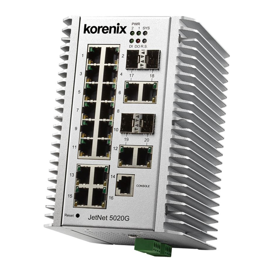
2 Hardware Installation This chapter includes hardware introduction, installation and configuration information. Following topics are covered in this chapter: 2.1 Hardware Introduction System Diagnostic LED, Dimension, Panel Layout 2.2 Wiring Power Inputs 2.3 Wiring Digital Output 2.4 Wiring Earth Ground 2.5 Wiring Fast Ethernet Ports 2.6 Wiring Fiber Ports 2.7 Wiring Combo Ports... - Page 9 Panel Layout The front panel includes RJ-45 based RS232 Console Port, System and Port LEDs, Hardware Reset, Fast/Gigabit Ethernet Port and Gigabit SFP Combo Port interfaces. Grounding, DI/DI and Power1/2 have been designed on the bottom side. Figure of JetNet 5020G, 16+4G Managed Ethernet Switch...
-
Page 10: Wiring Power Inputs
Wiring Power Inputs For redundant DC power inputs. Insert positive and negative wires into V+ and V- contacts respectively of the terminal block connector (Plug-side). Tighten the clamping screws to prevent the loosening of the DC wires. Power 1 and Power 2 support power redundancy and polarity-reverse protection functions. -
Page 11: Wiring Earth Ground
Wiring Earth Ground To ensure the system will not be damaged by noise or any electrical shock, we suggest you to make exact connection into JetNet 5020G with Earth Ground. For DC input, loosen the earth ground screw by screw drive; then tighten the screw after earth ground wire is well connected. -
Page 12: Wiring Fiber Ports
Korenix certificated Gigabit SFP Transceiver. The web UI will show Unknown-Vendor type when choosing the SFP not certificated by Korenix. The certificated SFP transceiver includes 100Base-FX single/multi mode, 100/Gigabit BIDI/WDM, 1000Base-SX/LX single/multi mode ranger from 550m to 80KM. -
Page 13: Wiring Rs-232 Console Cable
Wiring RS-232 Console Cable JetNet 5020G attached one RS-232 DB-9 to RJ-45 cable in the unit box. Connect the RJ-45 connector to the COM port of your PC, open Terminal tool and set up serial settings to 9600, N,8,1. (Baud Rate: 9600 / Parity: None / Data Bit: 8 / Stop Bit: 1) Then you can access CLI interface by console able. - Page 14 Follow the steps below to mount DIN Rail type Switch to the DIN-Rail track: First, insert the upper end of DIN-Rail clip into the back of DIN-Rail track from its upper side. Lightly push the bottom of DIN-Rail clip into the track. Check if DIN-Rail clip is tightly attached on the track.
-
Page 15: Wall Mounting Installation (Optional)
3. Makes sure that all the screws are tightened well. 4. Use the hook holes at the corners of the wall mounting plate to fix the switch on the wall. 5. Wall-mounting plate is optional. If there is a need, please contact Korenix local sales. Wall-Mounting plate and screws... -
Page 16: Safety Warning
2.11 Safety Warning The Equipment intended for installation in a Restricted Access Location. The warning test is provided in user manual. Below is the information: ”For tilslutning af de ovrige ledere, se medfolgende installationsvejledning”. “Laite on liitettava suojamaadoitus-koskettimilla varustettuun pistorasiaan” „Apparatet ma tilkoples jordet stikkontakt“... -
Page 17: Preparation For Management
3.3 Preparation for Telnet console Preparation for Serial Console In JetNet 5020G package, Korenix attached one RS-232 RJ-45 to DB-9 console cable. Please attach RS-232 DB-9 connector to your PC COM port, connect the other end to the Console port of the JetNet 5020G. Note: If you lost the cable, please contact with your sales or follow the pin assignment to buy a new one.. -
Page 18: Preparation For Web Interface
3.2.1 Web Interface Korenix web management page is developed by JAVA. It allows you to use a standard web-browser such as Microsoft Internet Explorer, or Mozila, to configure and interrogate the switch from anywhere on the network. Before you attempt to use the embedded web interface to manage switch operation, verify that your JetNet 5020G is properly installed on your network and that every PC on this network can access the switch via the web browser. - Page 19 3.2.2 Secured Web Interface Korenix web management page also provides secured management HTTPs login. All the configuration commands will be secured and will be hard for the hackers to sniff the login password and configuration commands.
-
Page 20: Preparation For Telnet Console
3.3.1 Telnet Korenix JetNet 5020G supports Telnet console. You can connect to the switch by Telnet and the command lines are the same as what you see by RS232 console port. Below are the steps to open Telnet connection to the switch. - Page 21 Download PuTTY: http://www.chiark.greenend.org.uk/~sgtatham/putty/download.html The copyright of PuTTY Open SSH Client/PuTTY In the Session configuration, enter the Host Name (IP Address of your JetNet 5020G) and Port number (default = 22). Choose the “SSH” protocol. Then click on “Open” to start the SSH session console. 2.
- Page 22 After few seconds, the SSH connection to JetNet 5020G is opened. You can see the login screen as the below figure . (the following is refer to JetNet 5010G) 4. Type the Login Name and its Password. The default Login Name and Password are admin / admin.
-
Page 23: Feature Configuration
4 Feature Configuration This chapter explains how to configure the Managed Switch’s software features. There are four ways to access the switch: Serial console, Telnet, Web browser and SNMP. The Managed Switch Series provides both in-band and out-band configuration methods. You can configure the switch via RS232 console cable if you don’t attach your admin PC to your network, or if you lose the network connection to your Managed Switch. -
Page 24: Command Line Interface Introduction
Command Line Interface Introduction The Command Line Interface (CLI) is the user interface to the switch’s embedded software system. You can view the system information, show the status, configure the switch and receive a response back from the system by keying in a command. There are some different command modes. - Page 25 Global Configuration Mode: Press configure terminal in privileged EXEC mode. You can then enter global configuration mode. In global configuration mode, you can configure all the features that the system provides you. Type interface IFNAME/VLAN to enter interface configuration mode, exit to leave. ? to see the command list.
- Page 26 Type ? to see the command list Available command lists of the (port) Interface configuration mode. Switch(config)# interface fa1 Switch(config-if)# acceptable Configure 802.1Q acceptable frame types of a port. auto-negotiation Enable auto-negotiation state of a given port description Interface specific description dot1x IEEE 802.1x access security control duplex...
- Page 27 Summary of the 5 command modes. Command Main Function Enter and Exit Method Prompt Mode User EXEC This is the first level of access. Enter: Login successfully Switch> User can ping, telnet remote Exit: exit to logout. device, and show some basic Next mode: Type enable to information enter privileged EXEC mode.
- Page 28 Here are some useful commands for you to see these available commands. Save your time in typing and avoid typing error ? To see all the available commands in this mode. It helps you to see the next command you can/should type as well. Switch(config)# interface (?) IFNAME Interface's name vlan...
-
Page 29: Basic Setting
Basic Setting The Basic Setting group provides you to configure switch information, IP address, User name/ Password of the system. It also allows you to do firmware upgrade, backup and restore configuration, reload factory default, and reboot the system. Following commands are included in this group: 4.2.1 Switch Setting 4.2.2 Admin Password 4.2.3 IP Configuration... - Page 30 System Description: JetNet5020G Industrial Managed Ethernet Switch is the name of this product. Firmware Version: Display the firmware version installed in this device. MAC Address: Display unique hardware address (MAC address) assigned by the manufacturer. Once you finish the configuration, click on Apply to apply your settings. Note: Always remember to select Save to save your settings.
- Page 31 4.2.3 IP Configuration This function allows users to configure the switch’s IP address settings. DHCP Client: You can select to Enable or Disable DHCP Client function. When DHCP Client function is enabled, an IP address will be assigned to the switch from the network’s DHCP server.
- Page 32 IPv6 Address: a new IPv6 address can be assigned in this field. Prefix:the size of the subnet or network, and is equivalent to the subnet mask, but expressed in a different way. The default length of the subnet mask is 64bits, and written in decimal value - 64.
- Page 33 Manual Setting: One can select “Manual setting” to change time by hand. Time setting in PC can also be acquired by clicking the button “Get Time from PC”.. After applying the setting, the System Time displayed will be synchronized to PC. Time-zone: Select the time zone where the switch is located.
- Page 34 49 (GMT+05:45) Kathmandu 50 (GMT+06:00) Almaty, Novosibirsk 51 (GMT+06:00) Astana, Dhaka 52 (GMT+06:00) Sri Jayawardenepura 53 (GMT+06:30) Rangoon 54 (GMT+07:00) Bangkok, Hanoi, Jakarta 55 (GMT+07:00) Krasnoyarsk 56 (GMT+08:00) Beijing, Chongqing, Hong Kong, Urumqi 57 (GMT+08:00) Irkutsk, Ulaan Bataar 58 (GMT+08:00) Kuala Lumpur, Singapore 59 (GMT+08:00) Perth 60 (GMT+08:00) Taipei 61 (GMT+09:00) Osaka, Sapporo, Tokyo...
- Page 35 4.2.5 Jumbo Frame What is Jumbo Frame? The typical Ethernet frame is range from 64 to 1518 bytes. This is sufficient for general usages. However, when users want to transmit large files, the files may be divided into many small-size packets. While the transmitting speed becomes slow, long size Jumbo frame can solve the issue.
- Page 36 Manual Binding: the Managed Switch provides a MAC address and IP address binding and removing function. You can type in the specified IP and MAC address, and then click Add to add a new MAC&IP address binding rule for a specified link partner, like PLC or any device without DHCP client function.
- Page 37 DHCP Relay Agent: The DHCP Relay Agent is also known as DHCP Option 82. It can help relay the DHCP Request to remote DHCP server located in different subnet. Note: The DHCP Server cannot work with DHCP Relay Agent at the same time. Relay Agent: Choose Enable or Disable the relay agent.
- Page 38 Technical Tip: Default Configuration File: The switch provides the default configuration file in the system. You can use Reset button, Reload command to reset the system. Running Configuration File: The switch’s CLI allows you to view the latest settings running by the system. The information shown here is the settings you set up but haven’t saved to flash.
- Page 39 4.2.8 Firmware Upgrade In this section, you can update the latest firmware for your switch. We provide the latest firmware in our company Web site. The new firmware may include new features, bug fixes or other software changes. We’ll also provide the release notes for the update as well. For technical viewpoint, we suggest you use the latest firmware before installing the switch to the customer site.
- Page 40 Figure 4.2.8.3 Warning Message. Figure 4.2.8.4 Error Message due to the file error or not a firmware for the switch. Before upgrading firmware, please check if the firmware matches JetNet 5020G. The switch provide protection when upgrading incorrect firmware file, the system would not crash even upload the incorrect firmware.
- Page 41 4.2.9 Laod Default In this section, you can reset all the configurations of the switch to default setting. Click on Reset the system will then reset all configurations to default setting. The system will show you popup message window after finishing this command. Default setting will work after rebooting the switch.
- Page 42 Command Line Switch Setting Switch(config)# hostname WORD Network name of this system System Name Switch(config)# hostname JetNet 5020G Switch(config)# Switch(config)# snmp-server location Taipei System Location Switch(config)# snmp-server contact korecare@korenix.com System Contact Switch# show snmp-server name Display Switch Switch# show snmp-server location...
- Page 43 MAC Address : 001277FF8888 Manufacturing Date : 2015/11/06 Software Information : Loader Version : 1.0.0.0 Firmware Version : 1.0_b1-20160201-16:19:04 Copyright 2006-2015 Korenix Technology Co., Ltd. Switc # show hardware led led information mac mac address Switch# show hardware led Power 1 : On...
- Page 44 Administrative Status : Enable Running-Config) Operating Status : Up DHCP Client : Disable Primary IP Address : 192.168.10.13/24 IPv6 Address : fe80::212:77ff:feff:8888/64 Switch# show running-config Building configuration... Current configuration: hostname Switch vlan 1 ……… interface vlan1 ip address 192.168.10.13/24 no shutdown ip route 0.0.0.0/0 192.168.10.254 spanning-tree mst configuration exit...
- Page 45 secondary Secondary peer Switch(config)# ntp peer primary IPADDRESS IP address of peer Switch (config)# ntp peer primary 192.168.10.120 Switch(config)# clock timezone 60 Time Zone 60 (GMT+08:00) Taipei Note: By typing clock timezone ?, the timezone list will be shown for the user selections. Jumbo Frame Jumbo Frame Type the maximum MTU to enable Jumbo Frame:...
- Page 46 Switch(config-dhcp)# ip dhcp excluded-address 192.168.10.123 Excluded Address Switch(config-dhcp)# ip dhcp static port DHCP Server – Static PORT IP Address Port-IP binding Switch(config-dhcp)# ip dhcp static port 3 111.111.111.111 Switch(config-dhcp)# ip dhcp static 0012.7700.0001 DHCP Server – Static A.B.C.D leased IP address MAC-IP binding Switch(config-dhcp)# ip dhcp static 0012.7700.0001 192.168.10.99...
- Page 47 to see how to save settings to the flash. Note 2: 192.168.10.33 is the TFTP server’s IP and default.conf is the name of the configuration file. In your environment, a different IP address or different file name may be used. Please type adequate TFTP server IP or file name in this command.
-
Page 48: Port Configuration
Port Configuration This chapter delivers guidance on the configuration of switch ports, including port state enable/disable, auto-negotiation, speed, duplex, flow control, rate limit control and port aggregation settings. The view on port status and aggregation information can be also achieved. Following commands are included : 4.3.1 Understand the port mapping 4.3.2 Port Control... - Page 49 In State column, the selected port can be enabled or disabled. Once the port disabled, the port linkage is down and stop to forward any traffic. The default setting is Enable which means all the ports are functional when you receive the device. In Speed/Duplex column, the port speed and duplex mode can be configured, including the following selections : Fast Ethernet Port 1~16 (fa1~fa16): AutoNegotiation, 10M Full Duplex(10 Full), 10M Half...
- Page 50 The description of the columns is as below: Port: Port interface number. Type: 100BASE-TX -> Fast Ethernet copper port. 100BASE-FX -> 100Base-FX Fiber Port. 1000BASE-T -> Gigabit Ethernet Copper port. 1000BASE-X-> Gigabit Fiber Port Link: Link status. Up -> Link UP. Down -> Link Down. State: Enable ->...
- Page 51 4.3.4 Rate Control Rate limiting is a form of flow control used to enforce a strict bandwidth limit at a port. You can program separate transmit (Egress Rule) and receive (Ingress Rule) rate limits at each port, and even apply the limit to certain packet types as described below.
- Page 52 The aggregated ports can interconnect to the other switch which also supports Port Trunking. The Switch Supports 2 types of port trunking. One is Static Trunk, the other is 802.3ad. When the other end uses 802.3ad LACP, you should assign 802.3ad LACP to the trunk. When the other end uses non-802.3ad, you can then use Static Trunk.
- Page 53 This command can be used when connect the switch by 2-port LACP through not-direct connected or shared media, like the Wireless AP or Hub. The end of the switch may not directly detect the failure; the LACP Short Timeout can detect the LACP group failure earlier within 3 seconds.
- Page 54 Flowcontrol off for port 1 set ok! Port Status Switch# show interface fa1 Port Status Interface fastethernet1 Description : N/A Administrative Status : Enable Operating Status : Connected Duplex : Auto (Full) Speed : Auto (100) MTU : 2000 Flow Control : off Default Port VLAN ID: 1 Acceptable Frame Type : All Auto Negotiation : Enable...
- Page 55 Destination Lookup Failure Configuration (Packet multicast Multicast packets Type) SWITCH(config)# storm-control broadcast ? <1~1000000> Rate limit value 1~1000000 Kbits/sec SWITCH(config)# storm-control broadcast 1000 Enables rate limit for Broadcast packets for Port 1 SWITCH(config)# storm-control multicast 1000 Enables rate limit for Multicast packets for Port 1 SWITCH(config)# storm-control dlf 1000 Enables rate limit for Destination Lookup Failue packets for Port1.
- Page 56 Switch(config)# trunk group 2 fa11-12 Can't set trunk group 2 enable! The group 2 is a static aggregation group. Switch# show lacp Display – LACP counters LACP statistical information group LACP group internal LACP internal information neighbor LACP neighbor information port-setting LACP setting for physical interfaces system-id...
-
Page 57: Network Redundancy
The single one Korenix switch can aggregate multiple Rings within itself. All the ports can be configured as the ring port of a ring, each ring has its own Ring ID and the Ring ID will be added to the watchdog packet to monitor the ring status. - Page 58 This page shows how to modify the STP mode and the global STP/RSTP Bridge Configuration. The STP mode includes the STP, RSTP, MSTP and Disable. Please select the STP mode for your system first. The default mode is RSTP enabled. After select the STP or RSTP mode, continue to configure the global Bridge parameters for STP and RSTP.
- Page 59 Note: The bridge priority value must be in multiples of 4096. A device with a lower number has a higher bridge priority. Ex: 4096 is higher than 32768. Note: The Web GUI allows user select the priority number directly. This is the convinent of the GUI design.
- Page 60 Link Type: There are 3 link types for your selection-Auto, P2P and Share. Some of the rapid state transitions that are possible within RSTP depend upon whether the port of concern can only be connected to another bridge (i.e. it is served by a point-to-point LAN segment), or if it can be connected to two or more bridges (i.e.
- Page 61 4.4.3 RSTP Info This page allows you to see the information of the root switch and port status. Root Information: You can see root Bridge ID, Root Priority, Root Port, Root Path Cost and the Max Age, Hello Time and Forward Delay of BPDU sent from the root switch. Port Information: You can see port Role, Port State, Path Cost, Port Priority, Oper P2P mode, Oper edge port mode and Aggregated(ID/Type).
- Page 62 The figure shows there are 2 VLANs/MSTP Instances and each instance has its Root and forwarding paths. A Common Spanning Tree (CST) interconnects all adjuacent MST regions and acts as a virtual bridge node for communications with STP or RSTP nodes in the global network. MSTP connects all bridges and LAN segments with a single Common and Internal Spanning Tree (CIST).
- Page 63 After enabled MSTP mode, then you can go to the MSTP Configuraiton pages. MSTP Region Configuration This page allows configure the Region Name and its Revision, mapping the VLAN to Instance and check current MST Instance configuration. The network can be divided virtually to different Regions.
- Page 64 Instance ID: Select the Instance ID, the available number is 1-15. VLAN Group: Type the VLAN ID you want mapping to the instance. Instance Priority: Assign the priority to the instance. After finish your configuration, click on Add to apply your settings. Current MST Instance Configuration This page allows you to see the current MST Instance Configuration you added.
- Page 65 Path Cost: Enter a number between 1 and 200,000,000. This value represents the “cost” of the path to the other bridge from the transmitting bridge at the specified port. Priority: Enter a value between 0 and 240, using multiples of 16. This is the value that decides which port should be blocked by priority in a LAN.
- Page 66 Click on “Reload“ to reload the MSTP information display. 4.4.7 Multiple Super Ring (MSR) The most common industrial network redundancy is to form a ring or loop. Typically, the managed switches are connected in series and the last switch is connected back to the first one.
- Page 67 Ring Configuration ID: Once a Ring is created, it appears and cannot be changed. Name: This field will show the name of the Ring. If it is not filled in when creating, it will be automatically named by the rule “RingID”. Version: The version of Ring can be changed here.
- Page 68 RDH Ext. ID: Rapid Dual Homing Extension ID. The Extension ID and Ring ID cannot be the same, when dual home to the same foreing network. The Extension ID range from 0 to 7. With the combination of Extension ID(0 to 7) and Ring ID(0 to 31), we can now support up to 256(8*32) different dual homing rings In Rapid Dual Homing, you don’t need to configure specific port to connect to other protocol.
- Page 69 ID: Ring ID. Version: which version of this ring, this field could be Rapid Super Ring, or Super Chain Role: This Switch is RM or nonRM Status: If this field is Normal which means the redundancy is approved. If any one of the link in this Ring is broken, then the status will be Abnormal.
- Page 70 ERPS: Enable or disable ERPS function. ERPS Configuration: Version: ERPS has version 1 and 2. Now we just suport ERPSv1 Node State: The current state of the node, Idle and Protection. Node Role: The rlole of the node, RPL owner and Ring node. The RPL owner is an Ethernet ring node adjacent to the RPL.
- Page 71 Switch(config)# spanning-tree mst configuration Switch(config-mst)# abort exit current mode and discard all changes exit current mode, change to enable mode and apply all changes exit exit current mode and apply all changes instance the mst instance list Print command list name the name of mst region Negate a command or set its defaults...
- Page 72 Apply the setting Switch(config-mst)# quit and go to the apply all mst configuration changes configuration Switch(config)# mode Apply the setting Switch(config-mst)# end and go to the apply all mst configuration changes global mode Switch# Abort the Setting Switch(config-mst)# abort and go to the discard all mst configuration changes configuration Switch(config)# spanning-tree mst configuration...
- Page 73 Port Info Switch# show spanning-tree port detail fa7 (Interface_ID) Rapid Spanning-Tree feature Enabled Port 128.6 as Disabled Role is in Disabled State Port Path Cost 200000, Port Identifier 128.6 RSTP Port Admin Link-Type is Auto, Oper Link-Type is Point-to-Point RSTP Port Admin Edge-Port is Enabled, Oper Edge-Port is Edge Designated root has priority 32768, address 0012.7700.0112 Designated bridge has priority 32768, address 0012.7760.1aec Designated Port ID is 128.6, Root Path Cost is 600000...
- Page 74 -------- -------------- -------- ----------- ------ ----- ----- ----- MST00 0012.77ee.eeee 32768 MST01 0012.77ee.eeee 32768 MST02 0012.77ee.eeee 32768 MSTP Instance Switch# show spanning-tree mst 1 Information ###### MST01 vlans mapped: 2 Bridge address 0012.77ee.eeee priority 32768 (sysid 1) Root this switch for MST01 Port Role State...
- Page 75 default set default Switch(config)# super-ring priority 100 Ring Port Switch(config-multiple-super-ring)# port IFLIST Interface list, ex: fa1,fa3-5,gi8-10 cost path cost Switch(config-multiple-super-ring)# port fa1,fa2 Ring Port Cost Switch(config-multiple-super-ring)# port cost <0-255> valid range is 0 or 255 default set default (128)valid range is 0 or 255 Switch(config-multiple-super-ring)# port cost 100 <0-255>...
- Page 76 Role Transition count 0 Ring State Transition count 1 Ring ID is optional. If the ring ID is typed, this command will only display the information of the target Ring. ERPS show erps Switch# show erps Ethernet Ring Protection Switching (ITU-T G.8032) Version : v1 Ring State...
- Page 77 wtr-timer WTR(Wait-to-restore) Timer guard-timer Guard Timer...
-
Page 78: Vlan
VLAN A Virtual LAN (VLAN) is a “logical” grouping of nodes for the purpose of limiting a broadcast domain to specific members of a group without physically grouping the members together. That means, VLAN allows you to isolate network traffic so that only members of VLAN could receive traffic from the same VLAN members. - Page 79 VLAN Configuration group enables you to Add/Remove VLAN, configure port Ingress/Egress parameters and view VLAN table. Following commands are included in this group: 4.5.1 VLAN Port Configuration 4.5.2 VLAN Configuration 4.5.3 GVRP Configuration 4.5.4 VLAN Table 4.5.5 CLI Commands of the VLAN 4.5.1 VLAN Port Configuration VLAN Port Configuration allows you to set up VLAN port parameters to specific port.
- Page 80 Tunnel Mode: This is the new command for QinQ. The command includes None, 802.1Q Tunnel and 802.1Q Tunnel Uplink. The figure shows the relationship between 802.1Q Tunnel and 802.1Q Tunnel Uplink. Following is the modes you can select. None: Remian VLAN setting, no QinQ. 802.1Q Tunnel: The QinQ command applied to the ports which connect to the C-VLAN.
- Page 81 4.5.2 VLAN Configuration In this page, you can assign Management VLAN, create the static VLAN, and assign the Egress rule for the member ports of the VLAN. Figure 4.5.2.1 Web UI of the VLAN Configuration. Management VLAN ID: The switch supports management VLAN. The management VLAN ID is the VLAN ID of the CPU interface so that only member ports of the management VLAN can ping and access the switch.
- Page 82 Note: Before you change the management VLAN ID by Web and Telnet, remember that the port attached by the administrator should be the member port of the management VLAN; otherwise the administrator can’t access the switch via the network. Note: JetNet 5020G supports max 255 groups of VLAN. Static VLAN Configuration You can see the created VLANs and specify the egress (outgoing) port rule to be Untagged or Tagged here.
- Page 83 4.5.3 GVRP configuration GVRP allows users to set-up VLANs automatically rather than manual configuration on every port of every switch in the network. In low volume and stable network, the GVRP can reduce the configuration effort. For high volume and high secure request network, the Static VLAN configuration is always preferred.
- Page 84 After created the VLAN, the status of this VLAN will remain in Unused status until you add ports to the VLAN. 4.5.5 CLI Commands of the VLAN Command Lines of the VLAN port configuration, VLAN configuration and VLAN table display Feature Command Line VLAN Port Configuration...
- Page 85 Duplex : Auto Speed : Auto MTU : 2000 Flow Control :off Default Port VLAN ID: 2 Acceptable Frame Type : Vlan Tagged Only Auto Negotiation : Enable Loopback Mode : None STP Status: disabled Default CoS Value for untagged packets is 0. Mdix mode is Auto.
- Page 86 Create VLAN (2) Switch(config)# vlan 2 vlan 2 success Switch(config)# interface vlan 2 Switch(config-if)# Note: In CLI configuration, you should create a VLAN interface first. Then you can start to add/remove ports. Default status of the created VLAN is unused until you add member ports to it.
- Page 87 Gvrp is enabled on the switch! Configure GVRP timer Switch(config)# inter fa1 Switch(config-if)# garp join-timer Join timer /Leave timer/ <10-10000> the timer values LeaveAll timer Switch(config-if)# garp join-timer 20 Garp join timer value is set to 20 centiseconds on port 1! Management VLAN Management VLAN Switch(config)# int vlan 1 (Go to management VLAN)
-
Page 88: Private Vlan
Private VLAN The private VLAN helps to resolve the primary VLAN ID shortage, client ports’ isolation and network security issues. The Private VLAN provides primary and secondary VLAN within a single switch. Primary VLAN: The uplink port is usually the primary VLAN. A primary VLAN contains promiscuous ports that can communicate with lower Secondary VLANs. - Page 89 Community: The VLAN is the Community VLAN. The member ports of the VLAN can communicate with each other. 4.6.2 PVLAN Port Configuration PVLAN Port Configuration page allows configure Port Configuration and Private VLAN Association. Private VLAN Association Secondary VLAN: After the Isolated and Community VLAN Type is assigned in Private VLAN Configuration page, the VLANs are belonged to the Secondary VLAN and displayed here.
- Page 90 For example: 1. VLAN Create: VLAN 2-5 are created in VLAN Configuration page. 2. Private VLAN Type: VLAN 2-5 has its Private VLAN Type configured in Private VLAN Configuration page. VLAN 2 is belonged to Primary VLAN. VLAN 3-5 are belonged to secondary VLAN (Isolated or Community). 3.
- Page 91 4.6.3 Private VLAN Information This page allows you to see the Private VLAN information. 4.6.4 CLI Command of the PVLAN Command Lines of the Private VLAN configuration Feature Command Line Private VLAN Configuration Create VLAN Switch(config)# vlan 2 vlan 2 success Switch(config-vlan)# End current mode and change to enable mode exit...
- Page 92 Primary Type Switch(config-vlan)# private-vlan primary Switch(config-vlan)# no private-vlan primary Isolated Type Switch(config-vlan)# private-vlan isolated Switch(config-vlan)# no private-vlan isolated Community Type Switch(config-vlan)# private-vlan community Switch(config-vlan)# no private-vlan community Private VLAN Port Configuraiton Go to the port Switch(config)# interface (port_number, ex: gi9) configuraiton Switch(config-if)# switchport private-vlan host-association Set the private VLAN host association...
- Page 93 isolated community community fa7,gi9 primary Host List Switch# show vlan private-vlan port-list Ports Mode Vlan ----- ----------- ---- normal normal normal normal normal normal host host host promiscuous 2 Running Config Switch# show run Information Building configuration... Current configuration: hostname Switch vlan learning independent vlan 1 Private VLAN Type...
-
Page 94: Traffic Prioritization
interface gigabitethernet10 switchport access vlan add 2,5 switchport trunk native vlan 2 switchport mode private-vlan promiscuous switchport private-vlan mapping 2 add 3-5 ……… …….. Traffic Prioritization Quality of Service (QoS) provides traffic prioritization mechanism which allows users to deliver better service to certain flows. QoS can also help to alleviate congestion problems and ensure high-priority traffic is delivered first. - Page 95 Queue Scheduling You can select the Queue Scheduling rule as follows: Use a strict priority scheme. Packets with higher priority in the queue will always be processed first, except that there is no packet with higher priority. Use Weighted Round Robin scheme. This scheme allows users to assign new weight ratio for each class.
- Page 96 After configuration, press Apply to enable the settings. 4.7.4 DSCP-Priority Mapping This page allows you to modify DSCP values to Priority mapping table. The system provides 0~63 DSCP priority levels. Each DSCP level can be assigned into 8 different physical queue, from lowest 0 to highest 7. After configuration, press Apply to enable the settings.
- Page 97 4.7.5 CLI Commands of the Traffic Prioritization Command Lines of the Traffic Prioritization configuration Feature Command Line QoS Setting Queue Scheduling – Switch(config)# qos queue-sched Strict Priority Strict Priority wrr Weighted Round Robin Switch(config)# qos queue-sched sp The queue scheduling scheme is setting to Strict Priority. Queue Scheduli–g - Switch(config)# qos queue-sched wrr <1-10>...
- Page 98 CoS-Queue Mapping Format Switch(config)# qos cos-map PRIORITY Assign an priority (7 highest) Switch(config)# qos cos-map 1 QUEUE Assign an queue (0-7) Note: Format: qos cos-map priority_value queue_value Map CoS 0 to Queue 1 Switch(config)# qos cos-map 0 1 The CoS to queue mapping is set ok. Map CoS 1 to Queue 0 Switch(config)# qos cos-map 1 0 The CoS to queue mapping is set ok.
- Page 99 1 | 1 1 1 1 1 1 2 2 2 2 2 | 2 2 2 2 3 3 3 3 3 3 3 | 3 3 4 4 4 4 4 4 4 4 4 | 5 5 5 5 5 5 5 5 6 6 5 | 6 6 6 6 6 6 7 7 7 7 6 | 7 7 7 7...
-
Page 100: Multicast Filtering
Multicast Filtering For multicast filtering, JetNet 5020G uses IGMP Snooping technology. IGMP (Internet Group Management Protocol) is an Internet Protocol that provides a way for internet device to report its multicast group membership to adjacent routers. Multicasting allows one computer on the internet to send data to a multitude of other computers that have identified themselves as being interested in receiving the originating computers data. - Page 101 Snooping function, or select the “IGMP Snooping” global setting for all VLANs.. Then press Apply. In the same way, you can also Disable IGMP Snooping for certain VLANs. Filtering Mode Setting: you can select Filtering Mode on this Page. Send to Query Ports: The unknown multicast will be sent to the Query ports. The Query port means the port received the IGMP Query packets.
- Page 102 4.8.2 IGMP Query This page allows users to configure IGMP Query feature. Since the Managed Switch can only be configured as the member port of the management VLAN, IGMP Query can only be enabled on the management VLAN. If you want to run IGMP Snooping feature in several VLANs, you should notice that whether each VLAN has its own IGMP Querier first.
- Page 103 Once you finish configuring the settings, click on Apply to apply your configuration. 4.8.4 GMRP To enable the GMRP configuration, the Global GMRP Configuration should be enabled first. And all the port interfaces should enable GMRP learning as well. Then the switch exchange the IGMP Table with other switches which is also GMRP-aware devices.
- Page 104 4.8.5 CLI Commands of the Multicast Filtering Command Lines of the multicast filtering configuration Feature Command Line IGMP Snooping IGMP Snoopi–g - Switch(config)# ip igmp snooping Global IGMP snooping is enabled globally. Please specify on which vlans IGMP snooping enables Switch(config)# ip igmp snooping <?>...
- Page 105 IGMP Query version Switch(config-if)# ip igmp version 1 Switch(config-if)# ip igmp version 2 Disable Switch(config)# int vlan 1 Switch(config-if)# no ip igmp Display Switch# sh ip igmp interface vlan1 enabled: Yes version: IGMPv2 query-interval: 125s query-max-response-time: 10s Switch# show running-config ….
-
Page 106: Snmp
SNMP Simple Network Management Protocol (SNMP) is a protocol used for exchanging management information between network devices. SNMP is a member of the TCP/IP protocol suite. The Managed Switch series support SNMP v1 and v2c and V3. (Web Managed Switch doesn’t support SNMP feature.) An SNMP managed network consists of two main components: agents and a manager. - Page 107 4.9.2 SNMP V3 Profile SNMP v3 can provide more security functions when the user performs remote management through SNMP protocol. It delivers SNMP information to the administrator with user authentication; all of data between JetNet 5020G and the administrator are encrypted to ensure secure communication.
- Page 108 This page allows users to Enable SNMP Trap, configure the SNMP Trap server IP, Community name, and trap version V1 or V2c. After configuration, you can see the change of the SNMP pre-defined standard traps and Korenix pre-defined traps. The pre-defined traps can be found in Korenix private MIB. 4.9.4...
- Page 109 Set SNMP trap enable ok. SNMP Trap Server IP Switch(config)# snmp-server host 192.168.10.33 without specific SNMP trap host add OK. community name SNMP Trap Server IP Switch(config)# snmp-server host 192.168.10.33 version 1 with version 1 and private community SNMP trap host add OK. Note: private is the community name, version 1 is the SNMP version SNMP Trap Server IP...
-
Page 110: Security
4.10 Security JetNet 5020G provides several security features for you to secure your connection. The Filter Set is also known as Access Control List. The ACL feature includes traditional Port Security and IP Security. Following commands are included in this group: 4.10.1 Filter Set (Access Control List) 4.10.2 IEEE 802.1x 4.10.3 CLI Commands of the Security... - Page 111 MAC Filter (Port Security): The MAC Filter allows user to define the Access Control List for specific MAC address or a group of MAC addresses. Filter ID/Name: The name for this MAC Filter entry. Action: Permit to permit traffic from specified sources. Deny to deny traffic from those sources.
- Page 112 Once you finish the settings, click on Add to apply your configuration. You can see below screen is shown. Example of the below Entry: Permit Source MAC 0012.7700.0000” to Destination MAC 0012.7700.0002”. “ “ Once you finish configuring the settings, click on Apply to apply your configuration. IP Filter: Type ID/Name when select IP Filter.
- Page 113 IP Standard Access List: This kind of ACL allows user to define filter rules according to the source IP address. IP Extended Access List: This kind of ACL allows user to define filter rules according to the source IP address, destination IP address, Source TCP/UDP port, destination TCP/UDP port and ICMP type and code.
- Page 114 allowance 11111111.11111111. All IP addresses. Or a mask: 11111111.11111111 255.255.255.255 Host 0.0.0.0 Only the Source or Destination host. 0.0.0.3 0.0.0.(00000011) 0.0.0.7 0.0.0.(00000111) 0.0.0.15 0.0.0.(11111111) …. Note: The mask is a wildcard mask: the high-order bits of the mask that are binary zeros determine how many corresponding high-order bits in the IP address are significant.
- Page 115 Filter Attach (Access Control List) After configured the ACL filter rules, remember associate this filter with the physical ports. Then the port has the capability to filter traffic/attach based on the packets lost. 4.10.2 IEEE 802.1x 4.10.2.1 802.1X configuration IEEE 802.1X is an IEEE standard for port based network access control, which provides authentication to the divices attached to a LAN port.
- Page 116 System AuthControl: To enable or disable the 802.1x authentication. Authentication Method: Radius is a authentication server that provide key for authentication, with this method, user must connect switch to server. If user select Local for the authentication method, switch use the local user data base which can be create in this page for authentication.
- Page 117 4.10.2.2 802.1x Port Configuration After the configuration of Radius Server or Local user list, user also need configure the authentication mode, authentication behavior, applied VLAN for each port and permitted communication. The following information will explain the port configuration. Once you finish configuring the settings, click on Apply to apply your configuration. Port control: Force Authorized means this port is authorized;...
- Page 118 Quiet Period: When authentication failed, Switch will wait for a period and try to communicate with radius server again. Tx period: the time interval of authentication request. Supplicant Timeout: the timeout for the client authenticating Sever Timeout: The timeout for server response for authenticating. Click Initialize Selected to set the authorize state of selected port to initialize status.
- Page 119 list Print command list Negate a command or set its defaults quit Exit current mode and down to previous mode Add IP Standard Switch(config)# ip access-list access list extended Extended access-list standard Standard access-list Switch(config)# ip access-list standard <1-99> Standard IP access-list number <1300-1999>...
- Page 120 Extended access list Switch(config-ext-acl)#permit Any Internet Protocol Transmission Control Protocol User Datagram Protocol icmp Internet Control Message Protocol Switch(config-ext-acl)#permit ip A.B.C.D Source address Any source host host A single source host Switch(config-ext-acl)#permit ip 192.168.10.1 A.B.C.D Source wildcard bits Switch(config-ext-acl)#permit ip 192.168.10.1 0.0.0.1 A.B.C.D Destination address Any destination host host...
- Page 121 Switch(config)# radius server-ip Switch(config)# dot1x radius Switch(config)# dot1x radius server-ip 192.168.10.120 key 1234 RADIUS Server Port number NOT given. (default=1812) RADIUS Accounting Port number NOT given. (default=1813) RADIUS Server IP : 192.168.10.120 RADIUS Server Key : 1234 RADIUS Server Port : 1812 RADIUS Accounting Port : 1813 Switch(config)# radius server-ip...
- Page 122 MaxReq ReAuthPeriod : 3600 Seconds QuietPeriod : 60 Seconds TxPeriod : 30 Seconds SupplicantTimeout : 30 Seconds ServerTimeout : 30 Seconds GuestVlan HostMode : Single operControlledDirections : Both adminControlledDirections : Both Switch# show dot1x radius RADIUS Server IP : 192.168.10.100 RADIUS Server Key : radius-key RADIUS Server Port : 1812 RADIUS Accounting Port : 1813...
-
Page 123: Warning
4.11 Warning JetNet 5020G provides several types of Warning features for you to remotely monitor the status of end devices or the change of your network. The features include Fault Relay, System Log and SMTP E-mail Alert. Following commands are included in this group: 4.11.1 Fault Relay 4.11.2 Event Selection 4.11.3 Syslog Configuration... - Page 124 Select Ring Failure. When the Ring topology is changed, the system will short Relay Output and light the DO LED. Event Type: Ping Failure IP Address: IP address of the target remote device. If pinging failure, the Relay will be activated in Status “On”(closed, LED DO=Red).
- Page 125 4.11.2 Event Selection Event Types can be divided into two basic groups: System Events and Port Events. System Events are related to the overall function of the switch, whereas Port Events related to the activity of specific ports...
- Page 126 Warning Event is sent when….. System Event Device Cold Start Power is cut off and then reconnected. Device Warm Start Reboot the device by CLI or Web UI. Authentication failure An incorrect password, SNMP Community String is entered Time Synchronize Accessing to NTP Server is failure.
- Page 127 4.11.4 SMTP Configuration Jet 5020G supports E-mail Warning feature. The switch will send the occurred events to remote E-mail server. The receiver can notified by E-mail. The E-mail warning machenism conforms to SMTP standard. This page allows you to enable E-mail Alert, assign the SMTP Server IP, Sender E-mail, and Receiver E-mail.
- Page 128 Rcpt E-mail Address 4 The fourth email address to receive email alert from Managed Switch (Max. 40 characters) Once you finish configuring the settings, click on Apply to apply your configuration. 4.11.5 CLI Commands Command Lines of the Warning configuration Feature Command Line Relay Output...
- Page 129 Switch(config)# smtp-server server 192.168.10.100 ACCOUNT SMTP server mail account, ex: admin@korenix.com Switch(config)# smtp-server server 192.168.10.100 admin@korenix.com SMTP Email Alert set Server: 192.168.10.100, Account: admin@korenix.com ok. admin@example. Receiver mail Switch(config)# smtp-server receipt admin@example. SMTP Email Alert set receipt 1: com ok.
- Page 130 example Server: 192.168.10.100, Account: admin@ .com Authentication: Enabled Username: admin, Password: admin SMTP Email Alert Receipt: admin example Receipt 1: .com Receipt 2: Receipt 3: Receipt 4:...
-
Page 131: Monitor And Diagnostic
4.12 Monitor and Diagnostic JetNet 5020G provides several types of features for you to monitor the status of the switch or diagnose the problems encountered. The features include MAC Address Table, Port Statistics, Port Mirror, Event Log and Ping. Following commands are included in this group: 4.12.1 MAC Address Table 4.12.2 Port Statistics 4.12.3 Port Mirroring... - Page 132 4.12.2 Port Statistics In this page, you can view operation statistics for each port. The statistics that can be viewed include Link Type, Link State, Rx Good, Rx Bad, Rx Abort, Tx Good, Tx Bad and Collision. Rx means the received packet while Tx means the transmitted packets. Note: If you see many Bad, Abort or Collision counts increased, that may mean your network cable is not connected well, the network performance of the port is poor…etc.
- Page 133 4.12.3 Port Mirroring Port mirroring (also called port spanning) is a tool that allows you to mirror the traffic from one or more ports onto another port, without disrupting the flow of traffic on the original port. Any traffic that goes into or out of the Source Port(s) will be duplicated at the Destination Port.
- Page 134 4.12.4 Event Log In the 4.10.3, we have introduced System Log feature. When System Log Local mode is selected, JetNet 5020G will record occurred events in local log table. This page shows this log table. The entry includes the index, occurred data and time and content of the events. Click on Clear to clear the entries.
- Page 135 4.12.6 Ping Utility This page provides Ping Utility for users to ping remote device and check whether the device is alive or not. Type Target IP address of the target device and click on Start to start the ping. After few seconds, you can see the result in the Result field.
- Page 136 Modbus/TCP that it can be polled through Ethernet. Thus the Modbus/TCP master can read or write the Modbus registers provided by the Industrial Ethernet Switch. Korenix JetNet 5428G implements the Modbus/TCP registers into the latest firmware. The registers include the System information, firmware information, IP address, interfaces’...
- Page 137 Word 1 Hi byte = ‘T’ Word 1 Lo byte = ‘N’ Word 2 Hi byte = ‘e’ Word 2 Lo byte = ‘t’ Word 3 Hi byte = ‘5’ Word 3 Lo byte = ‘4’ Word 4 Lo byte = ‘2’ Word 4 Hi byte = ‘8’...
- Page 138 Ex: MAC = 01-02-03-04-05-06 Word 0 Hi byte = 0x01 Word 0 Lo byte = 0x02 Word 1 Hi byte = 0x03 Word 1 Lo byte = 0x04 Word 2 Hi byte = 0x05 Word 2 Lo byte = 0x06 0x020F to 241 words Reserved address space...
- Page 139 0x0410 1 word 0x0000:Off 0x0001:On 0xFFFF: unavailable 0x0411 1 word 0x0000:Off 0x0001:On 0xFFFF: unavailable 0x0412 1 word 0x0000:Off 0x0001:On 0xFFFF: unavailable 0x0413 1 word 0x0000:Off 0x0001:On 0xFFFF: unavailable 0x0414 to 12 words Reserved address space 0x041F 0x0420 1 word 0x0000:Off 0x0001:On 0x0421 1 word...
- Page 140 0xFFFF: unavailable 0x1240 to 1 word Duplex 0x125F 0x0000: half 0x0001: full 0x0003: auto (half) 0x0004: auto (full) 0x0005: auto 0xFFFF: unavailable 0x1260 to 1 word Speed 0x127F 0x0001: 10 0x0002: 100 0x0003: 1000 0x0004: 2500 0x0005: 10000 0x0101: auto 10 0x0102: auto 100 0x0103: auto 1000 0x0104: auto 2500...
- Page 141 0x0001: enable 0xFFFF: unavailable 0x1340 to 1 word Loopback Mode 0x135F 0x0000: none 0x0001: MAC 0x0002: PHY 0xFFFF: unavailable 0x1360 to 1 word STP Status 0x137F 0x0000: disabled 0x0001: blocking 0x0002: listening 0x0003: learning 0x0004: forwarding 0x1380 to 1 word Default CoS Value for untagged packets 0x139F 0x13A0 to...
- Page 142 SFP DDM Information (32 Ports) 0x1800 to 1 words Temperature 0x181F 0x1820 to 2 words Alarm Temperature 0x185F 0x1860 to 1 words Tx power 0x187F 0x1880 to 2 words Warning Tx power 0x18BF 0x18C0 to 1 words Rx power 0x18DF 0x18E0 to 2 words Warning Rx power...
- Page 143 0x22C0 to 2 words Filtered frames 0x22FF 0x2300 to 2 words RxError 0x233F 0x2340 to 2 words FCSError 0x237F 0x2380 to 2 words Collisions 0x23BF 0x23C0 to 2 words Dropped Frames 0x23FF 0x2400 to 2 words Last Activated SysUpTime 0x243F 0x2440 to 191 words Reserved address space...
- Page 144 0x27FF 0x2800 to 2 words FCSError 0x283F 0x2840 to 447 words Reserved address space 0x29FF Number of frames received and transmitted with a length(in octets) 0x2A00 to 2 words 0x2A3F 0x2A40 to 2 words 65 to 127 0x2A7F 0x2A80 to 2 words 128 to 255 0x2ABF...
- Page 145 ------------------- --------------- ------- ------------------------ 000f.b079.ca3b Dynamic 0012.7701.0386 Dynamic 0012.7710.0101 Static 0012.7710.0102 Static 0012.77ff.0100 Management ***** MULTICAST MAC ADDRESS ***** Vlan Mac Address Status Ports ---- --------------- ---- ------- -------------------------- 0100.5e40.0800 0100.5e7f.fffa fa4,fa6 Show MAC Address Switch# show mac-address-table dynamic Table – Dynamic Learnt Destination Address Address Type Vlan Destination Port...
- Page 146 Switch(config)# mirror source fa1-2 both Mirror source fa1-2 both set ok. Note: Select source port list and TX/RX/Both mode. Select Destination Port Switch(config)# mirror destination fa6 both Mirror destination fa6 both set ok Display Switch# show mirror Mirror Status : Enabled Ingress Monitor Destination P rt : fa6 Egress Monitor Destination P rt : fa6 Ingress Source Po ts :fa1,fa2,...
-
Page 147: Device Front Panel
4.13 Device Front Panel The command – “Device Front Panel” that allows you to check the LED status of the switch from Web browser. You can see LED and link status of the Power, DO, R.M. and Font Ports. Below is the example of managed Switch. Different model has its own front panel display Feature On / Link UP... -
Page 148: Save To Flash
4.14 Save to Flash Save Configuration allows you to save any configuration you just made to the Flash. Powering off the switch without clicking on Save Configuration will cause loss of new settings. After selecting Save Configuration, click on Save to Flash to save your new configuration. -
Page 149: Logout
4.15 Logout The switch provides 2 logout methods. The web connection will be logged out if you don’t input any command after 30 seconds. The Logout command allows you to manually logout the web connection. Click on Yes to logout, No to go back the configuration page. Command Lines: Feature Command Line... -
Page 150: Appendix
We will keep updating the certification process and posting the certificated SFP transceivers on our web site. You can refer to Korenix web site or contact local sale rep for the latest selection guide on SFP transceivers. Note: Poor SFP transceivers may result in poor network performance or can’t meet up claimed distance or operation temperature. - Page 151 Specification Technology Standard IEEE 802.3u 10Base-T Ethernet IEEE 802.3u 100Base-TX Fast Ethernet IEEE 802.3u 100Base-FX Fast Ethernet Fiber IEEE 802.3ab 1000Base-T Gigabit Ethernet copper IEEE 802.3z Gigabit Ethernet Fiber IEEE 802.3x Flow Control and back-pressure IEEE 802.1AB Link Layer Discovery Protocol (LLDP) IEEE 802.1p Class of Service (CoS) IEEE 802.1Q VLAN and GVRP IEEE 802.1Q Double Tag VLAN ( QinQ)
- Page 152 SNMP MIB MIB II, Bridge MIB, Ethernet Like MIB, VLAN MIB, IGMP MIB< Private MIB Management Utility Supports Korenix windows utility with IEEE 802.1AB link Layer Protocol for Device finding and Link Topology Discovery Network Time Protocol NTP protocol with daylight saving and localize time sync function...
- Page 153 Network Redundancy Multiple Super Ring (MSR ) New generation Korenix Ring Redundancy Technology, Includes Rapid Super Ring, Rapid Dual Homing, TrunkRing , MultiRing , Super Chain and backward compatible with legacy Super Ring Rapid Dual Homing (RDH Multiple uplink paths to one or multiple upper Switch, up to 256 Groups...
- Page 154 10/100Mbps link Amber off) Pwr: Power Ready ( Green On) Sys: System Ready (Green On), System on booting/update (Green Blinking) DI/DO: Digital Input (RED On), Dry Relay Active (RED On) R.S.: Green on (Ring normal)/Blinking (wrong ring port connective), Amber on (Ring abnormal) / Blinking (device’s ring port failed) Power Requirement System Power...
- Page 155 Less Time At Work! Fewer Budget on applications! The Korenix business idea is to let you spend less time at work and fewer budget on your applications. Do you really want to go through all the troubles but still end up with low quality products and lousy services? Definitely not! This is why you need Korenix.
- Page 156 Business service : sales@korenix.com Customer service: koreCARE@korenix.com...
Need help?
Do you have a question about the JetNet 5020G Series and is the answer not in the manual?
Questions and answers