Table of Contents
Advertisement
Quick Links
Advertisement
Table of Contents

Related Manuals for IWILL P4SE Series


Summary of Contents for IWILL P4SE Series
- Page 1 IWILL P4SE Series Motherboard User’ s Manual...
- Page 2 This publication, including all photographs, illustrations and software, is protected under international copyright laws, with all rights reserved. Neither this manual, nor any of the material contained herein, may be reproduced without the express written consent of the manufacturer. IWILL © Copyright 2003 User’ s Manual...
-
Page 3: Table Of Contents
Table of Contents 1: Introduction .........… ....… … .… … … ..… … … ..1-1 About This Manual ....… ........… … … … … … .… … … … .. 1-2 Package Contents ..… … … … … ..… … … … … ............ 1-2 2: Hardware Configuration ...…... - Page 4 PC Health Status ..........… … … … … … … … … … ....4-8 IWILL Smart Setting ........… … … … … … … … … … … ..... 4-8 Load Fail-Safe Defaults ......… … … … … … … … … … ......4-9 Load Optimized Defaults ......…...
-
Page 5: 1: Introduction
Intel® Pentium® 4 processor. The motherboard accommodates Dual Channel 266/333/400 MHz DDR SDRAM using four DIMM memory sockets. Five 32-bit PCI slots provide expansion flexibility. The P4SE Series motherboard uses the latest Intel® 865 family chipset to integrate all system control functions. -
Page 6: About This Manual
5. Drivers and Utilities, explains how to use the bundled software drivers and utilities. 6. Specifications, lists the motherboard’s technical specifications. Package Contents The motherboard package contains the following items: 1. P4SE Series motherboard 2. IDE connector cable 3. Floppy Disk Drive connector cable 4. Rear I/O Shield 5. -
Page 7: 2: Hardware Configuration
Chapter 2 2: Hardware Configuration This chapter describes the motherboard layout and shows the location, function, and configuration of key components, including sockets, slots, connectors and jumpers as well as the external I/O ports. Before installing this motherboard read the following pages carefully for location and function of these items. -
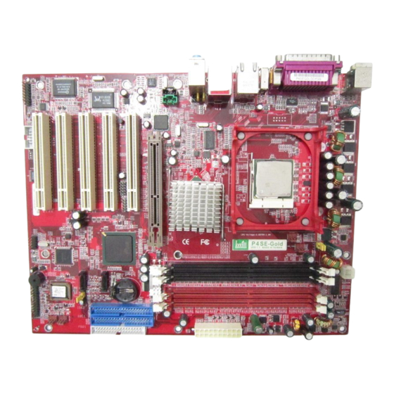
Page 8: Motherboard Layout
P4SE Series Motherboard Motherboard Layout The location of motherboard components is shown below. P4SE 2 – 2 User’ s Manual... -
Page 9: Motherboard Layout Key
Accelerated Graphics Port DDRA1, A2, B1, B2 DIMM sockets for DDR SDRAM PCI1~ PCI5 32_bit PCI expansion slots Connectors Function J1394_2 Firewire internal connectors (P4SE-Gold/P4SG-Gold only) ATX 12V power connector JATXPWR1 JATXPWR2 Connectors for power supply JPANEL1 Front panel feature connector... -
Page 10: Jcmos1: Clear Cmos Jumper
P4SE Series Motherboard JCMOS1: Clear CMOS Jumper This jumper switch, JCMOS1, clears the CMOS Setup configuration that is stored in the real-time clock’s CMOS memory. If configuration becomes corrupted, or if the CMOS settings are changed to an unsuitable configuration, the motherboard may not work properly. JCMOS1 lets you delete the configuration data stored in CMOS memory and reset the CMOS to the Optimized Defaults. -
Page 11: Jcpus1, Jcpus2: Frontside Bus Clock Frequency Selection
Chapter 2 JCPUS1, JCPUS2: Frontside Bus Clock Frequency These two jumper switches, JCPUS1 and JCPUS2, set the clock frequency used to generate the FSB speed, 100MHz~200MHz. JAUDIO1: Audio for Front Panel This jumper, JAUD1, allows users to switch audio function to the front panel if front panel is installed. -
Page 12: Cpu Socket & Cooling Fan / Heatsink Frame
P4SE Series Motherboard CPU Socket & Cooling Fan / Heatsink Frame The mPGA478B CPU socket supports a 478-pin Intel Pentium 4 processor. The Pentium 4 CPU requires a cooling fan/heatsink, which attaches to the board using a retention mechanism mounting frame. See the section on installing the CPU in Chapter 3. -
Page 13: Atx12V Power Connectors
Chapter 2 ATX12V Power Connectors The two power connectors let you attach two leads from an ATX12V power supply to the motherboard. The ATX12V standard requires a 20-pin ATX connector plus a 4-pin ATX12V connector. See the connector diagrams below. ATX2X2, 12 V processor core voltage connector JATXPWR2... -
Page 14: System Memory Sockets
P4SE Series Motherboard System Memory Sockets These DIMM system memory sockets support 400MHz (PC3200) or 333MHz (PC2700) or 266MHz (PC2100) DDR SDRAM system memory modules. See the section on installing memory in Chapter 3. PCI Expansion Slots The PCI expansion slots let you install additional system hardware via add-on cards. There are five 32- bit, 33MHz slots that are compliant with PCI 2.1/2.2 on this motherboard. -
Page 15: Drive Connectors
Chapter 2 Drive Connectors There are drive connectors on the motherboard for connecting IDE and floppy disk drives. FDD1: Floppy Disk Drive Connector The connector FDD lets you attach one floppy disk drive to the motherboard using a standard FDD ribbon cable. IDE1, IDE2: IDE Drive Connectors The two IDE drive connectors are marked IDE1, the primary channel, and IDE2, the secondary channel. -
Page 16: Sata1, Sata2: Serial Ata Drive Connectors
P4SE Series Motherboard SATA1, SATA2: Serial ATA Drive Connectors There are two Serial ATA connectors on the motherboard. Each connector supports one drive, which connects to the motherboard with a Serial ATA cable. The motherboard comes with two Serial ATA cables and one power core for user’ s convenience. -
Page 17: Jcdin1 & Jaux1: Audio Connectors
Chapter 2 JCDIN1 & JAUX1: Audio Connectors These two connectors, JCDIN1 and JAUX1, let you attach audio-in cables from internal peripherals, such as a CD-ROM or DVD-ROM drive. The connectors provide an audio input connection between a device and the integrated audio subsystem. J1394_2: IEEE-1394 Connectors The connector, J1394_2, provide onboard support for devices using the IEEE-1394 standard. -
Page 18: Jpanel1: Front Panel Connector
P4SE Series Motherboard JPANEL1: Front Panel Connector This connector, J23, connects the following system housing front panel features: • Reset Switch (Reset in diagram) • IDE device LED (IDE LED in diagram) • ACPI Suspend LED (ACPI in diagram) •... - Page 19 Chapter 2 JCFAN1, JNB_FAN1, JSFAN1, JSFAN2: CPU & System Fan Connectors These 3-pin connectors provide power to the CPU cooling fan (JCFAN1), to North Bridge cooling fan (JNB_FAN1), to the System cooling fans (SFAN1, SFAN2). A temperature monitor detects the CPU and internal system temperatures. You can set a system shutdown temperature in the PC Health section of the CMOS Setup Utility.
-
Page 20: Jgame1: Gameport Connector
External I/O Ports On the rear edge of the motherboard there are several external Input/Output ports. These ports are color coded for easy identification. Rear I/O of P4SE-Gold/P4SG-Gold For P4SG-Gold, COM port will be VGA port Rear I/O of P4SE/P4SG... -
Page 21: Ps/2 Ports
USB3 USB2 USB4 Gigabit Ethernet Port (P4SE-Gold/P4SG-Gold only) The Gigabit Ethernet Port is an RJ-45 connector for standard Cat 5 LAN cabling. The connector attaches to the onboard Intel Kenai-II CSA Gigabit Ethernet LAN controller. It does not matter if the system is on when connecting or disconnecting a LAN cable. -
Page 22: Com1 Serial Port
The Parallel port connects the system to devices that have a parallel interface. This port is generally used to connect a printer to the system. IEEE-1394 Port (P4SE-Gold/P4SG-Gold only) The IEEE-1394 port is a 6-pin connector for connecting to devices of IEEE std 1394a-2000 interface. -
Page 23: Audio Jacks
Chapter 2 Audio Jacks The audio jacks are for connecting external audio devices to the onboard audio subsystem. The three audio jacks are: Line In: provides audio input connector for an external audio source. Speaker: offers output to two stereo speakers. Mic: this jack is for plugging in a computer microphone. -
Page 24: 3: Motherboard Installation
Please read the sections below and follow the instructions carefully. Installing a CPU The P4SE Series motherboard supports the Intel Pentium 4 processor. You must install both the Intel Pentium 4 and its cooling assembly carefully and in accordance with the procedures below. -
Page 25: Selecting A Processor
Chapter 3 Selecting a Processor This motherboard supports all Intel Pentium 4 processors. The motherboard’s BIOS automatically detects the required settings and configures the CMOS Setup Utility. Installing the Processor It is important to review all of the instructions before beginning the installation procedure. Carefully handle the processor by its edges, and take all precautions against electrostatic discharge. - Page 26 P4SE Series Motherboard 2. Position the CPU above the socket such that its marked corner matches the base of the socket lever. 3. Press it firmly on the socket while you push down the socket lever to secure the CPU.
- Page 27 Chapter 3 4. After installing the CPU you may need to apply the Thermal Interface Material (TIM) to the top of the installed CPU (Fig. 2). The TIM is supplied in an applicator with the boxed Pentium 4 processors. The TIM secures the Fan/Heatsink to the CPU. However, if the Fan/Heatsink already has a patch of TIM on its underside, you won’t need to apply additional TIM to the CPU (Fig.
-
Page 28: Installing The Fan/ Heatsink
P4SE Series Motherboard Installing the Fan/ Heatsink To install the Fan/Heatsink assembly: 5. When installing the Fan/Heatsink and clip assembly it is important to make sure the Fan/Heatsink does not rotate or twist on the processor. Securing the Fan/ Heatsink while closing the clip lever will ensure the thermal interface material (TIM) is not damaged and the processor will operate correctly. - Page 29 Chapter 3 7. Align the Heatsink and clip assembly with the Retention Mechanism and place it on the processor. The Heatsink is symmetrical. 8. With the clip levers in the up position (E), push down on all four clip frame corners to secure to the Retention Mechanism hooks (F).
-
Page 30: Installing System Memory
Installing System Memory Review this section carefully before installing the memory modules. Memory Specifications The P4SE Series motherboard has four DIMM module sockets that support DDR SDRAM. See Chapter 2: Hardware Configuration. Memory specifications are: 400Mhz PC3200 or 333MHz PC2700 or 266MHz PC2100 DDR SDRAM... -
Page 31: Installing Memory Modules
Chapter 3 Installing Memory Modules To install a memory module, you insert a module into its socket and secure it with the socket retaining arms. The modules are notched so that you cannot insert them incorrectly. The BIOS recognizes the installed memory and configures the CMOS Setup Utility automatically. Note: It is recommended that you fill memory modules beginning in sockets DIMMA1 and DIMMB1 if dual channel memory configuration is applied. -
Page 32: Installing The Motherboard In The Chassis
P4SE Series Motherboard Installing the Motherboard in the Chassis After installing the CPU and memory modules, you can install the motherboard in the system housing. There are many system housing designs and you should consult your system housing documentation for specific installation information. -
Page 33: Connecting Front Panel Components
Chapter 3 Connecting Front Panel Components After installing the motherboard in the system housing, you should connect the front panel components to the Front Panel Connector, JPANEL1. Check the figure below for pin assignments. Completing System Configuration After installing the motherboard in the system housing, you can connect or install the internal devices you need to complete the system. -
Page 34: 4: Bios Setup
P4SE Series Motherboard 4: BIOS Setup After you have installed the motherboard and assembled the system hardware, you can power up the system. The motherboard uses the most recent Award BIOS CMOS chip. The ROM setup instructions for configuring the motherboard’s BIOS (Basic Input Output System) are contained on this chip. -
Page 35: Entering Setup
Chapter 4 Entering Setup Each time the system is turned on, the BIOS performs Power-On Self Test (POST) routines. These routines run through a series of diagnostic checks. If an error occurs, it is reported in one of two ways: A series of beeps, if the error is encountered before the display is initialized. -
Page 36: Standard Cmos Features
P4SE Series Motherboard Standard CMOS Features The Standard CMOS Features screen lets you reset time and date settings to suit your location. The IDE devices are auto-detected, but you can change these settings manually if necessary. The floppy drive settings and other settings are standard defaults, that you can also change if necessary. -
Page 37: Advanced Chipset Features
Chapter 4 Advanced Chipset Features The Advanced Chipset Features screen configures the chipset, BIOS caching and the AGP. Unless you fully understand the function of these settings, it is recommended that you do not change the default settings. Integrated Peripherals Screen The Integrated Peripherals screen configures the peripheral features integrated onto the motherboard. -
Page 38: Power Management Setup Screen
P4SE Series Motherboard Power Management Setup Screen The Power Management Setup screen configures power management settings. The settings on this screen are all optimized defaults. Windows ACPI power management overrides most of these settings. There are Minimum and Maximum configurations available in addition to the User Defined defaults. -
Page 39: Pc Health Status
This information is auto-detected. IWILL Smart Setting The IWILL Smart Setting screen configures CPU settings. The default settings for the CPU are auto-detected. You should not change these auto-detected settings. Configuring CPU settings that are different than Intel specifications can damage the Intel CPU and void the CPU warranty. -
Page 40: Load Fail-Safe Defaults
P4SE Series Motherboard Load Fail-Safe Defaults Selecting “Y” for this item loads the minimum set of configuration settings. The Fail-Safe Defaults let the system start for troubleshooting of hardware problems. Load Optimized Defaults Selecting “Y” after choosing this item loads the optimized set of default settings. Use these default settings if the configuration is corrupted or if a mistake is made in the configuration. -
Page 41: Setting Supervisor/User Password
Chapter 4 Setting Supervisor/User Password The Set Supervisor/User Password items let you set passwords for system access. The Supervisor password prevents access to the CMOS Setup Utility, the User password prevents access to the entire system. Set a password as follows: Choose either Set Supervisor Password item or the Set User Password item in the main screen and press Enter. -
Page 42: Save & Exit Setup
P4SE Series Motherboard Save & Exit Setup Entering “Y” and pressing Enter saves the current utility configuration as a new record, exits the utility and restarts the system using the saved configuration record. Exit Without Saving This item lets you exit the utility and restart the system without changing the saved configuration record. - Page 43 P4SE Series Motherboard 5: Installing a support drivers and utilities The Power Installer CD-ROM disc comes with required hardware drivers for Microsoft Windows and some additional utility software. If you have installed a supported Microsoft OS, you must install the required drivers. If you have install Linux, you will need to create support disks using the “Make Driver utility”.
-
Page 44: Drivers And Utilities
Chapter 5 Installing Windows Drivers This section assumes you have installed one of the supported Microsoft Operating Systems on the system hard disk drive. To install Windows drivers, insert the Power Installer CD-ROM disc in the system’s CD-ROM (or other optical drive) and wait for the Power Installer interface to automatically load. If it doesn’t start, run the Power Installer interface directly from the disc by running Setup. -
Page 45: 6: Specifications
Chapter 6 6: Specifications Technical specifications for the P4SE Series motherboard are listed below. P4SE Series Motherboard Processor Supports Intel Pentium 4 processor System Bus: 800/533/400MHz Support for Hyper-Threading Technology Auto detects CPU type, external clock and multiplier. CPU Power Follows VRM 10.0 spec... - Page 46 P4SE Series Motherboard PCI Expansion Five 32bit PCI/ 33MHz slots PCI 2.1/2.2 Compliant Ethernet P4SE-Gold/ P4SG-Gold: 1. Intel Kenai-II CSA Gigabit Ethernet Controller 2. Realtek 10/100 LAN Controller 3. Two RJ-45 connectors P4SE/ P4SG 1. Realtek 10/100 LAN 2. One RJ-45 connector USB 2.0...
- Page 47 Chapter 6 General I/O Two IDE connectors (Bus Master with Enhanced) Supports Ultra DMA 33/ATA66/ATA100 IDE drives and ATAPI compliant devices One Floppy Connection for floppy drive Two UART connectors, one on the rear I/O panel, the other internal connector is on the board. VGA port in rear panel (P4SG/P4SG-Gold only) One 25pin ECP/EPP Parallel Port;...
Need help?
Do you have a question about the P4SE Series and is the answer not in the manual?
Questions and answers