Table of Contents
Advertisement
We
Iwill Corp.
No. 9-1, Kong 6th RD.,
Lin Kou 2nd Industrial
Park, Taipei, Taiwan R.O.C.
declare under sole responsibility that the
P55XB2 motherboard
meets the intent of Directive 89/336/ECC for Electromagnetic Compatibility.
Compliance was demonstrated to the following specifications as listed in the
official Journal of the European Communities:
EN 50081-1 Emissions:
EN 55022
EN 55022
EN 60555-2 Power Harmonics
EN 50082-1 Immunity:
IEC 801-2 Electrostatic Discharge
IEC 801-3 RF Radiat
IEC 801-4 Fast Transient
EC Declaration of Conformity
Radiated, Class B
Conducted, Class B
1
Advertisement
Table of Contents

Related Manuals for IWILL P55XB2


Summary of Contents for IWILL P55XB2
- Page 1 Lin Kou 2nd Industrial Park, Taipei, Taiwan R.O.C. declare under sole responsibility that the P55XB2 motherboard meets the intent of Directive 89/336/ECC for Electromagnetic Compatibility. Compliance was demonstrated to the following specifications as listed in the official Journal of the European Communities:...
- Page 3 About This Manual This manual will guide the user on how this new Ultra ATA ( Ultra DMA 33 ) motherboard was manufactured. All useful informations will be described in later chapters. Keep this manual for your future upgrade or system configuration changed. The chapter Quick Installation --- This chapter’s description is suitable for most user, Just follow step by step in installing the system.
- Page 4 The content in this manual document is for the information only and is subject to change without notice. IWILL Corporation assumes no liability resulting from errors or omissions in this document or from the use of the information contained herein, even reasonal efforts had been made in the preparation of this manual.
-
Page 5: Table Of Contents
Contents Chapter 0- Quick Installation Chapter 1- Overview 1.1 Features 1.2 Specifications Chapter 2- Hardware Installation 2.1 Preparation and Inspection 2.2 Placement 2.3 CPU group 2.4 Cache Memory 2.5 D-RAM Configuration 2.6 IDE Interface 2.7 USB 2.8 Enhanced Multi-IO 2.9 Other Chapter 3- Award BIOS Setup 3.1 Entering Setup... -
Page 6: Chapter 0- Quick Installation P5
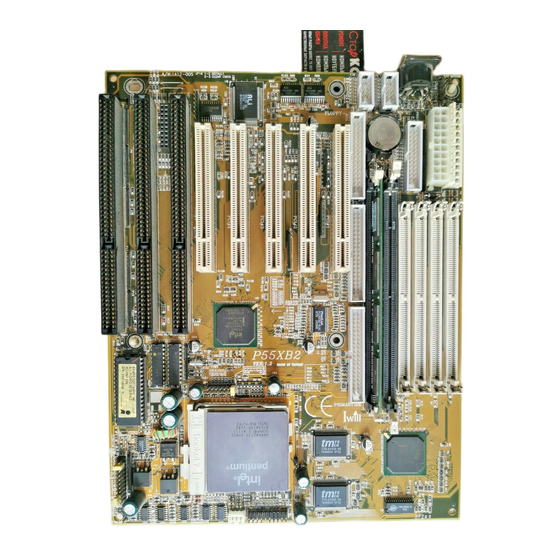
HAPTER 0 Quick Installation Several easy installation steps will be described in this chapter to help the experienced users for quick installation. If you are new user and need to know more about this motherboard, please start from Chapter 1. - Page 7 S. 1 S. 2 S. IDE P. IDE BIOS P. Control Figure 1:Connectors for P55XB2...
- Page 8 JP16 JP15 Figure 2 : Jumpers location...
- Page 9 Connector Function Description 20 pin Standard ATX power input connector 12 pin Standard AT power input connector Bank 1, each bank consist by two SIMM Socket(Single In-line Memory Module ) Bank 2, each bank consist by two SIMM Socket(Single In-line Memory Module ) BIOS BIOS (Basic Input Output System)
- Page 10 Jumper Setting CPU Voltage Select CPU Frequency select CPU Voltage Monitor Jumper JP16 CMOS Clear Jumper JP15 Remote power switch for ATX Power Manufacture Default Setting CPU Clock CPU Clock at 166Mhz CPU Voltage CPU Voltage at Auto Setting Cache Size 512K Pipelined Burst Cache on board Printer Port DMA3 for ECP Mode, Address=378h at IRQ7...
- Page 11 Quick Installation Step 1. Install CPU Pull up the CPU handle bar, place the CPU into the socket in gentle/ horizontal way then pull down the handle bar back to its original place. Care must be taken for the CPU’s direction when was inserted. Step 2.
- Page 12 All Intel Dual Voltage ( P55C, 166 / 200 / 233Mhz ) CPU set to 2.83V. AMD Dual Voltage ( K6, 166 / 200Mhz ) CPU set to 2.9V AMD Dual Voltage ( K6, 233Mhz ) CPU set to 3.2V Cyrix Dual Voltage ( M2, 166 / 200 Mhz ) CPU set to 2.83V 3.52 V 3.38...
- Page 13 Step 4. Adjust the CPU Frequency The manufacture default at 166Mhz with the special design on this motherboard. Once the jumper cap was inserted, it will automatically caculate the Internal/ External Clock and CLKMUL (Clock Multiplier). Just insert the jumper cap to the CPU real frequency. There are more detail description on Chapter 3.3.3 CPU Clock Select and Appendix A CPU for more information.
- Page 14 Bank 1 Bank 0 DIMM 1= Bank 1 DIMM 0= Bank 0 Step 6. Install the Internal Peripherals The internal peripherals means devices that in the computer chassis like the Floppy Disk Drive, Hard Disk Drive, CD ROM Drive …etc. With this motherboard package, there are 34, 40, pin flat cable.
- Page 15 Sub male connector cable are for Serial port, one 26 pin convert to 25 pin D- Sub female connector cable is for Parallel port, one 5 pin housing but 4 wires into a 6 pin Mini-DIN is for the PS/2 mouse. Step 8.
- Page 16 Step 11. Connect the Speaker Connect the speaker to the motherboard’s speaker connector. (Normally the red cable is +5V power) (Reference to the Chapter 3—Hardware Installation for detail pin assignment) Step 12. Connect the Power LED Most computer chassis provides a power LED for identify if the system is on or off.
- Page 17 Step 16. Connect the Keyboard Follow the keyboard cable’s key direction and connect to this motherboard.
- Page 18 Step 17. Plug the Display Card Finally, follow the display card you have and insert in horizontal direction into the PCI/ISA expansion slot. Step 18. Power on the system Once the system was power on, on the lower left corner of the screen will show ”Press DEL to enter SETUP, ESC to skip memory test”.
-
Page 19: Features
1.1 Featuress This P55XB2 Ultra DMA 33 motherboard is your best choice for optimized media rich performance desktop on the Pentium® level processor with the new MMX™ technology. It incorported with Intel’s 430TX PCIset with I/O subsystem that... - Page 20 AT form factor can not achieved. This P55XB2 Ultra DMA 33 Motherboard is designed to fit into standard AT form factor based computer case. It is a powerful combination of performance, quality and innovative design to address the need of today’s market.
- Page 21 3 X 16-bits ISA slots, 5 X 32-bits PCI slots Switching DC/DC Voltage Regulator for CPU: Effeciently cool down CPU temperature, increase system stability and supoport future processors…………. The more and more Pentium or compatible processor is releasesing and most of them are not using the same voltage for the processor.
- Page 22 Two onboard 10 pin box-header connector provide 2 Serial port. Use the two cables that goes with this motherboard to convert to the standard 9 and 25 pins D-Sub connectors. Two high speed 16550 UART serial port IRQ selectable from BIOS. Address changeable form system BIOS NS16C550 compatible, Programmable Baud Rate Generator Parallel Port...
-
Page 23: Preparation And Inspection
Hardware Installation 2.1 Preparation and Inspection This P55XB2 Ultra DMA 33 Motherboard, like all electronic equipment is static sensitive. Please take the proper precautions when handling this board. You should avoid static up. If possible, You should ground yourself by touching a metal table or your computer frame. -
Page 24: Placement
2.2 Placement S. 1 S. 2 S. IDE P. IDE BIOS P. Control Figure 1:Connectors for P55XB2... - Page 25 JP16 JP15 Figure 2 : Jumpers for P55XB2...
-
Page 26: Cpu Group
2.3 CPU group 2.3.1 CPU Socket This CPU socket provides flexibility for Intel Pentium , Pentium OverDrive, Pentium future processors, AMD K5(5k86) and Cyrix M1(6x86) processor. When installing the CPU into the Zero Insertion Force ( ZIF ) socket should be very carefully. - Page 27 2.3.2 JP6 CPU Cooler Fan Power Connector Warning !!! Warning !!! Warning !!! CPU Cooler is required to be placed on top of the CPU all the times to prevent CPU over-heat. The CPU fan power is a 1 x 3 pin connector. +12V Control Metal Latch...
- Page 28 put the colored yellow jumper cap to the speed your CPU really is (the CPU internal/external clock ratio and ISA clock will be automatically selected by setup the JP7) Cyrix Cyrix Following figure are for reference: Intel CPU Cyrix Cyrix Cyrix CPU at 133 MHz CPU at 200 MHz...
- Page 29 Cyrix Cyrix Cyrix Cyrix 6x86-P120+ Cyrix 6x86-P133+ Cyrix 6x86-P150+ CPU at 100 MHz CPU at 110 MHz CPU at 120 MHz Cyrix Cyrix Cyrix 6x86-P166+ Cyrix 6x86-P200+ CPU at 133 MHz CPU is 150 MHz AMD CPU (K5,K6) Cyrix Cyrix Cyrix AMD-K5-PR75 AMD-K5-PR90...
- Page 30 Cyrix Cyrix Cyrix Cyrix AMD-K5-PR120 AMD-K5-PR133 AMD-K5-PR150 AMD-K5-PR160 CPU at 90 MHz CPU at 100 MHz CPU at 120 MHz CPU at 133 MHz Reference to Appendix A for CPU voltage setting detail. 2.3.4 CPU Voltage (JP4) The manufacture default is “Auto”. This jumper set the voltage for the CPU. For example, the Intel Pentium P54 CPU uses 3.38V(STD)or 3.52V (VRE).
-
Page 31: D-Ram Configuration P28
The Pentium with MMX , AMD K6 and Cyrix M2 is a dual voltage CPU. one volatge for CPU Core (Vcore), another for CPU input/output single (Vio). The JP3 pin1 is connected to the CPU Vcore and pin2 is connected to the CPU Vio. The motherboard auto voltage function should work with most Processor. - Page 32 Four SIMM socket (Bank 0, Bank 1)—support Fast Page and EDO DRAM. These four SIMM sockets devide into two Bank by each two SIMM socket. Each two SIMM in the same Bank must be the same memory size and type, the Fast Page and EDO DRAM can not be in the same Bank. Reference to the following installation possibility that user might install.
- Page 33 Bank 1 Bank2 Bank1 Bank 0 Install the SIMM Install the DIMM Left Key Zone Center Key Zone (Unbuffered) (3.3V DRAM)
-
Page 34: Ide Interface
NOTE: The 70 ns Fast Page Mode or 60 ns EDO DRAM is recommended. DIMM specification: 3.3V/ Unbuffered, this motherboard will not supports the 5V or Buffered DIMM. This motherboard supports 4 Clock for each DIMM Socket 2.6 IDE Interface 2.6.1 Primary, Secondary IDE Connectors Primary / Secondary IDE are 40 pins internal IDE port connectors. -
Page 35: Usb
3.6.2 IDE LED SPEAKER PWR ON LED KEYLOCK A 2 pins IDE detect LED connector. Assignment LED anode (+) LED cathode (-) 2.7 USB (Universal Serial Bus) Basically the USB is suitable for middle low speed devices like Mouse, Keyboard, Joystick..etc. -
Page 36: Enhanced Multi-Io
SIDE USB Riser Card 2.8 Enhanced Multi-IO 2.8.1 FDC Connector The IBM compatible floppy disk drive has 360KB, 720KB, 1.2KB, 1.44KB and 2.88KB. The most popular is 1.44MB in 3.5 inch. There is also one kind of 2.88MB FDD used in the Japan NEC PC98 series computer. This motherboard can support for up to two different kind FDD in same connector and also support QIC-80 Tape Driver under floppy interface. - Page 37 Parallel port is a 25 pins female external DB25 connector for parallel port. Parallel...
- Page 38 Following selection is all controled by the BIOS: ECP Mode DMA Channel Select by BIOS printer Port Address and IRQ Select by BIOS (378h/3BC with IRQ7, 278h with IRQ5.) Printer and IEEE 1284 cable The IEEE 1284 compliant cables have better features on the following: Twisted pairs of conductors Full foil shield Wire braid...
- Page 39 2.9 Others 2.9.1 Keyboard Connector The keyboard connector is a 5-pin, circular-type Mini-DIN socket. It is used to connect this SCSImotherboard keyboard interface to any standard AT- compatible keyboard (84 or 101key type keyboards). The pin assignment are as follows: Keyboard 2.9.2 Power Supply Connector There are two types of power connector provided by this SCSI motherboard.
- Page 40 Power connector Power connector Orange 3.3 V 3.3 V 5.0 V -12.0 V Yellow 12.0 V Blue -12.0 V PS-ON 5.0 V Black Black Black 5.0 V Black White -5.0 V - 5.0 V PW-OK 5.0 V 5.0 V 5VSB 5.0 V 12.0 V 5.0 V...
- Page 41 Reset IDE SMI PWR Speaker Keylock Lock SPKR Note : The Power LED can be connected from both the “LED” & “Keylock”. This motherbaord has no Turbo function, it will not support Turbo function. If the computer chassis has the front Turbo LED in the front panel for identificationThe Power LED will light-on when you connect a computer case that mounted Turbo LED and power on this system.
- Page 42 Infrared The IR (Infrared) port is a 7 pin pin-header connector, this connector is reserved for future use.
- Page 43 2.9.6 CMOS Clear Jumper JP16 The JP16 is a 3 pin pin-header connector, jumper cap on 1-2 for normal operation or jumper cap on 2-3 for clear CMOS. 2.9.7 ATX Power Control JP15 The JP15 is a 2 pin pin-header connector, it must be connected to a switch when the ATX Power Supply is used.
-
Page 44: Chapter 3- Award Bios Setup P38
HAPTER 3 Award BIOS Setup Notice The information in this manual is subject to change without notice. The software described in this guide is furnished under a license agreement and may be used or copied only in accordance with the terms of the agreement. Award Software, Inc. - Page 45 The rest of this manual is intended to guide you through the process of configuring your system using Setup.
- Page 46 Starting Setup The Award BIOS is immediately activated when you first power on the computer. The BIOS reads the system information contained in the CMOS and begins the process of checking out the system and configuring it. When it finishes, the BIOS will seek an operating system on one of the disks and then launch and turn control over to the operating system.
- Page 47 Esc key Main Menu -- Quit and not save changes into CMOS Status Page Setup Menu and Option Page Setup Menu -- Exit current page and return to Main Menu PgUp key Increase the numeric value or make changes PgDn key Decrease the numeric value or make changes + key Increase the numeric value or make changes...
- Page 48 manufacturer to provide the absolute maximum performance and reliability. Even a seemingly small change to the chipset setup has the potential for causing you to use the override.
- Page 49 3.1 Main Menu Once you enter the Award BIOS CMOS Setup Utility, the Main Menu will appear on the screen. The Main Menu allows you to select from several setup functions and two exit choices. Use the arrow keys to select among the items and press <Enter> to accept and enter the sub-menu.
- Page 50 Super / User Password Setting Change, set, or disable password. It allows you to limit access to the system and Setup, or just to Setup. Chipset Features Setup This setup page includes all the items of chipset special features. Power Management Setup This entry only appears if your system supports Power Management, screen PC”, standards.
- Page 51 IDE HDD Auto Detection Automatically detect and configure hard disk parameters. The Award BIOS includes this ability in the event you are uncertain of your hard disk parameters. HDD Low Level Format If supported by your system, this provides a hard disk low level format utility.
-
Page 52: Standard Cmos Setup
3.2 Standard CMOS Setup The items in Standard CMOS Setup Menu are divided into 10 categories. Each category includes no, one or more than one setup items. Use the arrow keys to highlight the item and then use the <PgUp> or <PgDn> keys to select the value you want in each item. - Page 53 The time format is <hour> <minute> <second>. The time is calculated based on the 24-hour military-time clock. For example, 1 p.m. is 13:00:00.
- Page 54 Daylight saving The category adds one hour to the clock when daylight-saving time begins. It also subtracts one hour when standard time returns. Enabled Enable daylight-saving Disabled Disable daylight-saving Primary Master/ Primary Slave/ Secondary Master/ Secondary Slave The categories identify the types of 2 channels that have been installed in the computer.
- Page 55 SECTORS number of sectors MODE mode type Drive A Type / Drive B Type If a hard disk has not been installed Select NONE and press <Enter>. The category identifies the types of floppy disk drive A or drive B that have been installed in the computer.
- Page 56 The category determines whether the computer will stop if an error is detected during power up.
- Page 57 No errors Whenever the BIOS detects a non-fatal error the system will be stopped and you will be prompted. All errors The system boot will not be stopped for any error that may be detected. All, The system boot will not stop for a keyboard error; it But Keyboard will stop for all other errors.
-
Page 58: Bios Features Setup
3.3 BIOS Features Setup This section allows you to configure your system for basic operation. You have the opportunity to select the system default speed, boot-up sequence, keyboard operation, shadowing and security. ROM PCI/ISA BIOS (XXXXXXXX) BIOS FEATURES SETUP AWARD SOFTWARE, INC. Virus Warning Disabled Video BIOS Shadow... - Page 59 Enabled Activates automatically when the system boots up causing a warning message to appear when anything attempts to access the boot sector or hard disk partition table. Disabled No warning message will appear when anything attempts to access the boot sector or hard disk partition table. NOTE: Many disk diagnostic programs which attempt to access the boot sector table can cause the above warning message.
- Page 60 C,CDROM, A System will first search for hard disk drive , then CDROM drive, and then floppy disk drive. Swap Floppy Drive This item allows you to determine whether enable the swap floppy drive or not. The choice: Enabled/Disabled. Boot Up Floppy Seek During POST, BIOS will determine if the floppy disk drive installed is 40 or 80 tracks.
- Page 61 Set the speed to low Gate A20 Option This entry allows you to select how the gate A20 is handled. The gate A20 is a device used to address memory above 1 Mbytes. Initially, the gate A20 was handled via a pin on the keyboard. Today, while keyboards still provide this support, it is more common, and much faster, for the system chipset to provide support for gate A20.
- Page 62 24 characters per second 30 characters per second Typematic Delay (Msec) When the typematic rate is enabled, this selection allows you to select the delay between when the key was first depressed and when the acceleration begins.
- Page 63 250 msec 500 msec 750 msec 1000 1000 msec Security Option This category allows you to limit access to the system and Setup, or just to Setup. System The system will not boot and access to Setup will be denied if the correct password is not entered at the prompt.
- Page 64 RAM. However, it is optional depending on chipset design. Video Shadow will increase the video speed.
- Page 65 Enabled Video shadow is enabled Disabled Video shadow is disabled C8000 - CBFFF DC000 - DFFFF These categories determine whether option ROMs will be copied to RAM. An example of such option ROM would be support of on- board SCSI. Enabled Optional shadow is enabled Disabled...
- Page 66 should never need to be altered. The default settings have been chosen because they provide the best operating conditions for your system. The only time you might consider making any changes would be if you discovered that data was being lost while using your system.
- Page 67 DRAM Settings The first chipset settings deal with CPU access to dynamic random access memory (DRAM). The default timings have been carefully chosen and should only be altered if data is being lost. Such a scenario might well occur if your system had mixed speed DRAM chips installed so that greater delays may be required to preserve the integrity of the data held in the slower memory chips.
- Page 68 DRAM R/W Leadoff Timing This sets the number of CPU clocks allowed before reads and writes to DRAM are performed. Seven clocks leadoff for reads and six clocks leadoff for writes. Six clocks leadoff for reads and five clocks leadoff for writes. 7/6 Leadoff timing is the default.
- Page 69 DRAM Write Burst Timing This sets the timing for burst mode writes from DRAM. Burst read and write requests are generated by the CPU in four separate parts. The first part provides the location within the DRAM where the read or write is to take place while the remaining three parts provide the actual data.
- Page 70 Turn-Around Insertion When this is enabled, the chipset will insert one extra clock to the turn-around of back-to-back DRAM cycles. Disabled is the default. ISA Clock This item allows you to select the PCI clock type. PCI CLK/3 PCI clock type PCI CLK/4 PCI clock type Cache Features...
- Page 71 PCI and IDE Configuration Bit I/O Recovery Time The recovery time is the length of time, measured in CPU clocks, which the system will delay after the completion of an input/output request. This delay takes place because the CPU is operating so much faster than the input/output bus that the CPU must be delayed to allow for the completion of the I/O.
- Page 72 Chipset Special Features When disabled, the chipset behaves as if it were the earlier DRAM ECC/PARITY Select This item allows you to select between two methods of DRAM error checking, ECC and Parity (default). Memory Parity / ECC Check This item allows you to select between three methods of memory error checking, Auto, Enabled and Disabled Single Bit Error Report L2 Cache Cacheable...
-
Page 73: Power Management Setup
Pipeline Cache Timing This item allows you to select two timing of pipeline cache, Faster and Fastest. 3.5 Power Management Setup The Power Management Setup allows you to configure you system to most effectively save energy while operating in a manner consistent with your own style of computer use. - Page 74 Doze Mode Standby Mode Suspend Mode HDD Power Down There are four selections for Power Management, three of which have fixed mode settings. Disable (default) No power management. Disables all four modes Min. Power Saving Minimum power management. Doze Mode = 1 hr. Standby Mode = 1 hr., Suspend Mode = 1 hr., and HDD Power Down = 15 min.
- Page 75 PM Timers The following four modes are Green PC power saving functions which are only user configurable when User Defined Power Management has been selected. See above for available selections. Doze Mode When enabled and after the set time of system inactivity, the CPU clock will run at slower speed while all other devices still operate at full speed.
- Page 76 When set On, activity will neither prevent the system from going into a power management mode nor awaken it.
- Page 77 • IRQ3 (COM 2 ) • IRQ4 (COM 1) • IRQ5 (LPT 2) • IRQ6 (Floppy Disk) • IRQ7 (LPT 1) • IRQ8 (RTC Alarm) • IRQ9 (IRQ2 Redir) • IRQ10 (Reserved) • IRQ11 (Reserved) • IRQ12 (Reserved) • IRQ13 (Coprocessor) •...
-
Page 78: Pnp/Pci Configuration
3.6 PnP/ PCI Configuration Setup This section describes configuring the PCI bus system. PCI, or Personal Computer Interconnect, is a system which allows I/O devices to operate at speeds nearing the speed the CPU itself uses when communicating with its own special components. This section covers some very technical items and it is strongly recommended that only experienced users should make any changes to the default settings. - Page 79 Reset Configuration Data This item allows you to determine reset the configuration data or not. Choices are Enabled and Disabled (default). IRQ3/4/5/7/9/10/11/12/1 4/15, DMA0/1/3/5/6/7 assigned to This item allows you to determine the IRQ / DMA assigned to the ISA bus and is not available to any PCI slot.
- Page 80 Remember that this setting refers to the hard disk drive itself, rather than individual partitions. Since each IDE controller supports two separate hard drives, you can select the INT# for each. Again, you will note that the primary has a lower interrupt than the secondary as described in ...
-
Page 81: Integrated Peripherals
3.7 Integrated Peripherals ROM PCI/ISA BIOS (XXXXXXXX) INTEGRATED PERIPHERALS AWARD SOFTWARE, INC. IDE HDD Block Mode Enabled IDE Primary Master PIO Auto IDE Primary Slave PIO Auto IDE Secondary Master PIO Auto IDE Secondary Slave PIO Auto On-Chip Primary PCI IDE Enabled On-Chip Secondary PCI IDE Enabled... - Page 82 Disabled No IDE controller occupying a PCI slot. Disabled is the default. IDE PIO IDE hard drive controllers can support up to two separate hard drives. These drives have a master/slave relationship which are determined by the cabling configuration used to attach them to the controller. Your system supports two IDE controllers--a primary and a secondary--so you have to ability to install up to four separate hard disks.
- Page 83 On-Chip Secondary PCI IDE As above for the Primary controller, this setup item you either to enable or disable the secondary controller. You might choose to disable the controller if you were to add a higher performance or specialized controller.
-
Page 84: Load Setup Defaults
Enabled Primary HDD controller used Disabled Primary HDD controller not used. Enabled is the default. 3.8 LOAD SETUP DEFAULTS The chipset defaults are settings which provide for maximum system performance. While Award has designed the custom BIOS to maximize performance, the manufacturer has the right to change these defaults to meet their needs. -
Page 85: Supervisor/User Password
3.9 Supervisor/User Password Setting ROM PCI/ISA BIOS (XXXXXXXX) CMOS SETUP UTILITY AWARD SOFTWARE, INC. STANDARD CMOS SETUP SUPERVISOR PASSWORD BIOS FEATURES SETUP USER PASSWORD CHIPSET FEATURES SETUP IDE HDD AUTO DETECTION POWER MANAGEMENT SETUP HDD LOW LEVEL FORMAT PNP/ PCI CONFIGURATIONI/O SETUP Enter Password : SAVE &... -
Page 86: Ide Hdd Auto Detection
When a password has been enabled, you will be prompted to enter it every time you try to enter Setup. This prevents an unauthorized person from changing any part of your system configuration. Additionally, when a password is enabled, you can also require the BIOS to request a password every time your system is rebooted. - Page 87 Appendix A—CPU Confluence Intel CPU CPU Spec. Internal Clk Voltage Pentium 75 Full Series 75Mhz 3.38V Pentium 90 Full Series 90Mhz 3.38V Pentium 100 SY046 100Mhz 3.1V Pentium 100 Q0563,Q0587,Q0614 100Mhz 3.38V SX886,SX910,Q0656 Q0657,Q0697,SX963 SZ996,SU032,Q0853 SK124,Q0784,SY007 SU110,SU099 Pentium 100 Q0677,SX960,Q0658 100Mhz 3.52V SX962,Q0698,SX970...
- Page 88 MMX 200...
- Page 89 AMD CPU There are three kinds of AMD CPU available in present market.(5k86 SSA/5, K5 and K6). The printing on these CPUs are: AMD5k86-P90 AMD-SSA/5-90Abxxx AMD-K5-PR100ABxxx AMD-K6/PR2-xxx The printing on SSA/5 5k86 CPU is AMD 5k86-P90 AMD-SSA/5-90Abxxx The value behind the AMD5k86 is the processor speed. The value behind the SSA/5 is the internal clock (for example 90).
- Page 90 The printing on the K6 CPU is: AMD-K6/PR2-xxx The value behind the K6 is the processor speed. The CPU jumper should adjust to the same position as your CPU really is. The CPU working voltage is: AMD-K6/PR2-166: 2.9V AMD-K6/PR2-200:2.9V AMD-K6/PR2-233:3.2V...
- Page 91 Cyrix CPU The Cyrix CPU’s printing is: 6x86-P166+GP 133Mhz 3.52V (028) The first lineP166 processor index. The second line is internal clock. (for example P133 is 133 Mega Hertz) The J15 should adjust to the same value as the CPU really are. The third line is CPU working voltage index.
Need help?
Do you have a question about the P55XB2 and is the answer not in the manual?
Questions and answers