Table of Contents
Advertisement
Quick Links
EC Declaration of Conformity
We
Iwill Corp.
No. 9-1, Kong 6th RD.,
Lin Kou 2nd Industrial
Park, Taipei, Taiwan R.O.C.
declare under sole responsibility that the
P55XU/XUW motherboard
meets the intent of Directive 89/336/ECC for Electromagnetic Compatibility.
Compliance was demonstrated to the following specifications as listed in the
official Journal of the European Communities:
EN 50081-1 Emissions:
EN 55022
EN 55022
EN 60555-2 Power Harmonics
EN 50082-1 Immunity:
IEC
801-2 Electrostatic Discharge
IEC
801-3 RF Radiat
IEC
801-4 Fast Transient
Radiated, Class B
Conducted, Class B
1
Advertisement
Table of Contents

Related Manuals for IWILL P55XU


Summary of Contents for IWILL P55XU
- Page 1 Lin Kou 2nd Industrial Park, Taipei, Taiwan R.O.C. declare under sole responsibility that the P55XU/XUW motherboard meets the intent of Directive 89/336/ECC for Electromagnetic Compatibility. Compliance was demonstrated to the following specifications as listed in the official Journal of the European Communities:...
- Page 2 About This Manual This manual will guide the user how this SCSI motherboard was consisted. All useful information will be described in later chapters. Keep this manual for your future upgrade or system configuration changed. The chapter Quick Installation --- This chapter’s description is suitable for most user, Just follow step by step in installing the system.
-
Page 3: Table Of Contents
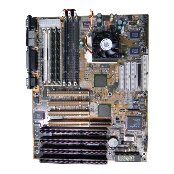
Contents Chapter 0- Quick Installation Chapter 1- Overview 1.1 Features 1.2 Specif ications Chapter 2- Quick Installation Chapter 3- Hardware Installation 3.1 Preparation and Inspection 3.2 Placement 3.3 CPU group 3.4 Cache Memory 3.5 D-RAM Conf iguration 3.6 SCSI Interf ace 3.7 RAIDBUS 3.8 IDE Interf ace 3.9 USB... - Page 5 If you are new user and need to know more about this motherboard, please start from Chapter 1. ATX P. Socket 7 JP11 BIOS P. IDE S. IDE P.Control JP25 U. SCSI Figure 1:Connectors for P55XU...
- Page 6 Socket 7 RAID W. SCSI Figure 2 : Connectors for P55XUW only Socket 7 JP10 C200+ JP23 3.52 3.38 JP26 2.83 JP25 AUTO Figure 3 : Jumpers location...
- Page 7 Connector Function Description ATX P. 20 pin Standard ATX power input connector BIOS BIOS (Basic Input Output System) 321 pin Socket 7 CPU socket DIMM1 (Dual In-line Memory Module ) Bank 2 DIMM2 (Dual In-line Memory Module ) Bank 1 DIMM3 (Dual In-line Memory Module ) Bank 0 34 pin Floppy Disk Drive with key protect connector 25 pin Parallel D-Sub connector...
- Page 8 Jumper Setting J19/J21 BIOS Mode select Reserved for manufacture use SCSI port Enabled/ Disabled select JP10 CPU clock select JP23 CPU working voltage select JP25 Remote power switch JP26 CMOS clear select Quick Installation Step 1. Install CPU Pull up the CPU handle bar, place the CPU into the socket in gentle/ horizontal way then pull down the handle bar back to its original place.
- Page 9 Step 2. Install CPU Cooler Hook the CPU Cooler’s metal latch one side to the CPU socket’s peg, then press the metal latch again to fit into another side. Warning: Care must be taken when the CPU Cooler was installed, if not a suitable force might scrach this motherboard.
- Page 10 Step 3. Adjust the CPU voltage (default is “3.52V”) This motherboard is shipped with CPU voltuage default at “3.52V”, is for most Intel Pentium P54C processor, with this manufacture default voltuage will working with all of Intel Pentium or compatible processor. Or reference to the Appendix A—CPU for more information Step 4.
- Page 11 Socket 7 JP10 Step 5. Install the Memory Module For at least two pieces 72 pin SIMM(Single In-line Memory Module) or one piece 168 pin DIMM(Dual In-line Memory Module)must inserted in this 64 bit Pentium base motherboard. The J18, J19 were combined as Bank0, the same Bank0 address is DIMM1.
- Page 12 Step 7. Install the External Peripherals The external device means devices that outside the computer chassis like the Serial mouse, Printer, PS/2 Mouse, External Modem…etc. Step 8. Install the Reset switch Most computer chassis provides a reset switch to front pannel control.
- Page 13 Step 10. Install the Keylock Most computer chassis will provides a keylock switch. Normally connect the marked keylock connector to the motherboard keylock. This will cause the keyboard out of function once you switch the keylock to “Lock”. This will prevent any un-authorized keyin.
- Page 14 Follow the keyboard cable’s key direction and connect to this motherboard. Step 16. Install the Display Card Finally, follow the display card you have and insert in horizontal direction into the PCI/ISA expansion slot. Step 17. Power on the system Once the system was power on, on the lower left corner of the screen will show ”Press DEL to enter SETUP, ESC to skip memory test”.
-
Page 15: Chapter 1- Overview
Keep this, for your future need. 1.1 Featuress This P55XU/XUW SCSI Motherboard is the newest ATX form factor based member to our SCSI Motherboard solution products families. It incorporated with Intel 6... - Page 16 2 Mega bit Award BIOS, supports bootable CD-ROM, bootable SCSI harddisk, USB,on-screen "Plug & Play" setup for Adaptec SCSI, Enhanced IDE, and Ultra Multi-IO. Support Flash ROM ( This ROM provides better upgrade ability for user to update their BIOS data on the system board, user ca n down-load/ update newer version BIOS from Internet or diskette file.
- Page 17 Ultra/ Ultra Wide SCSI interface: ◼ P55XU equipe with Adaptec PCI Ultra SCSI ( AIC-7860 chip ) built in which is equilevent to Adaptec AHA-2940AU PCI SCSI controller. Data transfer rate up to 20MB/Sec. ...
-
Page 18: Specifications
◼ Floppy Interface : Support both 3 1/2" and 5 1/4" floppy disk drives and Tape Drive (360K / 720K/ 1.2M / 1.44M / 2.88MB) Enabled/Disable selectable from system BIOS Non-Burst Mode DMA Option,16 Byte Data FIFO ... - Page 19 HAPTER 2 Quick Installation This SCSI Motherboard is shipped with manufacture preset at : CPU Clock at 166 MHz Adaptec SCSI Chip Enabled Adaptec Wide SCSI Mode Enabled (P55XUW only) SCSI Terminator Control by BIOS 512K Pipeline Burst Cache on board Printer ECP Mode at DMA3 Printer at IRQ7 , Address at 378h Serial 1 at IRQ4, Serial 2 at IRQ3...
-
Page 20: Chapter 3- Hardware Installation
Hardware Installation 3.1 Preparation and Inspection This P55XU/XUW SCSI Motherboard, like all electronic equipment is static sensitive. Please take the proper precautions when handling this board. You should avoid static up. If possible, You should ground yourself by touching a metal table or your computer frame. -
Page 21: Placement
3.2 Placement ATX P. Socket 7 JP11 BIOS P. IDE S. IDE P.Control JP25 U. SCSI Figure 1:Connectors for P55XU Socket 7 RAID W. SCSI Figure 2 : Connectors for P55XUW... - Page 22 Socket 7 JP10 C200+ JP23 3.52 3.38 JP26 2.83 JP25 AUTO Figure 3 : Jumpers location...
-
Page 23: Cpu Group
3.3 CPU group 3.3.1 CPU Socket This CPU socket provides flexibility for Intel Pentium , Pentium OverDrive, Pentium future processors, AMD K5(5k86) and Cyrix M1(6x86) processor. When installing the CPU into the Zero Insertion Force ( ZIF ) socket should be very carefully. Lift the handle bar of this 321 Pin ZIF socket up carefully and insert the CPU into ZIF socket. - Page 24 CPU really is (the CPU internal/external clock ratio and ISA clock will be automatically selected by setup the JP10) The marked “T75” and “RSV” jumper address in the JP10 is special engineer purpose. Ratio Bus Frequency Jumper Remark Intel 120MHz 60 MHz Intel 150MHz 60 MHz...
- Page 25 Cyrix CPU AMD CPU (K5, K6)
- Page 26 Reference to Appendix A for CPU voltage setting detail. 3.3.4 CPU Voltage(JP23) The default “3.52V” is for Intel P54C. This motherboard will detect the CPU working voltage automatically, if you put the jumper on the “Auto” address. For the future new processor comes out later than this motherboard’s design that did not include the new processor’s working voltage, then check the processor vendor for correct jumper setting.
-
Page 27: D-Ram Conf Iguration P24
3-5 D-RAM Configuration This motherboard provides four (4) SIMM module (Single In -Line Memory Module) and three (3) DIMM (Dual In-Line Memory Module) for memory expansion. These expansion memory sockets devided into three (3) memory bank. For at least two pieces 72 pin SIMM or one piece 168 pin DIMM must inserted in this 64 bit Pentium base motherboard. - Page 28 Center Key Zone (Unbuffered) (3.3V DRAM) The P55XU/XUW supports different type of system memory. It will auto detect the memory size, no jumper needed for this function or configure. NOTE: 1 . P55XU/XUW supports both Fast Page DRAM or EDO DRAM SIMM/DIMMs,but they cannot be mixed within the same memory bank.
-
Page 29: Scsi Interface
15 devices. And perform the 40MB/Sec transfer speed by this Ultra Wide SCSI. P55XU-- is a narrow SCSI and use the 8 bit Bus, this can connect the maximum 7 devices. And perform the 20MB/Sec transfer speed by this Ultra SCSI. - Page 30 3.6.2 Ultra SCSI Connector U. SCSI is a 50 pins 16 bit Ultra SCSI connector. It attaches the SCSI cable(s) from the P55XU/XUW SCSI controller to the SCSI peripherals. The external SCSI port expansion kit is a optional for your connecting external devices.
- Page 31 For linking both the 50 & 68 pin SCSI together, the High byte terminator must set to on and Low byte set to off. 3.6.4 Link Internal & External SCSI devices The concept of linking the internal and external SCSI devices is still the same--- cabled together in a single, connected series.
- Page 32 3.6.5 Set SCSI IDs You must assign a different SCSI ID to each device on the SCSI bus connected to this motherboard. See your SCSI device documentation for directions on how to determine the ID and change it. ◼ Ultra/ Fast SCSI devices that connect to this mainboard's SCSI connector can be assigned ID from 0 to 7.
-
Page 34: Ide Interface
3.7 RAIDBUS slot (P55XUW only) 3.7.1 SCSI RAIDPort Turn this SCSI embedded motherboard to be hardware assist RAID ready by adding the RAIDBUS 1130 adapter. This RAIDBUS slot by adding the RAIDBUS 1130 adapter can support : ◼ Bus Master DMA ◼... -
Page 35: Usb
Socket 7 3.8.2 IDE LED Socket 7 A 2 pins IDE detect LED connector. 3.9 USB (Universal Serial Bus) Basically the USB is suitable for middle low speed devices like Mouse, Keyboard, Joystick..etc. In before, all these were using different connectors, and it is complicated for end user in installing the system. - Page 36 Socket 7...
-
Page 37: Enhanced Multi-Io
3.10 Enhanced Multi-IO 3.10.1 FDC Connector The IBM compatible floppy disk drive has 360KB, 720KB, 1.2KB, 1.44KB and 2.88KB. The most popular is 1.44MB in 3.5 inch. There is also one kind of 2.88MB FDD is using on the Japan NEC PC98 series computer. -
Page 38: Other
Printer and IEEE 1284 cable The IEEE 1284 compliant cables have better features on the following: Twisted pairs of conductors Full foil shield Wire braid Controlled impedance -- 62 ohm Limited cross-walk With these features will guarantee the IEEE 1284 cable perform at much higher bandwidth rates that the fast Centronics, EPP and ECP modes perform at. - Page 39 Socket 7 3.11.2 Power Supply Connector The 20 pin box header is ATX standard power connector. (will describe this on next chaptor ATX Form Factor). 3.11.3 Reset, SCSI LED, IDE LED, SMI Switch, LED, Speaker, KeylockConnectors Socket 7 Note : This motherboard has no Turbo function, it will not support Turbo function.
- Page 40 Socket 7 JP26 JP26 Function Note Normal operation *Default CMOS clear 3.11.5 PS/2 Mouse Socket 7 PS/2 Mosuse is a 6 pin Mini-DIN PS/2 mouse connector, the manufacture default is IRQ12.
-
Page 41: Chapter 4- Atx Form-Factor Overview
HAPTER 4 ATX Form-Factor Overview The P55XU/XUW has been designed with ATX form -factor. The board size is 12" x 9.6" (305mm x 245mm). The ATX form-factor improves over Baby AT and LPX in a number of ways. By using the ATX chassis then the power supply... - Page 42 ON/OFF switch. The system power ON/OFF button should be a momentary Switch or togle switch. The P55XU/XUW has been designed with "soft off" functions. You can turn OFF the system from one of two sources: One is the front panel power ON/OFF switch, and the other is "Soft off"...
- Page 43 ATX Power Supply Connector : Single Name Single Name 3.3V 3.3V -12.0V 3.3V PS-ON 5.0V 5.0V -5.0V PW-OK 5.0V 5VSB 5.0V 12.0V...
-
Page 44: Chapter 5 Award Bios Setup
HAPTER 5 Award BIOS Setup Notice The information in this manual is subject to change without notice. The software described in this guide is furnished under a license agreement and may be used or copied only in accordance with the terms of the agreement. Award Software, Inc. - Page 45 Starting Setup The Award BIOS is immediately activated when you first power on the computer. The BIOS reads the system information contained in the CMOS and begins the process of checking out the system and configuring it. When it finishes, the BIOS will seek an operating system on one of the disks and then launch and turn control over to the operating system.
- Page 46 - key Decrease the numeric value or make changes F1 key General help, only for Status Page Setup Menu and Option Page Setup Menu (Shift)F2 key Change color from total 16 colors. F2 to select color forward , (Shift) F2 to select color backward F3 key Calendar, only for Status Page Setup Menu F4 key...
- Page 47 5.1 Main Menu Once you enter the Award BIOS CMOS Setup Utility, the Main Menu will appear on the screen. The Main Menu allows you to select from several setup functions and two exit choices. Use the arrow keys to select among the items and press <Enter>...
- Page 48 Super / User Password Setting Change, set, or disable password. It allows you to limit access to the system and Setup, or just to Setup. Chipset Features Setup This setup page includes all the items of chipset special features. Power Management Setup This entry only appears if your system supports Power Management, screen PC”, standards.
- Page 49 Automatically detect and configure hard disk parameters. The Award BIOS includes this ability in the event you are uncertain of your hard disk parameters. HDD Low Level Format If supported by your system, this provides a hard disk low level format utility. Save &...
-
Page 50: Standard Cmos Setup
5.2 Standard CMOS Setup The items in Standard CMOS Setup Menu are divided into 10 categories. Each category includes no, one or more than one setup items. Use the arrow keys to highlight the item and then use the <PgUp> or <PgDn> keys to select the value you want in each item. - Page 51 Daylight saving The category adds one hour to the clock when daylight-saving time begins. It also subtracts one hour when standard time returns. Enabled Enable daylight-saving Disabled Disable daylight-saving Primary Master/ Primary Slave/ Secondary Master/ Secondary Slave The categories identify the types of 2 channels that have been installed in the computer.
- Page 52 If a hard disk has not been installed Select NONE and press <Enter>. The category identifies the types of floppy disk drive A or drive B that have been installed in the computer. None No floppy drive installed 360K, 5.25 in 5-1/4 inch PC-type standard drive;...
- Page 53 No errors Whenever the BIOS detects a non-fatal error the system will be stopped and you will be prompted. All errors The system boot will not be stopped for any error that may be detected. All, The system boot will not stop for a keyboard error; it will But Keyboard stop for all other errors.
-
Page 54: Bios Features Setup
5.3 BIOS Features Setup This section allows you to configure your system for basic operation. You have the opportunity to select the system default speed, boot-up sequence, keyboard operation, shadowing and security. ROM PCI/ISA BIOS (XXXXXXXX) BIOS FEATURES SETUP AWARD SOFTWARE, INC. Virus Warning Disabled Video BIOS Shadow... - Page 55 NOTE: Many disk diagnostic programs which attempt to access the boot sector table can cause the above warning message. If you will be running such a program, we recommend that you first disable Virus Protection beforehand. CPU Internal Cache/ External Cache These two categories speed up memory access.
- Page 56 Boot Up Floppy Seek During POST, BIOS will determine if the floppy disk drive installed is 40 or 80 tracks. 360K type is 40 tracks while 760K, 1.2M and 1.44M are all 80 tracks. Enabled BIOS searches for floppy disk drive to determine if it is 40 or 80 tracks.
- Page 57 Normal keyboard Fast chipset Typematic Rate Setting This determines if the typematic rate is to be used. When disabled, continually holding down a key on your keyboard will generate only one instance. In other words, the BIOS will only report that the key is down. When the typematic rate is enabled, the BIOS will report as before, but it will then wait a moment, and, if the key is still down, it will begin the report that the key has been depressed repeatedly.
- Page 58 250 msec 500 msec 750 msec 1000 1000 msec Security Option This category allows you to limit access to the system and Setup, or just to Setup. System The system will not boot and access to Setup will be denied if the correct password is not entered at the prompt.
- Page 59 Enabled Video shadow is enabled Disabled Video shadow is disabled C8000 - CBFFF DC000 - DFFFF These categories determine whether option ROMs will be copied to RAM. An example of such option ROM would be support of on-board SCSI. Enabled Optional shadow is enabled Disabled Optional shadow is disabled...
-
Page 60: Dram Timing
DRAM Settings The first chipset settings deal with CPU access to dynamic random access memory (DRAM). The default timings have been carefully chosen and should only be altered if data is being lost. Such a scenario might well occur if your system had mixed speed DRAM chips installed so that greater delays may be required to preserve the integrity of the data held in the slower memory chips. -
Page 61: Dram R/W Leadoff Timing
DRAM R/W Leadoff Timing This sets the number of CPU clocks allowed before reads and writes to DRAM are performed. Seven clocks leadoff for reads and six clocks leadoff for writes. Six clocks leadoff for reads and five clocks leadoff for writes. 7/6 Leadoff timing is the default. - Page 62 DRAM Write Burst Timing This sets the timing for burst mode writes from DRAM. Burst read and write requests are generated by the CPU in four separate parts. The first part provides the location within the DRAM where the read or write is to take place while the remaining three parts provide the actual data.
-
Page 63: Pciclk/4
Turn-Around Insertion When this is enabled, the chipset will insert one extra clock to the turn-around of back-to-back DRAM cycles. Disabled is the default. ISA Clock This item allows you to select the PCI clock type. PCI CLK/3 PCI clock type PCI CLK/4 PCI clock type Cache Features... -
Page 64: Bit I/O Recovery Time
PCI and IDE Configuration Bit I/O Recovery Time The recovery time is the length of time, measured in CPU clocks, which the system will delay after the completion of an input/output request. This delay takes place because the CPU is operating so much faster than the input/output bus that the CPU must be delayed to allow for the completion of the I/O. - Page 65 Chipset Special Features When disabled, the chipset behaves as if it were the earlier DRAM ECC/PARITY Select This item allows you to select between two methods of DRAM error checking, ECC and Parity (default). Memory Parity / ECC Check This item allows you to select between three methods of memory error checking, Auto, Enabled and Disabled Single Bit Error Report L2 Cache Cacheable...
-
Page 66: Power Management Setup
Pipeline Cache Timing This item allows you to select two timing of pipeline cache, Faster and Fastest. 5.5 Power Management Setup The Power Management Setup allows you to configure you system to most effectively save energy while operating in a manner consistent with your own style of computer use. - Page 67 HDD Power Down There are four selections for Power Management, three of which have fixed mode settings. Disable (default) No power management. Disables all four modes Min. Power Saving Minimum power management. Doze Mode = 1 hr. Standby Mode = 1 hr., Suspend Mode = 1 hr., and HDD Power Down = 15 min.
- Page 68 When enabled and after the set time of system inactivity, the CPU clock will run at slower speed while all other devices still operate at full speed. Standby Mode When enabled and after the set time of system inactivity, the fixed disk drive and the video would be shut off while all other devices still operate a t full speed.
- Page 69 IRQ3 (COM 2 ) IRQ4 (COM 1) IRQ5 (LPT 2) IRQ6 (Floppy Disk) IRQ7 (LPT 1) IRQ8 (RTC Alarm) IRQ9 (IRQ2 Redir) IRQ10 (Reserved) IRQ11 (Reserved) IRQ12 (Reserved) IRQ13 (Coprocessor) IRQ14 (Hard Disk) IRQ15 (Reserved)
-
Page 70: Pnp/Pci Configuration
5.6 PnP/ PCI Configuration Setup This section describes configuring the PCI bus system. PCI, or Personal Computer Interconnect, is a system which allows I/O devices to operate at speeds nearing the speed the CPU itself uses when communicating with its own special components. - Page 71 Reset Configuration Data This item allows you to determine reset the configuration data or not. Choices are Enabled and Disabled (default). IRQ3/4/5/7/9/10/11/12/1 4/15, DMA0/1/3/5/6/7 assigned to This item allows you to determine the IRQ / DMA assigned to the ISA bus and is not available to any PCI slot.
- Page 72 Remember that this setting refers to the hard disk drive itself, rather than individual partitions. Since each IDE controller supports two separate ha rd drives, you can select the INT# for each. Again, you will note that the primary has a lower interrupt than the secondary as described in lot x Using INT#”...
-
Page 73: Integrated Peripherals
5.7 Integrated Peripherals ROM PCI/ISA BIOS (XXXXXXXX) INTEGRATED PERIPHERALS AWARD SOFTWARE, INC. IDE HDD Block Mode Enabled IDE Primary Master PIO Auto IDE Primary Slave PIO Auto IDE Secondary Master PIO Auto IDE Secondary Slave PIO Auto On-Chip Primary PCI IDE Enabled On-Chip Secondary PCI IDE Enabled... - Page 74 IDE PIO IDE hard drive controllers can support up to two separate hard drives. These drives have a master/slave relationship which are determined by the cabling configuration used to attach them to the controller. Your system supports two IDE controllers--a primary and a secondary--so you have to ability to install up to four separate hard disks.
-
Page 75: Load Setup Defaults
Enabled Primary HDD controller used Disabled Primary HDD controller not used. Enabled is the default. 5.8 LOAD SETUP DEFAULTS The chipset defaults are settings which provide for maximum system performance. While Award has designed the custom BIOS to maximize performance, the manufacturer has the right to change these defaults to meet their needs. -
Page 76: Supervisor/User Password
5.9 Supervisor/User Password Setting You can set either supervisor or user password, or both of them. The differences between are: supervisor password : can enter and change the options of the setup menus. user password : just can enter but do not have the right to change the options of the setup menus. -
Page 77: Ide Hdd Auto Detection
When a password has been enabled, you will be prompted to enter it every time you try to enter Setup. This prevents an unauthorized person from changing any part of your system configuration. Additionally, when a password is enabled, you can also require the BIOS to request a password every time your system is rebooted. -
Page 78: Chapter 6- Scsi Bios Setup
HAPTER 6 SCSI BIOS Setup Like the system BIOS, the SCSI BIOS is responsible for management/ control the SCSI hardware parameters setting. These paramenters include the SCSI ID, Terminator setting, and SCSI devices behavior pattern on the SCSI system. During system power on or warm reset the SCSI BIOS will scan all SCSI devices that connect to the SCSI bus and according to each setting default perform its behavior pattern. -
Page 79: Scsi Select Utility Option P75
To start SCSI Select, press Ctrl + A when the BIOS banner first appears on the screen. Note: If you only connect a non-bootable device, this BIOS can not be installed. 6.2 SCSISelect Utility Options After you press Ctrl + A then it will displays the Options menu as below. AIC-78xx at Bus: Device xx:xxh Arrow keys to move cursor, <Enter>... - Page 80 6.3 Configure/View Host Adapter Settings The Configure / View Host Adapter Settings menu lists three settings under SCSI Channel Interface Definitions , as shown in following Figure. Adaptec AIC-78xx < SCSISelect(TM) > Utility v1.XX AIC-78xx at Bus: Device xx:xxh Configuration SCSI Channel Interface Definitions Host Adapter SCSI ID SCSI Parity Checking...
- Page 81 When selecting the host adapter SCSI ID, consider the following: If you install more than one SCSI host adapter in the computer, each board has its own SCSI bus. This means devices can have duplicate SCSI IDs, as long as they are not on the same SCSI bus (e.g. each SCSI bus can have a device with SCSI ID 0 , ets.).
- Page 82 6.3.5 SCSI Device Configuration This option allows you to configure certain parameters of each SCSI device on the SCSI bus. Use the cursor keys ( ) to move between options . Press Enter to display a pop-up menu with a selection of values . Use the cursor keysx ...
- Page 83 This option , which is supported by some SCSI devices, determines whether the Start Unit Command (SCSI command 1B) is sent to the SCSI device (most devices do not require this ). Enabling this option reduces the load on your computer's power supply by allowing the host adapter to power -up SCSI devices one - at - a-time when you boot your computer.
- Page 84 ⚫ Host Adapter BIOS This option enables or disables the on board SCSI BIOS . The default setting is Enabled. The host adapter BIOS must be enabled if you want the computer to boot from a SCSI hard disk drive connected to the host adapter . Several SCSISelect options cannot be used unless the SCSI BIOS is enabled .
-
Page 85: Scsi Disk Utilities
⚫ Display <Ctrl-A> Message Durig BIOS initialization. This option allows you to enable or disable the BIOS prom pt for the SCSI utility. ⚫ Multiple Lun Support This option allows you to enable or disable the SCSI Lun support ◼ BIOS Support for Int13 Extensions This option allows you to Enabled or Disabled the Int13 Extensions. - Page 86 Most SCSI disk devices are pre-formatted and do not need to be formatted again . The Adapter Format Disk utility is compatible with the vast majority of SCSI disk drives .Run it on hard disk drives or removable - media drives that were previously used with a non - Adaptec host adapter.
- Page 87 Appendix A—CPU Confluence Intel CPU CPU Spec. Internal Clk Voltage Pentium 75 Full Series 75Mhz 3.38V Pentium 90 Full Series 90Mhz 3.38V Pentium 100 Sx886, Sx910, Sx956, 100Mhz 3.38V Q0656, Q0657, Q0697/S, Sx963, Q0784, SY007 Pentium 100 Sx960, Q0658, Sx962, 100Mhz 3.52V Q0698/S, Sx970...
- Page 88 AMD CPU There are only two kinds of AMD CPU available in present market.(SSA/5 5k86 CPU and K5). The printing on SSA/5 CPU : AMD5k86-P90 AMD-SSA/5-90Abxxx Behind the AMD5k86 is the processor speed. The value behind the SSA/5 is the internal clock (for example 90). There are 75 and 90 MHz clock available today’s market.
- Page 89 Cyrix CPU The Cyrix CPU’s printing is: 6x86-P166+GP 133Mhz 3.52V (028) The first lineP166 processor index. The second line is internal clock. (for example P133 is 133 Mega Hertz) The J15 should adjust to the same value as the CPU really are. The third line is CPU working voltage index.
Need help?
Do you have a question about the P55XU and is the answer not in the manual?
Questions and answers