Table of Contents
Advertisement
Quick Links
EC Declaration of Conformity
We
Iwill Corp.
No. 9-1, Kong 6th RD.,
Lin Kou 2nd Industrial
Park, Taipei, Taiwan R.O.C.
declare under sole responsibility that the
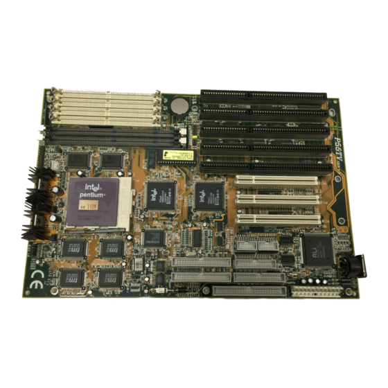
P55TV motherboard
meets the intent of Directive 89/336/ECC for Electromagnetic Compatibility.
Compliance was demonstrated to the following specifications as listed in the
official Journal of the European Communities:
EN 50081-1 Emissions:
EN 55022
EN 55022
EN 60555-2 Power Harmonics
EN 50082-1 Immunity:
IEC
801-2 Electrostatic Discharge
IEC 801-3
IEC 801-4
Radiated, Class B
Conducted, Class B
RF Radiat
Fast Transient
i
Advertisement
Table of Contents

Related Manuals for IWILL P55TV


Summary of Contents for IWILL P55TV
- Page 1 Lin Kou 2nd Industrial Park, Taipei, Taiwan R.O.C. declare under sole responsibility that the P55TV motherboard meets the intent of Directive 89/336/ECC for Electromagnetic Compatibility. Compliance was demonstrated to the following specifications as listed in the official Journal of the European Communities:...
- Page 2 About This Manual This P55TV/TVS SCSI Motherboard is the newest member to our SCSI Motherboard solution products families. It incorporated with Intel 4 generation 430VX Chipset and Adaptec ® new Ultra PCI SCSI AIC-7860(AHA-2940AU) that double the SCSI speed. In order to support fully plug and play Ultra I/O , an Ultra I/O that contain keybaord and real time clock is used for users to enjoy the plug and play function.
-
Page 3: Table Of Contents
Contents Chapter 1- Overview 1.1 Features 1.2 Specif ications Chapter 2- Quick Installation Chapter 3- Hardware Installation 3.1 Preparation and Inspection 3.2 Placement 3.3 CPU group 3.4 Cache Memory 3.5 D-RAM Conf iguration 3.6 SCSI Interf ace 3.7 Creative Sound 3.8 IDE Interf ace 3.9 USB 3.10 Enhanced Multi-IO... -
Page 5: Chapter 1- Overview
HAPTER 1 Overview Thank you for purchasing this P55TV/TVS SCSI Motherboard. This operation manual will guide you to proper configure and install. It has an overview of the engineer design and feature of this board. Also, this manual provides useful information for your later upgrade or change the configuration. - Page 6 ◼ Expansion slots: 5 X 16-bits ISA slots for P55TV, 4 X 16-bits ISA slots for P55TVS . 3 X 32-bits PCI slots for PCI compatible add-on cards. (PCI#2 is occupied by the Adaptec SCSI, it is flexible for your choose while you install a prior or minor controller on this PCI bus.) (PCI Rev 2.1)
-
Page 7: Specifications
◼ Parallel Port IRQ selectable for IRQ5(278h), IRQ7(378h) from system BIOS. Standard mode--Compatible with IBM PC/AT Printer port EPP Mode --Enhanced Parallel Port compatible(EPP) compatible IEEE 1284 ECP Mode --Microsoft & Hewlett Packard Extended Capabilities Port (ECP) Compatible Incorporates ChiProtect Circuit for protection against damage due to printer power-on 1.2 Specifications ◼... -
Page 8: Chapter 2- Quick Installation
Quick Installation This SCSI Motherboard is shipped with manufacture preset at : CPU Clock at 100 MHz Adaptec Ultra SCSI Chip Enabled SCSI Terminator Control by BIOS 512K Pipeline Burst Cache on board Printer ECP Mode at DMA3 Printer at IRQ7 , Address at 378h Serial 1 at IRQ4, Serial 2 at IRQ3 PS/2 MOUSE at IRQ 12 Reference to the Chapter 3 &... -
Page 9: Chapter 3- Hardware Installation
Enter the "Setup Menu" screen by press the " Del " key while power on or warm reset the system. Always "LOAD SETUP DEFAULT" at first and select others necessary that your system require. Step 7. Save the setup data to the CMOS Exit the "Setup Menu "... -
Page 10: Preparation And Inspection
3.1 Preparation and Inspection The P55TV/TVS SCSI Motherboard, like all electronic equipment is static sensitive. Please take the proper precautions when handling this board. You should avoid static up. If possible, You should ground yourself by touching a metal table or your computer frame. Keep the board in its conductive wrapping until it is configured and ready to be installed in your system. -
Page 11: Placement
3.2 Placement... - Page 12 P55TV PS2 m ouse Keyboard Pow er CONN. CONN. PCI#3 PCI#1 PCI#4 COM#B Floppy Printer COM#A Ultra SCSI Prim ary Secondary Bank 0 Bank 1 Soocket 7 Reset SW SCSI LED IDE LED SMI SW Turbo LED Speaker Keylock Placement & Connector...
- Page 13 P55TVS PS2 m ouse Keyboard Pow er CONN. CONN. Sound AdaptorConnector PCI#4 PCI#3 PCI#1 COM #B Floppy Printer COM #A Ultra SCSI Prim ary Secondary Bank 0 Bank 1 Soocket 7 Reset SW SCSI LED IDE LED SMI SW Turbo LED Speaker Keylock Placement &...
- Page 14 P55TV/P55TVS 1-2: Enable SCSI 2-3: Disable SCSI JP17 1-2: 12V Flash ROM(28xxx) 1-2: Terminator alw ays On 2-3: 5V Flash ROM(29xxx) Off: Terminator alw ays Off 2-3: Terminatorcontrol by BIOS P55C P54C Soock e t 7 JP20 JP10 Jumpers...
-
Page 15: Cpu Group
3.3 CPU group 3.3.1 CPU Socket This CPU socket provides flexibility for Intel Pentium , Pentium OverDrive, Pentium future processors, AMD K5(5k86) and Cyrix M1(6x86) processor. When installing the CPU into the Zero Insertion Force ( ZIF ) socket should be very carefully. Lift the handle of this 321 Pin ZIF socket up carefully and insert the CPU into ZIF socket. - Page 16 The CPU fan power connector is a 1 x 3 pin. 3.3.3 CPU Clock Select...
-
Page 17: Cache Memory P14
JP15 is a 2 X 9 pin jumper, with one "colored" jumper cap on it. One and only one jumper cap need to put on this connector for selecting the CPU clock. Just put the colored yellow jumper cap to the speed your CPU really is (the CPU internal/external clock ratio and ISA clock will be automatically selected by setup the JP15) Regarding Cyrix CPU clock setting, please referto Appendix A for detail. -
Page 18: D-Ram Conf Iguration P14
10% faster than traditional asynchronous SRAM. Manufacture default is 512K on-board. 3-5 D-RAM Configuration The P55TV/TVS supports different type of system memory. No jumper needed for this function or configure. This mainboard separates four pieces of 72 pins SIMM(Single In Line Memory Module) into two banks, and also two pieces 168 pins DIMM(Dual In Line Memory Module) into two banks, they use the same address. -
Page 19: Scsi Interface
3.6.1 J2 Ultra SCSI Connector J2 is a 50 pins 16 bit internal Ultra SCSI connector. It attaches the SCSI cable(s) from the P55TV/TVS SCSI controller to the SCSI peripherals. The external SCSI port expansion kit is a optional for your connecting external devices. - Page 20 3.6.3 Set SCSI IDs You must assign a different SCSI ID to each device on the SCSI bus connected to the P55TV/TVS system board. See your SCSI device documentation for directions on how to determine the ID and change it.
- Page 21 A 2 pin jumper connector. This is for SCSI LED. Reference to Chaptor 3.A for more detail. 3.7 Creative sound (P55TVS only) This mainboard provides a 16 bit audio Creative ViBRA. This solution is Sound Blaster 16 compatible, Roland MPU401 mode compatible and fully compliant with Multimedia PC Level 2 specifications.
- Page 22 ◼ 16 bit Sigma -Delta 3.7.5 Mixer Function Description ◼ Sound Blaster 16 register compatible ◼ Mono input improved to be recordable with 8-level of attenuation ◼ Master volumn controllable digitally from external source The mixer is designed to work with analog input/output signal as large as 2Vpp.
-
Page 23: Ide Interface
3.8 IDE Interface 3.8.1 Primary, Secondary IDE Connectors Primary / Secondary IDE are 40 pins internal IDE port connectors. Use a 40 pins flat cable to connect between this connector and the IDE devices. Normally put the boot-up hard disk at the primary IDE channel and other IDE devices at the secondary IDE channel (like CD-ROM). -
Page 24: Enhanced Multi-Io
3.10 Enhanced Multi-IO 3.10.1 J3 FDC Connector J3 is a 34 pins internal Floppy port connector. Use 34 pins flat cable to connect between this connector and floppy drives. 3.10.2 J8 Printer Connector J8 is a 26 pins connector for parallel port. Use a 26 pin IDC flat cable to convert internal port to a standard 25 pin external D-Sub connector. -
Page 25: Other
If you are using the ordinary pa rallel cables running at the EPP or ECP mode that this controller provided, you may experience that the data efforts. 3.10.3 J9/J10 Serial Port & IRQ Select J9/J10 are 10 pins internal Serial 1/Serial 2 port connector. This system board provides two flat cable to convert internal Serial ports to a standard 9 and 25 pins external RS-232 port. - Page 26 POWER CONNECTOR 3.11.3 Keylock, Speaker Turbo Switch, Turbo LED SMI Switch Connectors Note: This motherboard does not support both the “Keylock” & “Turbo” function. The Turbo LED will active as power indicator. Reset Turbo SW Turbo LED SPEAKER KEYLOCK 3.11.4 Flash EPROM Jumper Setting...
- Page 27 Supports flash EPROM (ROM data can be changed on -board, without change/ replace the ROM chip) are supported. JP20 JP17 EPROM type Note 12V Flash EPROM support (28xxx) 5V Flash EPROM *Default support (29xxx) 3.11.5 PS/2 Mouse J5 is a 5 pin connector, connect this port by a 1 x 5 IDC flat cable to a L- frame mini-din PS/2 mouse connector.
-
Page 28: Chapter 4 Award Bios Setup
HAPTER 4 Award BIOS Setup Notice The information in this guide is subject to change without notice. The software described in this guide is furnished under a license agreement and may be used or copied only in accordance with the terms of the agreement. Award Software, Inc. - Page 29 BIOS will seek an operating system on one of the disks and then launch and t urn control over to the operating system. While the BIOS is in control, the Setup program can be activated in one of two ways: By pressing <Del>...
- Page 30 Esc key Main Menu -- Quit and not save changes into CMOS Status Page Setup Menu and Option Page Setup Menu -- Exit current page and return to Main Menu PgUp key Increase the numeric value or make changes PgDn key Decrease the numeric value or make changes + key Increase the numeric value or make changes...
- Page 31 A Final Note About Setup Not all systems have the same Setup. While the basic look and function of the Setup program remains the same for all systems, individual motherboard and chipset combinations require custom configurations. For example, you m ay find that your Setup main menu has a different number of entries from the main menu displayed in this manual.
- Page 32 arrow keys to select among the items and press <Enter> to accept and enter the sub-menu. ROM PCI/ISA BIOS (2A59GI39) CMOS SETUP UTILITY AWARD SOFTWARE, INC. STANDARD CMOS PASSWORD SETTING BIOS FEATURES SETUP IDE HDD AUTO DETECTION CHIPSET FEATURES SETUP HDD LOW LEVEL FORMAT POWER MANAGEMENT SETUP SAVE &...
- Page 33 BIOS Features Setup This setup page includes all the items of Award special enhanced features. Setting Password Setting Change, set, or disable password. It allows you to limit access to the system and Setup, or just to Setup. Chipset Features Setup This setup page includes all the items of chipset special features.
- Page 34 performance, the manufacturer has the right to change these defaults to meet their needs. IDE HDD Auto Detection Automatically detect and configure hard disk parameters. The Award BIOS includes this ability in the event you are uncertain of your hard disk parameters. HDD Low Level Format If supported by your system, this provides a hard...
-
Page 35: Standard Cmos Setup
4.2 Standard CMOS Setup The items in Standard CMOS Setup Menu are divided into 10 categories. Each category includes no, one or more than one setup items. Use the arrow keys to highlight the item and then use the <PgUp> or <PgDn> keys to select the value you want in each item. - Page 36 Daylight saving The category adds one hour to the clock when daylight-saving time begins. It also subtracts one hour when standard time returns. Enabled Enable daylight-saving Disabled Disable daylight-saving Primary Master/ Primary Slave/ Secondary Master/ Secondary Slave The categories identify the types of 2 channels that have been installed in the computer.
- Page 37 Drive A Type / Drive B Type If a hard disk has not been installed Select NONE and press <Enter>. The category identifies the types of floppy disk drive A or drive B that have been installed in the computer. None No floppy drive installed 360K, 5.25 in...
-
Page 38: Bios Features Setup
All errors The system boot will not be stopped for any error that may be detected. All, The system boot will not stop for a keyboard error; it will But Keyboard stop for all other errors. All, But Diskette The system boot will not stop for a disk error; it will stop for all other errors. - Page 39 ROM / PCI ISA BIOS (2A59GI39) BIOS FEATURES SETUP AWARD SOFTWARE, INC. Virus Warning : Disabled Virus Warning : Disabled Video BIOS Shadow Enabled CPU Internal Cache : Enabled C8000-CBFFF Shadow Disabled External Cache : Enabled CC000-CFFFF Shadow Disabled Quick Power On Self Test : Enabled D0000-D3FFF Shadow Disabled...
- Page 40 Enabled Activates automatically when the system boots up causing a warning message to appear when anything attempts to access the boot sector or hard disk partition table. Disabled No warning message will appear when anything attempts to access the boot sector or hard disk partition table. NOTE: Many disk diagnostic programs which attempt to access the boot sector table can cause the above...
- Page 41 C, CDROM, System will first search for hard disk drive , then CDROM drive, and then floppy disk drive. Swap Floppy Drive This item allows you to determine whether enable the swap floppy drive or not. The choice: Enabled/Disabled. Boot Up Floppy Seek During POST, BIOS will determine if the floppy disk drive installed is 40 or 80 tracks.
- Page 42 This entry allows you to select how the gate A20 is handled. The gate A20 is a device used to address memory above 1 Mbytes. Initially, the gate A20 was handled via a pin on the keyboard. Today, while keyboards still provide this support, it is more common, and much faster, for the system chipset to provide support for gate A20.
- Page 43 Typematic Delay (Msec) When the typematic rate is enabled, this selection allows you to select the delay between when the key was first depressed and when the acceleration begins. 250 msec 500 msec 750 msec 1000 1000 msec Security Option This category allows you to limit access to the system and Setup, or just to Setup.
-
Page 44: Chipset Feature Setup
Video BIOS Shadow Determines whether video BIOS will be copied to RAM. However, it is optional depending on chipset design. Video Shadow will increase the video speed. Enabled Video shadow is enabled Disabled Video shadow is disabled C8000 - CBFFF DC000 - DFFFF These categories determine whether option ROMs will be copied to RAM. - Page 45 DRAM Timing : 60s DRAM RAS# Precharge Time DRAM R/W Leadoff Timing : 7/6 Fast RAS# To CAS# Delay DRAM Read Burst <EDO/FPM> : x333/x444 DRAM Read Burst Timing : x444 Turbo Read Leadoff : Enabled DRAM Speculative Leadoff : Disabled Turn-Around Insertion : Disabled ISA Clock...
- Page 46 DRAM Timing The DRAM timing is controlled by the DRAM Timing Registers. The timings programmed into this register are dependent on the system design. Slower rates may be required in certain system designs to support loose layouts or slower memory. 60ns DRAM Timing Type.
- Page 47 3 CPU clocks is the default. DRAM Read <EDO/FPM> This sets the timing for burst mode reads from two different DRAM(EDO/FPM). Burst read and write requests are generated by the CPU in four separate parts. The first part provides the location within the DRAM where the read or write is to take place while the remaining three parts provide the actual data.
- Page 48 DRAM Speculative Leadoff Disabled is the default. The 430HX chipset is capable of allowing a DRAM read request to b e generated slightly before the address has been fully decoded. This can reduce all read latencies. More simply, the CPU will issue a read request and included with this request is the place (address) in memory where the desired data is to be found.
- Page 49 Video BIOS Cacheable As with caching the System BIOS above, enabling the Video BIOS cache will cause access to video BIOS addressed at C0000H to C7FFFH to be cached, if the cache controller is also enabled. Enabled Video BIOS access cached Disabled Video BIOS access not cached Disabled is the default.
-
Page 50: Power Management Setup
Disabled is the default. Peer Concurrency Peer concurrency means that more than one PCI device can be active at a time. Enabled Multiple PCI devices can be active. Disabled Only one PCI device can be active at a time. Enabled is the default. 4.5 Power Management Setup The Power Management Setup allows you to configure you system to most effectively save energy while operating in a manner consistent with your own... - Page 51 ** Wake Up Events In Doze & Standby ** IRQ11 (Reserved) : ON IRQ3 (Wake - Up Event ) : ON IRQ12 (PS/2 Mouse) : ON IRQ4 (Wake - Up Event ) : ON IRQ13 (Coprocessor) : ON IRQ8 (Wake - Up Event ) : ON IRQ14 (Hard Disk) : ON...
- Page 52 When enabled, an Advanced Power Management device will be activated to enhance the Max. Power Saving mode and stop the CPU internal clock. If the Max. Power Saving is not enabled, this will be preset to No. Video Off Method This determines the manner in which the monitor is blanked.
- Page 53 When enabled and after the set time of system inactivity, the hard disk drive will be powered down while all other devices remain active. Power Down & Resume Events Power Down and Resume events are I/O events whose occurrence can prevent the system from entering a power saving mode or can awaken the system from such a mode.
-
Page 54: Pnp/Pci Conf Iguration
4.6 PnP/ PCI Configuration Setup This section describes configuring the PCI bus system. PCI, or Personal Computer Interconnect, is a system which allows I/O devices to operate at speeds nearing the speed the CPU itself uses when communicating with its own special components. - Page 55 IRQ-15 assigned to : PCI/ISA PnP DMA-0 assigned to : PCI/ISA PnP → : Select Item DMA-1 assigned to : PCI/ISA PnP ESC : Quit DMA-3 assigned to : PCI/ISA PnP F1 : Help PU/PD/+/- : Modify DMA-5 assigned to : PCI/ISA PnP F5 : Old Values (Shift) F2 : Color...
- Page 56 Choices are Level (default) and Edge. PCI IDE IRQ Map This allows you to configure your system to the type of IDE disk controller in use. By default, Setup assumes that your controller is an ISA (Industry Standard Architecture) device rather than a PCI controller. The more apparent difference is the type of slot being used.
-
Page 57: Integrated Peripherals
4.7 Integrated Peripherals ROM PCI / ISA BIOS (2A59GI39) INTEGRATED PERIPHERALS AWARD SOFTWARE, INC. IDE HDD Block Mode : Enabled IDE Primary Master : Auto IDE Primary Slave : Auto IDE Secondary Master : Auto IDE Secondary Slave : Auto PCI Slot IDE 2nd Channel : Enabled On-Chip Primary... - Page 58 PCI Slot IDE 2nd Channel This item allows you designate an IDE controller board inserted into one of the physical PCI slots as your secondary IDE controller. Enabled External IDE controller designated as the secondary controller Disabled No IDE controller occupying a PCI slot. Disabled is the default.
-
Page 59: Load Setup Defaults
Disabled Primary HDD controller not used. On-Chip Secondary PCI IDE As above for the Primary controller, this setup item you either to enable or disable the secondary controller. You might choose to disable the controller if you were to add a higher performance or specialized controller. Enabled Primary HDD controller used Disabled... -
Page 60: Ide Hdd Auto Detection
and press <Enter>. You may also press <Esc> to abort the selection and not enter a password. To disable a password, just press <Enter> when you are prompted to enter the password. A message will confirm the password will be disabled. Once the password is disabled, the system will boot and you can enter Setup freely. -
Page 61: 5- Scsi Bios Setup
HAPTER 5 SCSI BIOS Setup 5.1 When to Use the SCSISelect Utility Use the SCSISelect utility if you need to Change any of the default values. ⚫ Check and / or change SCSI device settings that may conflict with ⚫ those of other devices (e.g., SCSI ID). -
Page 62: Scsi Select Utility Option P59
5.2 SCSI Select Utility Options After you press Ctrl + A then it will displays the Options menu as below. AIC-78xx at Bus: Device xx:xxh Arrow keys to move cursor, <Enter> to select option, <Esc> to Exit (*=default) Use the Up and Down keys and the Enter key to make selections in the SCSI Select utility . - Page 63 5.3 Configure/View Host Adapter Settings The Configure / View Host Adapter Settings menu lists three settings under SCSI Channel Interface Definitions , as shown in following Figure. Adaptec AIC-78xx < SCSISelect(TM) > Utility v1.XX AIC-78xx at Bus: Device xx:xxh Configuration SCSI Channel Interface Definitions Host Adapter SCSI ID SCSI Parity Checking...
- Page 64 The SCSI ID serves two purposed : it uniquely identifies each SCSI device on the bus , and it determines the device's priority on the bus during the Arbitration phase. The Arbitration phase determines which device controls the bus when two or more devices request use of it . ...
- Page 65 Disabled Internal and external connectors 5.3.4 Boot Device Configuration This option allows you to choose which SCSI ID device has the Boot right for system O.S. 5.3.5 SCSI Device Configuration This option allows you to configure certain parameters of each SCSI device on the SCSI bus.
- Page 66 When set to no , the SCSI device is not allowed to disconnect from the SCSI bus . The default setting is yes. You should leave Enable Disconnection set to yes if two or more SCSI devices are connected to the on board SCSI port . This optimizes SCSI bus performance.
- Page 67 The SCAM is a Plug & Play specification ⚫ Host Adapter BIOS This option enables or disables the on board SCSI BIOS . The default setting is Enabled. The host adapter BIOS must be enabled if you want the computer to boot from a SCSI hard disk drive connected to the host adapter .
-
Page 68: Scsi Disk Utilities
⚫ Multiple Lun Support This option allows you to enable or disable the SCSI Lun support ◼ BIOS Support for Int13 Extensions This option allows you to Enabled or Disabled the Int13 Extensions. The SCSI BIOS need to change the Int13h to make the SCSI been recognized by O.S. - Page 69 Caution : A low - level format destroy all data on the drive. Be sure to back up your data before performing this operation. You cannot abort a low - level format once it is started. ⚫ Verify Disk Media The Verify Disk Media utility scans the selected device's media for defects .
- Page 70 The Cyrix 6x86 100/120/133Mhz processor rivals the performance of a Intel Pentium 120/150/166Mhz, so the 120+/150+/166+ will be marked on Cyrix CPU Front Size and the motherboard BIOS will show the same reference on the screen. The jumper setting for Cyrix 100Mhz, please refer the following diagram. The jumper setting for Cyrix 120Mhz/133Mhz is the same as Intel‘s setting.
- Page 71 The Cyrix also ship their 6x86 Processors at the voltage specification of 3.52 Volts(also knows as the VRE spec.). Ensure that your motherboard voltage jumper setting are set accordingly. Example: Cyrix 6x86 family of processors (cyrix logo here) 6x86-P166+GP Cyrix CPU Ordering Number 133Mhz Internal CPU Frequency Operating Voltage:...
- Page 72 Example: AMD5K86 family of processors The marking shown below is provided as an example only. It is intended to help you to set the correct CPU Voltage for AMD Processor. The AMD reserves the right to change on this proposed product without notice. Internal CPU Frequency Package Type: A=SPGA...
Need help?
Do you have a question about the P55TV and is the answer not in the manual?
Questions and answers