Table of Contents
Advertisement
Quick Links
Advertisement
Table of Contents

Subscribe to Our Youtube Channel
Related Manuals for ADDER AdderLink XD522


Summary of Contents for ADDER AdderLink XD522
- Page 1 AdderLink XD522 User Guide ...
-
Page 2: Table Of Contents
Audio support ................4 Operation Serial communication support ............4 Tips for achieving good quality links .........5 Front panel indicators ...............21 AdderLink XD522 unit features ..........6 Operating Modes...............21 What’s in the box ................7 Using hotkeys................22 What you may additionally need ..........8 The Dashboard ..............22... -
Page 3: Introduction
Introduction AdderLink XD522 is a high performance KVM (Keyboard, Video, Mouse) extender that enables you to locate your critical computing hardware in a secure and temperature controlled environment away from the user work station whilst maintaining the same user desktop experience. -
Page 4: Video Support
Data) information that each video display provides (detailing their supported of CATx links used to join the transmitter and receiver, AdderLink XD522 resolutions) before reporting them to the host PC. In this way AdderLink XD522 periodically checks the quality of link A (the primary cable joining the transmitter can mask the resolution modes that cannot be supported within the available and receiver). -
Page 5: Usb Support
USB support Audio support AdderLink XD522 units provide support for a wide range of USB devices via four The AdderLink XD522 units can transfer analog and digital audio signals across ports on the receiver unit. Three of the ports (labeled A) support low/full speed the CATx cable link. -
Page 6: Tips For Achieving Good Quality Links
AdderLink XD522 installation is highly dependent upon good quality CATx cable links. Video performance is particularly reliant on high speed communication channels. For this reason, the AdderLink XD522 units periodically test the link quality to determine which of two video transfer modes can be supported: Low Rate or High Rate. -
Page 7: Adderlink Xd522 Unit Features
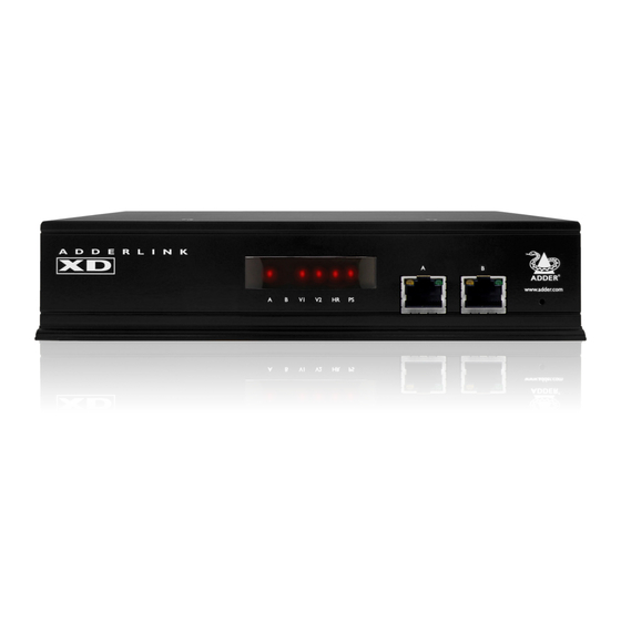
AdderLink XD522 unit features The AdderLink XD522 units are housed within durable, metallic enclosures with port connectors situated on the front and rear panels. The smart front faces also feature the operation indicators. Transmitter - front Receiver - front Headphone/... -
Page 8: What's In The Box
What’s in the box Power adaptor (20W) and country-specific power lead 2 x Audio cable 2m (3.5mm stereo jacks) Part number: VSC22 Transmitter unit Power adaptor (20W) and country-specific power lead 2 x USB cable 2m (type A to B) Part number: VSC24 Receiver unit Serial cable 2m... -
Page 9: What You May Additionally Need
What you may additionally need Two 19” rack-mount brackets and four screws Part numbers: One unit per 1U rack slot: RMK4S Two units per 1U rack slot: RMK4D DisplayPort cable Serial cable 2m USB cable 2m (type A to B) Audio cable 2m Part number: VCSD10 Part number: VSC40... -
Page 10: Installation
Installation Mounting There are two main mounting methods for transmitter and receiver units: • The supplied self-adhesive rubber feet • Optional rack brackets Connections Rack brackets The optional brackets (plus four screws), allow the units to be secured within a standard rack slot. Note: The units and their power supplies generate heat when in operation and will become warm to the touch. -
Page 11: Connections
Connections USB connections Connections to the AdderLink XD522 units do not need to be carried out in the order given within this guide, however, where possible connect the power in as USB connections are made between the host computer and the two sockets on a final step. -
Page 12: Audio Connections
2 If a microphone or other audio input is required (from the AdderLink XD522 Note: This digital input is fed across the main CATx link to the optical receiver back to the host computer), use another 3.5mm jack audio cable connection of the receiver’s Line Out socket only. -
Page 13: Serial Connection
Serial connection Link connections The Options port on the rear panel of every AdderLink XD522 unit operates as a AdderLink XD522 transmitter and receiver units are linked by either one or serial connection that can either: two CATx cables at a distance of up to 150 meters (492 feet). The type and quality of the CATx cables used are crucial to the mode of operation (please •... -
Page 14: Power Connection
Power connection Each AdderLink XD522 unit is supplied with a 20W power adaptor. There is no on/off switch on the unit, so operation begins as soon as a power adaptor is connected. To connect the power supply 1 Attach the output lead from the power adaptor... -
Page 15: Receiver
Data) information that each video display provides (detailing their supported Note: Although port 2 supports DP++ dual-mode operation, it is limited to resolutions) before reporting them to the host PC. In this way AdderLink XD522 154Mpixels/sec (when the AdderLink XD522 units are running in high rate can mask the resolution modes that cannot be supported within the available mode). -
Page 16: Usb Connections
USB connections The AdderLink XD522 receiver provides four USB sockets on its front face: To connect the USB ports 1 Connect the cable from your USB device to one of the vacant USB sockets on the receiver front panel. These three sockets are all... -
Page 17: Audio Connections
Audio connections The AdderLink XD522 units support analog and digital audio. Line in and To connect speakers/line in/analog line out line out connectors are provided on both the transmitter and receiver units. 1 Connect the 3.5mm jack from your powered speakers or the Line In socket... - Page 18 The digital and analog channels run independently alongside each other via the CATx link. Third party adaptors (not supplied) are available to convert between the mini-TOSLINK connections used on the AdderLink XD522 units and the more common full size TOSLINK connectors found on many audio/visual devices. TOSLINK cable...
-
Page 19: Serial Connection
Serial connection Link connections The Options port on the rear panel of every AdderLink XD522 unit operates as a AdderLink XD522 transmitter and receiver units are linked by either one or two serial connection that can either: CATx cables at a distance of up to 150 meters (492 feet). The type and quality of the CATx cables used are crucial to the mode of operation (please see the •... -
Page 20: Power Connection
Power connection Each AdderLink XD522 unit is supplied with a 20W power adaptor. There is no on/off switch on the unit, so operation begins as soon as a power adaptor is connected. To connect the power supply 1 Attach the output lead from the power adaptor to 2 Connect the IEC connector of the supplied country-specific power lead to socket on the rear panel of the unit. -
Page 21: Configuration
Performing an upgrade Choosing the audio input mode AdderLink XD522 units are flash upgradeable using the method outlined here. The AdderLink XD522 receiver has two analog audio inputs: A microphone The same upgrade file is used to upgrade both the transmitter and receiver units socket on the front panel and a Line In socket on the rear. -
Page 22: Operation
Front panel indicators Operating Modes AdderLink XD522 units try at all times to maximize the data that can be The six front panel indicators on each unit provide a useful guide to operation: transferred between them. The achievable throughput depends upon the length Tips for achieving and quality of the cable links that join the units. -
Page 23: Using Hotkeys
Using hotkeys The Dashboard The AdderLink XD522 units provide hotkey features to allow you to check and adjust certain aspects of operation. Using the hotkeys you can: The Dashboard provides a quick overview of link quality as well as confirmation •... -
Page 24: Further Information
• Radio frequency energy statements For technical support, use the contact form in the Support section of the adder.com website - your regional office will then get in contact with you. General specifications Casing (w x h x d): 198mm (7.92”) x 44mm (1.76”) x 120mm (4.8”) - Page 25 Appendix A Options port pin-out The Options port on each unit can accept either 8p8c or 10p10c connectors, as required. 8p8c 10p10c Signal Not used 5VDC power output (100mA max) GND reference for all signals RS232 (RXD) data receive RS232 auxiliary data transmit (reserved) OPTIONS RS232 auxiliary data receive (reserved) RS232 (TXD) data transmit...
- Page 26 Appendix B EDID management This flowchart highlights how the AdderLink XD522 units determine which of the various modes reported by each video display can be supported by the installation.
-
Page 27: Appendix C - Tested Video Resolutions
Tested video resolutions This section details the video resolutions that have been tested with the AdderLink XD522 units and are known to work within the link limitations detailed elsewhere in this guide for the operational modes. All quoted video resolutions have reduced blanking. -
Page 28: Appendix D - Link Cable Interference Protection
Appendix D Link cable interference protection While the Category rating (e.g. CAT 5e, CAT 6a, etc.) determines the electrical performance of a cable, another vital part of the overall cable specification is its protection U/UTP from interference. As cabling distances and data rates increase, so too does the susceptibility to interference, from both external and internal sources. -
Page 29: Warranty
• No user serviceable parts within power adaptor - do not dismantle. warranty period, Adder will replace or repair it free of charge. No liability can be • Plug the power adaptor into a socket outlet close to the module that it is accepted for damage due to misuse or circumstances outside Adder’s control. -
Page 30: Radio Frequency Energy
Radio Frequency Energy A Category 5 (or better) twisted pair cable must be used to connect the units in order to maintain compliance with radio frequency energy emission regulations and ensure a suitably high level of immunity to electromagnetic disturbances. All other interface cables used with this equipment must be shielded in order to maintain compliance with radio frequency energy emission regulations and ensure a suitably high level of immunity to electromagnetic disturbances. - Page 31 Web: www.adder.com www.adder.com/contact-details Contact: Support: forum.adder.com © 2013 Adder Technology Limited All trademarks are acknowledged. Documentation by: www.ctxd.com Part No. MAN-XD5x2-ADDER • Release 1.0a...
-
Page 32: Index
Index EDID 25,26,27 Line In 20,22 Resolutions Analogue audio 11 EDID management 3 Link video 3 adapter 14 Audio RX connections 18 RS232 12,18 Video hotkey switch 16 TX connections 12 modes 3 RX connections 16 Link quality 5 RX connections 14 Flash upgrade 20 TX connections 11 Low Rate 22...
Need help?
Do you have a question about the AdderLink XD522 and is the answer not in the manual?
Questions and answers