Table of Contents
Advertisement
Quick Links
Download this manual
See also:
Manual
Advertisement
Table of Contents

Related Manuals for ADDER X2


Summary of Contents for ADDER X2
- Page 1 AdderLink X2 Multi Screen Remote Extenders V I D V I D V I D V I D V I D V I D V I D U / K I T C V I D V I D V I D...
-
Page 2: Table Of Contents
Stage C - Reconfigure the LOCAL connections ...25 Stage D - Reconfigure the REMOTE connections...25 Stage E - Return all connections to their usual states ...25 Further information Troubleshooting ...26 Getting assistance...27 Products in the X2-Series range...28 Cables ...28 Radio Frequency Energy ...29... -
Page 3: Introduction
Welcome Introduction Thank you for choosing the AdderLink X2 Multi Screen extenders. Comprising two compact modules, these extenders allow you to place multiple video monitors and serial devices together with a keyboard, mouse and audio peripherals up to 200 metres from a computer system. In addition, locally... -
Page 4: Supplied Items
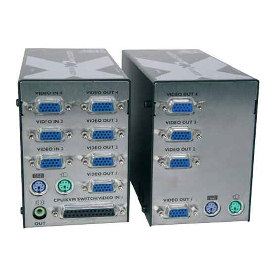
Supplied items X2 Multi Screen MS2 LOCAL module REMOTE module V I D V I D V I D V I D V I D U /K I T C H /V MS2: Keyboard, mouse, audio, two video and two serial channels... -
Page 5: Module Features
Connection to local speakers I T C V I D Multi-cable connection from computer REMOTE X2 Multi Screen module (MS4 model pictured) * not available on MS2 model. Power supply connection Connections for serial ports 1, 2, 3* and 4*... -
Page 6: Installation And Operation
Installation and operation Installation The installation of the X2 Multi Screen extenders is straightforward and can best be achieved in most cases by following these stages for each module: • Stage A Check or set the configuration switch settings • Stage B Mount the module •... -
Page 7: Remote Module Switches
REMOTE module switches OFF: Normal operation ON: Flash upgrade Determines configuration of hotkeys in conjunction with switch 2 Note: When shipped, all switches are set in the OFF positions and this will produce normal operation. REMOTE module switches (continued) REMOTE Switch 1 Determines configuration of hotkeys in conjunction OFF: Normal operation. -
Page 8: Stage B - Mounting A Module - Desk Or Rack
Stage B - Mounting a module – desk or rack The X2 Multi Screen extender modules can be situated on a desk (or floor) or alternatively, for larger installations, mounted within optional rack mount chassis units. Desk mount Apply the supplied self-adhesive rubber feet to the underside of the module(s). -
Page 9: Stage C - Connections
Stage C - Connections The naming of the LOCAL and REMOTE modules relate to their proximity to the host computer system. Hence, the LOCAL module connects directly to the system (and the local peripherals), while the REMOTE is at the other end of the twisted pair cable and attaches to the duplicate keyboard, mouse, etc. - Page 10 Additional video channel inputs The MS2 model provides a second video channel, and the MS4 model provides a further three channels, in addition to the main video channel that enters via the multi-cable connection. 1 Use the supplied video connection cable(s) to make a link between the additional...
- Page 11 The MS2 LOCAL module requires a separate power input only when the keyboard connection to the host system is not used. Separate power supply units are available from Adder Technology Limited direct (www.shop.adder.com) or from your local supplier - part number: PSU-IEC- 5VDC.
-
Page 12: Connections At The Remote Module
Connections at the REMOTE module Keyboard and mouse connections 1 Connect the keyboard lead to the purple mini-DIN socket labelled on the REMOTE module. 2 Connect the keyboard lead to the green mini-DIN socket labelled Connection from keyboard the REMOTE module. Audio connections At the REMOTE module, audio connections are available from the two 3.5”... - Page 13 Video outputs You can connect multiple video monitors to the REMOTE module (up to two on the MS2 model or up to four on the MS4 model). 1 Attach the signal leads from each video monitor to the output sockets (labelled VIDEO OUT ) on...
- Page 14 Power connection 1 Attach the output connector of the power supply to the socket of the REMOTE module, labelled POWER Power supply connection 2 Insert the IEC connector of the supplied power lead into the corresponding socket of the power supply. Connect the other end of the power lead to a nearby mains socket.
-
Page 15: Operation
Control of the host system is arbitrated by R I A the X2 Multi Screen modules on a first come, first served basis. In the idle state, control is available to both users and their keyboard indicators both show the current Num Lock, etc. -
Page 16: Locking And Unlocking The System
Locking and unlocking the system In situations where the computer system (and the LOCAL module) can be locked away, the X2 Multi Screen modules offer a viable security system to deter unauthorised use. Once a password has been set, a simple key sequence allows the system to be quickly and securely detached from its peripherals. -
Page 17: Special Configuration
Special configuration Configuration You can alter the way that the X2 Multi Screen modules operate to suit your requirements. This is done using the Configuration mode and you can affect the following settings: • Password setting – allows you to lock the remote module to prevent unauthorised system access. -
Page 18: Password Setting
Password setting Password protection allows you restrict access to the system only to authorised personnel. A password first needs to be set and then, using the keyboard attached to the REMOTE module, a simple key sequence allows the system to be quickly and securely detached from its peripherals. -
Page 19: Hot Plugging And Mouse Restoration
It is strongly recommended that you switch off the computer system before attempting to connect it via the X2 Multi Screen modules. However, if this is not possible then you need to ‘hot plug’ the modules while power is still applied to the system. -
Page 20: Image Controls - Sharpness And Brightness
Image controls - sharpness and brightness The X2 Multi Screen modules incorporate special controls to compensate for losses incurred within long cable links. Using these controls you can adjust the picture sharpness and brightness to improve your remote picture quality. The controls allow you to either affect all of the video channels collectively, or where losses are inconsistent, select and adjust channels individually. - Page 21 Image controls - sharpness and brightness (continued) To use the image controls 1 Simultaneously, press the hotkeys (by default, ) along with to enter configuration mode. The three keyboard indicators (‘Num Lock’, ‘Caps Lock’ and ‘Scroll Lock’) will now begin to flash in sequence.
-
Page 22: Skew Adjustment
Skew adjustment The twisted pair cabling supported by the X2 Multi Screen modules (category 5, or higher) consists of four pairs of wires per cable. Three of these pairs are used by the modules to convey red, green and blue video signals to the remote video monitor. - Page 23 Skew adjustment (continued) 3 Simultaneously, press the hotkeys (by default, ) along with to enter configuration mode. The three keyboard indicators (‘Num Lock’, ‘Caps Lock’ and ‘Scroll Lock’) will now begin to flash in sequence. 4 [OPTIONAL STEP] By default, your skew adjustments are applied equally to all of the video channels.
-
Page 24: Miscellaneous Settings
These can be achieved once within configuration mode by pressing the indicated keys: Report X2 Multi Screen firmware version - Before initiating this command, ensure that the system is running an application that can display typed keys as screen characters - e.g. a word processor or Windows Notepad. -
Page 25: Flash Upgrade
• Stage E – Return all connections to their usual states Stage A - Download the upgrade files To download the files 1 Access the Adder Technology Ltd website (www.adder.com), enter the Support section. Choose the upgrade option that best suits your requirements and download it to your system. -
Page 26: Stage C - Reconfigure The Local Connections
Stage C - Reconfigure the LOCAL connections and begin 1 On the computer from which you will run the upgrade, ensure that its BIOS settings will allow it to boot from the floppy diskette drive, rather than booting immediately from the hard drive. 2 Switch off the computer and disconnect the twisted pair cable from the LOCAL module. -
Page 27: Further Information
Further information Troubleshooting If you experience problems when installing or using the X2 Multi Screen modules, please check through this section for a possible solution. If your problem is not listed here and you cannot resolve the issue, then please refer to the ‘Getting assistance’... -
Page 28: Getting Assistance
Warranty Adder Technology Ltd warrants that this product shall be free from defects in workmanship and materials for a period of two years from the date of original purchase. If the product should fail to operate correctly in normal use during the warranty period, Adder will replace or repair it free of charge. -
Page 29: Products In The X2-Series Range Cables
• single slot blanking plate (part code: X-RMK-BLANK) • quad slot blanking plate (part code: X-RMK-BLANK4) Cables These extra cables are available for use when connecting X2 modules to systems and peripherals: • Serial cable - 9 way male to 9 way female D-type, 2 metres (part code: CAB9M/9F-2M) •... -
Page 30: Radio Frequency Energy
Radio Frequency Energy A Category 5 (or better) twisted pair cable must be used to connect the X2 modules in order to maintain compliance with radio frequency energy emission regulations and ensure a suitably high level of immunity to electromagnetic disturbances. - Page 31 © 2005 Adder Technology Limited All trademarks are acknowledged. Release 1.0c August 2005 Part No. ADD0058 Adder Technology Limited, Technology House, Trafalgar Way, Bar Hill, Cambridge, CB3 8SQ, United Kingdom Tel: +44 (0)1954 780044 Fax: +44 (0)1954 780081 Documentation by: www.ctxd.com...
Need help?
Do you have a question about the X2 and is the answer not in the manual?
Questions and answers