
Subscribe to Our Youtube Channel
Related Manuals for ADDER ADDERLink XD612


Summary of Contents for ADDER ADDERLink XD612
- Page 1 ADDERLink XD612 and XD614 ™ User Guide Experts in Extender Connectivity Solutions Solutions...
-
Page 2: Table Of Contents
Accessing the Dashboard .................20 CATx Link Cable Recommendations ............3 Choosing RX video mode (XD614 models only)........20 Multi-display support using MST ...............4 Resetting a module ....................21 AdderLink XD612 features ................6 Upgrading Firmware ..................21 AdderLink XD614 features ................7 Operation Technical specifications ..................8 Indicators ......................22... -
Page 3: Welcome
Introduction WELCOME Transmission distances when using fiber Thank you for choosing the ADDERLink ® XD612 (dual head) or XD614 (quad head) extender modules. Using either fiber optic or CATx links, these compact modules The choice of fiber used with the ADDERLink XD modules has a considerable effect on the distance over which operation can take place. -
Page 4: Catx Link Cable Recommendations
CATx Link Cable Recommendations Due to the high data bandwidth required between the transmitter and receiver, ADDERLink XD600 series modules are highly dependent upon good quality CATx cable links. Video performance is particularly reliant on high speed communication channels. The main factors that affect link quality are: •... -
Page 5: Multi-Display Support Using Mst
MULTI-DISPLAY SUPPORT USING MST The ADDERLink XD612 and 614 models support the MST (Multi-Stream Transport) protocol, which was introduced in the DisplayPort 1.2 standard. MST allows feeds for multiple video displays to be fed along a single cable. The XD612 and XD614 models use this feature in different ways. - Page 6 @ 60 fps @ 60 fps the video output port. ADDERLink XD614 supports XD614 TX just one console video display Adder does not supply MST hubs, but can recommend the following models: USB link at the transmitter. If other ADDERLink ™ TRANSMIT...
-
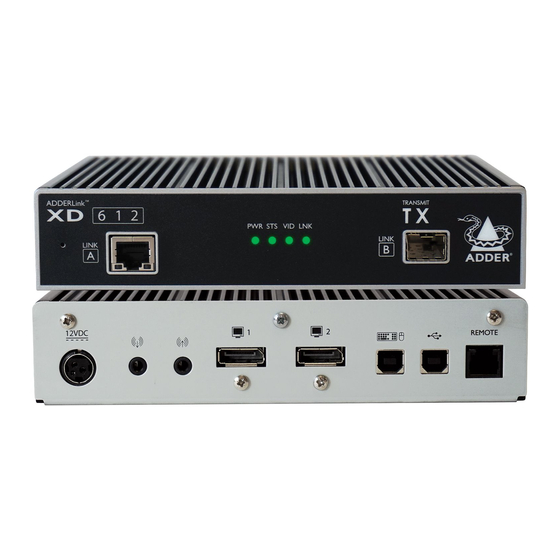
Page 7: Adderlink Xd612 Features
ADDERLINK XD612 FEATURES The transmitter and receiver modules are contained within slimline metal casings that measure just 186 x 152 x 40mm. Transmitter module Receiver module TRANSMIT ™ R E C E I V E ADDERLink ™ ADDERLink 6 1 2 6 1 2 STS VID LNK PWR STS VID LNK LINK... -
Page 8: Adderlink Xd614 Features
ADDERLINK XD614 FEATURES The transmitter and receiver modules are contained within slimline metal casings that measure just 186 x 152 x 40mm. Transmitter module Receiver module TRANSMIT ™ R E C E I V E ADDERLink ™ ADDERLink 6 1 4 6 1 4 STS VID LNK PWR STS VID LNK LINK... -
Page 9: Technical Specifications
TECHNICAL SPECIFICATIONS ADDERLink XD612 / 614 • Nominal Operating Power (W) • Peak Power (W) • External Power 12V DC, 1.5A • Max operating Altitude (m) 2000m • Operating Temp range (°C) 0 to +40°C • Operating Humidity range (%RH) 0-80% • Storage Temp range (°C) -10 to +50°C •... -
Page 10: Supplied Items
SUPPLIED ITEMS XD61x transmitter kit USB cable 2m (type A to B) L IN V ID S T S DisplayPort cable 2m Power adapter with Audio cable 3m locking connector (3.5mm stereo and country-specific jacks) ™ in k power cord L IN ADDERLink XD61x transmitter module Information wallet containing: Quick setup guide Eight self-adhesive rubber feet Safety document XD61x receiver kit V ID Information wallet Power adapter with containing:... -
Page 11: Optional Extras
OPTIONAL EXTRAS Replacement power adapter with locking connector Part number: PSU-IEC-12VDC-1.5A Country-specific power cords CAB-IEC-AUS (Australia) CAB-IEC-EURO (Central Europe) SFP+ module with LC connectors CAB-IEC-UK (United Kingdom) CAB-IEC-USA (United States) Multi mode: SFP+-MM-LC-10G CAB-IEC-JAPAN (Japan) Single mode: SFP+-SM-LC-10G USB cable 2m (type A to B) Audio cable 2m (3.5mm stereo jacks) Part number: VSC24 Part number: VSC22 Remote port serial cable 44cm Part number: VSC50 DisplayPort cables 2m Part numbers: •... -
Page 12: Installation
Installation LOCATIONS Please consider the following important points when planning the position of the Suitable for installation in Information AdderLink XD modules: Technology Rooms in accordance with Article 645 of the National Electrical Code and • Situate the transmitter module close to the system to which it will be connected and NFPA 75. -
Page 13: Transmitter Video Link(S)
Transmitter video link(s) Transmitter audio links VIDEO VIDEO AdderLink XD modules can transfer various The AdderLink XD modules support LINK(S) LINK(S) AUDIO AUDIO high resolution video modes via their analog stereo audio in and out LINKS LINKS DisplayPort connectors. The XD612 models connections. -
Page 14: Transmitter Usb Links
The ports have different functions: 115200 baud - no serial configuration is required. An optional serial cable (part number: VSC50) is available from Adder. USB HID (Human Interface Device) USB audio feed to/from the analog audio... -
Page 15: Transmitter Power Connection
Transmitter power connection VIDEO There is no on/off switch on either of the LINK(S) AUDIO AdderLink XD modules, so operation LINKS begins as soon as power is applied. The power adapters supplied with the modules TRANSMITTER LINK LINK(S) use locking-type plugs to help prevent accidental disconnections;... -
Page 16: Linking
Linking ADDERLink XD transmitters and receivers can be linked using either: • CATx (see below), or • Fiber (see next page) CATx link CATx status indicators The CATx ports on each module (labeled Link A) allow you to create direct links of up to 50m (when using The status indicators on the CATx port connector CAT5e) or 100m (when using CAT6). -
Page 17: Fiber Optic Link
XD receiver slot is situated on the rear panel: Note: In order to maintain a high level of confidence in the fiber optic link, it is recommended that Adder supplied SFPs are used: L I N (SFP+-MM-LC-10G or SFP+-SM-LC-10G). -
Page 18: Receiver Video Display(S)
Receiver video display(s) Receiver audio devices VIDEO VIDEO Two DisplayPort sockets are provided on The receiver module can support multiple DISPLAY(S) DISPLAY(S) AUDIO AUDIO the rear panel of each receiver module. On analog audio devices, such as stereo TRANSMITTER TRANSMITTER DEVICES DEVICES XD612 models, video streams 1 and 2 are headphones, a mono microphone or line- presented at the ports. -
Page 19: Receiver Usb Devices
To connect USB devices 115200 baud - no serial configuration is required. An optional serial cable (part number: VSC50) is available from Adder. 1 Connect your USB keyboard, mouse and any other two USB devices to the four sockets i n k ™... -
Page 20: Receiver Power Connection
Receiver power connection VIDEO There is no on/off switch on either of the DISPLAY(S) AUDIO AdderLink XD modules, so operation TRANSMITTER DEVICES begins as soon as power is applied. The power adapters supplied with the modules RECEIVER LINK DEVICES use locking-type plugs to help prevent accidental disconnections;... -
Page 21: Configuration
Configuration ACCESSING THE DASHBOARD CHOOSING RX VIDEO MODE (XD614 models only) AdderLink XD modules generally configure themselves automatically, collecting EDID ADDERLink XD receivers contain an internal DisplayPort MST hub. On the XD614 information from the attached monitor(s) and passing the details to the host computer. models you can choose to either use it or bypass it. When bypassed (default setting), Unless an issue is encountered, the modules will begin working together correctly as the full combined MST (Multi-Stream Transport) signal received from the transmitter soon as they are connected. -
Page 22: Resetting A Module
UPGRADING FIRMWARE On the left side of the front panel of each module, you will find a small reset hole which Firmware upgrades are periodically made available for products via the Adder website is used to invoke special functions. (www.adder.com). Use this procedure to upgrade the firmware in both ADDERLink XD extenders. -
Page 23: Operation
Operation The AdderLink XD modules are designed to be transparent in operation; all peripherals should respond exactly as they would when situated next to your host computer. INDICATORS The transmitter and receiver modules contain various indicators to provide you with status information. -
Page 24: Further Information
This chapter contains a variety of information, including the following: If you are still experiencing problems after checking the information contained within this • Getting assistance - see right guide, then please refer to the Support section of our website: • Appendix 1 - Remote (Options) port pin-out www.adder.com... -
Page 25: Appendix 1 - Remote Port Pin-Out
APPENDIX 1 - REMOTE PORT PIN-OUT port uses a 6p6c socket. The pin-out is listed below. REMOTE Note: Although the pins labeled ‘Not used’ is inactive, it is still connected internally and so no links should be made at all to this pin. REMOTE Pin Signal Sense/5V Not used... - Page 26 © 2021 Adder Technology Limited All trademarks are acknowledged. www.ctxd.com Documentation by: Part No. MAN-000014 • Release 1.4...
- Page 27 Index Audio devices Linking SFP+ modules 2,16 Receiver 17 overview 15 Single-Stream Transport 20 Audio links SST 20 transmitter 12 Status indicators 22 MST 4,20 Supplied items 9 Multi-Stream Transport 20 CATx link 15 Upgrade Optional extras 10 status indicators 15 firmware 21 Connections USB devices...
Need help?
Do you have a question about the ADDERLink XD612 and is the answer not in the manual?
Questions and answers