
Related Manuals for ADDER AdderLink X2 Dual Access


Summary of Contents for ADDER AdderLink X2 Dual Access
- Page 1 AdderLink X2 Dual Access Remote Extenders V I D V I D I T C I T C ...
-
Page 2: Table Of Contents
Contents Welcome Introduction ...2 Supplied items - X2 Dual Access Silver ...3 Supplied items - X2 Dual Access Gold ...4 Installation and operation Installation ...5 Stage A - Configuration switch settings ...5 LOCAL module switches...5 REMOTE module switches ...6 Stage B - Mounting a module – desk or rack ...7 Installation Advice...7 Stage C - Connections...8 Connections at the LOCAL module ...8... -
Page 3: Introduction
Welcome Introduction Thank you for choosing the AdderLink X2 Dual Access extenders. Comprising two compact modules, the X2 Dual Access extenders allow you to place a duplicate keyboard, video monitor, mouse and a serial device up to 300 metres from a computer system. Two users can simultaneously view the output of the host system and either can take control, providing it is not being used by the other user. -
Page 4: Supplied Items - X2 Dual Access Silver
Supplied items - X2 Dual Access Silver Switch bank to determine certain modes and functions Keyboard, video and mouse connections to peripherals V I D I T C Multi-cable connection from computer Switch bank to determine certain modes and functions Connection to video Connection... -
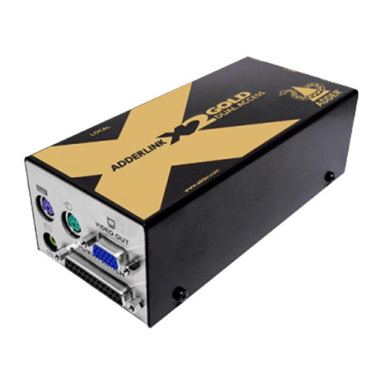
Page 5: Supplied Items - X2 Dual Access Gold
Supplied items - X2 Dual Access Gold Switch bank to determine certain modes and functions Keyboard, video and mouse connections to peripherals Connection for local speakers V I D I T C Multi-cable connection from computer Switch bank to determine certain modes and functions Connections for... -
Page 6: Installation And Operation
Installation and operation Installation The installation of the X2 Dual Access extenders is straightforward and can best be achieved in most cases by following these stages for each module: • Stage A Check or set the configuration switch settings • Stage B Mount the module •... -
Page 7: Remote Module Switches
REMOTE module switches OFF: Normal operation ON: Flash upgrade Determines configuration of hotkeys in conjunction with switch 2 Note: When shipped, all switches are set in the OFF positions and this will produce normal operation. REMOTE module switches (continued) REMOTE Switch 1 Determines configuration of hotkeys in conjunction OFF: Normal operation. -
Page 8: Stage B - Mounting A Module - Desk Or Rack
Stage B - Mounting a module – desk or rack The X2 Dual Access extender modules can be situated on a desk (or floor) or alternatively, for larger installations, mounted within optional rack mount chassis units. Desk mount Apply the supplied self-adhesive rubber feet to the underside of the module(s). -
Page 9: Stage C - Connections
Stage C - Connections The naming of the LOCAL and REMOTE modules relate to their proximity to the computer system. Hence, the LOCAL module connects directly to the system (and the local peripherals), while the REMOTE is at the other end of the twisted pair cable and attaches to the duplicate keyboard, mouse, etc. - Page 10 REMOTE module. Separate power supply units are available from Adder Technology Limited direct (www.shop.adder.com) or from your local supplier - part number: PSU-IEC- 5VDC.
-
Page 11: Connections At The Remote Module
Connections at the REMOTE module Keyboard, video and mouse connections The connections to the keyboard, video monitor and mouse are all made to the sockets at one end of the REMOTE module. 1 Attach the lead from the monitor to the blue D-type socket labelled on the... - Page 12 Audio connections (Gold only) On the X2 Gold REMOTE module, audio connections are available at the two 3.5” jack sockets mounted on the side (same side as the switch bank). Note: The microphone input (labelled ) has a dual function whereby it can either support a mono-channel microphone or alternatively receive stereo line input.
-
Page 13: Operation
Operation Power and activity indicators On the front panel of both modules are small recessed indicators which provide confirmation of power and activity, as follows: • Constant red - power applied, no communication activity. • Flickering red - power applied, mouse or keyboard activity occuring. -
Page 14: Locking And Unlocking The System
Locking and unlocking the system In situations where the computer system (and the LOCAL module) can be locked away, the X2 Dual Access modules offer a viable security system to deter unauthorised use. Once a password has been set, a simple key sequence allows the system to be quickly and securely detached from its peripherals. -
Page 15: Special Configuration
Special configuration Configuration You can alter the way that the X2 Dual Access modules operate to suit your requirements. This is done using the Configuration mode and you can affect the following settings: • Password setting – allows you to lock the remote module to prevent unauthorised system access. -
Page 16: Password Setting
Password setting Password protection allows you restrict access to the system only to authorised personnel. A password first needs to be set and then, using the keyboard attached to the REMOTE module, a simple key sequence allows the system to be quickly and securely detached from its peripherals. -
Page 17: Hot Plugging And Mouse Restoration
Hot plugging and mouse restoration It is strongly recommended that you switch off the computer system before attempting to connect it via the X2 Dual Access modules. However, if this is not possible then you need to ‘hot plug’ the X2 Dual Access modules while power is still applied to the system. -
Page 18: Image Controls - Sharpness And Brightness
Image controls - sharpness and brightness The X2 Dual Access modules incorporate special controls to compensate for losses incurred within long cable links. Using these controls you can adjust the picture sharpness and brightness to improve your remote picture quality. The need for image control adjustment is best discovered when viewing high contrast images with vertical edges, such as black lines on a white background. -
Page 19: Skew Adjustment
Skew adjustment The twisted pair cabling supported by the X2 Dual Access modules (category 5, or higher) consists of four pairs of cables. Three of these pairs are used by the modules to convey red, green and blue video signals to the remote video monitor. Due to the slight difference in twist rate between these three pairs, the red, green and blue video signals may not arrive at precisely the same time. -
Page 20: Miscellaneous Settings
Miscellaneous settings The following are configuration settings within the modules that are not covered in other sections of this guide. These can be achieved once within configuration mode by pressing the indicated keys: Report X2 Dual Access firmware version - Before initiating this command, ensure that the system is running an application that can display typed keys as screen characters - e.g. -
Page 21: Flash Upgrade
• Stage E – Return all connections to their usual states Stage A - Download the upgrade files To download the files 1 Access the Adder Technology Ltd website (www.adder.com), enter the Support section. Choose the upgrade option that best suits your requirements and download it to your system. -
Page 22: Stage C - Reconfigure The Local Connections And Begin
Stage C - Reconfigure the LOCAL connections and begin 1 On the computer from which you will run the upgrade, ensure that its BIOS settings will allow it to boot from the floppy diskette drive, rather than booting immediately from the hard drive. 2 Switch off the computer and disconnect the twisted pair cable from the LOCAL module. -
Page 23: Further Information
If you are still experiencing problems after checking the list of solutions in the Troubleshooting section then we provide a number of other solutions: • Adder Technology website – www.adder.com Check the Support section of our website for the latest solutions. -
Page 24: Safety Information
Warranty Adder Technology Ltd warrants that this product shall be free from defects in workmanship and materials for a period of two years from the date of original purchase. If the product should fail to operate correctly in normal use during the warranty period, Adder will replace or repair it free of charge. -
Page 25: Radio Frequency Energy
Radio Frequency Energy A Category 5 (or better) twisted pair cable must be used to connect the X2 modules in order to maintain compliance with radio frequency energy emission regulations and ensure a suitably high level of immunity to electromagnetic disturbances. - Page 26 © 2005 Adder Technology Limited All trademarks are acknowledged. Release 1.0c August 2005 Part No. ADD0057 Adder Technology Limited, Technology House, Trafalgar Way, Bar Hill, Cambridge, CB3 8SQ, United Kingdom Tel: +44 (0)1954 780044 Fax: +44 (0)1954 780081 Documentation by: www.ctxd.com...
Need help?
Do you have a question about the AdderLink X2 Dual Access and is the answer not in the manual?
Questions and answers