
Related Manuals for Texas Instruments EV2300


Summary of Contents for Texas Instruments EV2300
- Page 1 EV2300 Evaluation Module Interface Board User’s Guide February 2005 PMP EVMs SLUU159A...
- Page 2 IMPORTANT NOTICE Texas Instruments Incorporated and its subsidiaries (TI) reserve the right to make corrections, modifications, enhancements, improvements, and other changes to its products and services at any time and to discontinue any product or service without notice. Customers should obtain the latest relevant information before placing orders and should verify that such information is current and complete.
- Page 3 EVM IMPORTANT NOTICE Texas Instruments (TI) provides the enclosed product(s) under the following conditions: This evaluation kit being sold by TI is intended for use for ENGINEERING DEVELOPMENT OR EVALUATION PURPOSES ONLY and is not considered by TI to be fit for commercial use. As such, the goods being provided may not be complete in terms of required design-, marketing-, and/or manufacturing-related protective considerations, including product safety measures typically found in the end product incorporating the goods.
- Page 4 EVM schematic located in the EVM User’s Guide. When placing measurement probes near these devices during operation, please be aware that these devices may be very warm to the touch. Mailing Address: Texas Instruments Post Office Box 655303 Dallas, Texas 75265 Copyright © 2005, Texas Instruments Incorporated...
-
Page 5: Read This First
Preface Read This First About This Manual This users guide describes the function and operation of the EV2300 evalua- tion module. A complete description, as well as schematic diagram and bill of materials are included. How to Use This Manual This document contains the following chapters: Chapter 1—Introduction... - Page 6 Contents The information in a caution or a warning is provided for your protection. Please read each caution and warning carefully. This EVM contains components that can potentially be damaged by electrostatic discharge, Always transport and store the EVM in its supplied ESD bag when not in use.
-
Page 7: Table Of Contents
........... EV2300 Bill of Materials, Component Placement, and Schematic . - Page 8 Contents viii...
-
Page 9: Introduction
Chapter 1 Introduction This EVM interface board enables an IBM-compatible or other type (with required driver for the particular platform) PC to communicate with Texas Instruments SMBus, HDQ or DQ interface gas gauges via a Universal Serial Bus (USB) port. In addition to this board, PC software is required to interpret the gas gauge data to complete the evaluation system. -
Page 10: Features
Capable of providing a 25-mA 3.3-V source Complete interface between USB and SMBus, I C, and HDQ (8/16) inter- faces using a simple API 1.2 Kit Contents EV2300 circuit module Standard USB cable 1.3 Ordering Information Table 1−1. Ordering Information EVM Part Number... -
Page 11: Interfaces
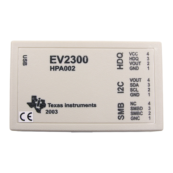
Chapter 2 Interfaces The EV2300 interfaces are described in the following table. The reference designators on the circuit board and the functions are also listed. Reference Designator Function Description HDQ and SMB SMBus, HDQ and DQ Terminal block for connecting to a target device... -
Page 12: Overview
The EV2300 is enclosed and is provided as shown. 2.2 EV2300 Controller The EV2300 controller is a bq8012 running at 4 MHz. The controller firmware is stored in flash memory and is executed by the core at power-up after the boot ROM code verifies the integrity words. -
Page 13: Usb Interface (Usb)
PEC. The SMBus limits the capacitance on each line (Data and Clock) to 100 pF. The EV2300 places 8 pF on each line, so a device may place up to 92 pF total. If the capacitive load approaches or exceeds 100 pF, SMBus communication may not be reliable. -
Page 14: I 2 C/Eeprom Interface (I 2 C)
I2C/EEPROM Interface (I2C) 2.5 I C/EEPROM Interface (I This interface allows a host computer to interact with a target E PROM or other C interface device such as a battery monitor device through a two-wire I interface. The interface contains a controlled power pin, the I C clock and data lines, and a ground reference. -
Page 15: Ev2300 Bill Of Materials, Component Placement, And Schematic
Chapter 3 EV2300 Bill of Materials, Component Placement, Schematic This chapter includes the schematic, component placement on the circuit board, and a listing of the bill of materials for the EV2300 EVM. Topic Page Bill of Materials (BOM) ......... -
Page 16: Bill Of Materials (Bom)
Bill of Materials (BOM) 3.1 Bill of Materials (BOM) Ref Des Description Size Part Number C1−C7, Capacitor, ceramic, 0.1 µF, 25 V, X7R, C1608X7R1E104KT C10−C12, C15, C20 Open C16, C21 Capacitor, POSCAP 4.7 µF, 35 V, 20% 6032 (C) TAJC475K035R Capacitor, ceramic, 2200 pF, 50 V, C1608C0G1H222KT C0G, 10%... - Page 17 Wire colors for pin numbers are listed below. Strip and tin flying leads 0.25 inches from end of wire. Red − pin #4 (signal VOUT) Brown − pin #3 (signal SDA) White − pin #2 (signal SCL) Black − pin #1 (GND) EV2300 Bill of Materials, Component Placement, Schematic...
-
Page 18: Ev2300 Component Placement
EV2300 Component Placement 3.2 EV2300 Component Placement Figure 3−1. Board Layer 1... -
Page 19: Solder Mask
EV2300 Component Placement Figure 3−2. Solder Mask 1 EV2300 Bill of Materials, Component Placement, Schematic... -
Page 20: Solder Mask
EV2300 Component Placement Figure 3−3. Solder Mask 2... -
Page 21: Board Layer
EV2300 Component Placement Figure 3−4. Board Layer 2 EV2300 Bill of Materials, Component Placement, Schematic... -
Page 22: Component Placement
EV2300 Component Placement Figure 3−5. Component Placement 1... -
Page 23: Component Placement
EV2300 Component Placement Figure 3−6. Component Placement 2 EV2300 Bill of Materials, Component Placement, Schematic... -
Page 24: Internal Board Layer
EV2300 Component Placement Figure 3−7. Internal Board Layer 1 3-10... -
Page 25: Internal Board Layer
EV2300 Component Placement Figure 3−8. Internal Board Layer 2 EV2300 Bill of Materials, Component Placement, Schematic 3-11... -
Page 26: Ev2300 Schematic
EV2300 Schematic 3.3 EV2300 Schematic 3-12...
Need help?
Do you have a question about the EV2300 and is the answer not in the manual?
Questions and answers