Table of Contents
Advertisement
Quick Links
Advertisement
Table of Contents

Related Manuals for AVer SF2121H-R


Summary of Contents for AVer SF2121H-R
- Page 1 AVer SF2121H-R User Manual...
-
Page 2: Table Of Contents
Important Safeguard ............... 1 Package Contents................2 Optional Accessory ................. 2 IP Camera Parts ................3 Front Panel ..................... 3 Rear Panel ....................3 CS-Mount Lens ..................3 Setting Up the IP Camera ..............4 ... - Page 3 System > Image > OSD ................ 24 System > Image > Preference .............. 25 System > Image > Exposure ..............26 System > Image > Advanced ..............27 System > Image > Privacy Mask ............28 ...
-
Page 4: Important Safeguard
- Do not use power supply with different - Keep this unit away from direct heat or voltage than the one supplied in this unit. sunlight. - Unplug the power of this unit as soon as - Do not expose this unit to rain or high smoke or unusual odor is detected. -
Page 5: Package Contents
Make sure the following items are included in the package. Power Adapter (12V, 2A) * The power adapter will vary depending on the standard power outlet of the country where it is sold. AVer SF2121H-R 3 Lens Ring Pad Software & Manual CD Camera Stand 3 Screws... -
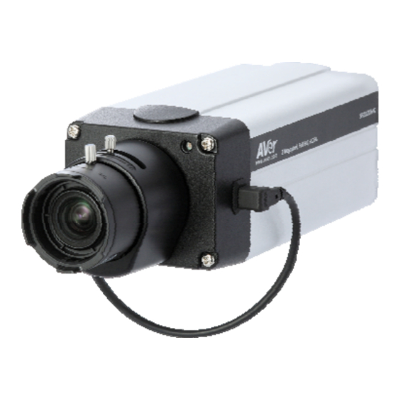
Page 6: Ip Camera Parts
F ro nt Pa ne l Built-in MIC Lens Light Sensor (fig. 1.1) Rear Pa nel RJ45 Ethernet Port DC 12V I/O Terminal Block Power LED Indicator SD card slot Video Out (10) Audio Out (11) Reset button Console (fig. 1.2) (10) MIC (11) DIP switch Note: The reset button will set all the configuration settings back to factory default. -
Page 7: Setting Up The Ip Camera
D e p lo yi n g N e tw ork Network Connection via Ethernet Switch Connect the RJ45 cable from the Ethernet switch to LAN (PoE) port of SF2121H-R. Ethernet Switch Connect the power adapter to DC12V port of SF2121H-R. -
Page 8: Power Over Ethernet Connection
Power over Ethernet Connection SF2121H-R is fully complied with PoE standard. It allows you to use PoE enabled switch or PoE injector to transmit data and power thru single Ethernet cable. PoE Enabled Switch Connection Diagram PoE Switch PoE Injector Connection Diagram... -
Page 9: Connecting The External Devices To I/O Terminal Block
Co nn ect ing the Exter na l D e vice s to I/O Te r min al B lo ck (1) Alarm Data In (2) Alarm Data Out (3) Power 12V support 200mA (4) Ground (5) RS-485 (+) (6) RS-485 (-) P ow er L ED L E D S ta t u s... - Page 10 Unscrew the CS-mount lens counterclockwise. Place one lens ring pad. Screw the CS-mount lens and connect the CS-mount lens cable to the socket. Check if the IP camera can display proper image. If not, repeat step 3 and 4 to add the next ring. If all the rings are used up and still the IP camera cannot display proper image.
-
Page 11: Focusing The Ip Camera With Bnc Monitor
Screw the CS-mount ring to the CS- mount lens. Screw the CS-mount lens clockwise back. Unscrew a little and plug the CS- mount lens cable to the socket. Repeat this till the IP camera display the image properly. Once the IP camera has detected the image, use the L-type hex wrench slightly secure bolt underneath the IP camera. -
Page 12: Setting Up The Ip Camera Over The Internet
IPCam Utility software in the CD to search the IP camera in the network. 1. Make sure the DIP switch behind the IP camera is set to DHCP. 2. Install the AVer IPCam Utility software. 3. Run the IPCam Utility. -
Page 13: Using Non-Dhcp Server/Router Network
settings and then click [Apply]. This will change the setting and rescan the network again. 6. The IE browser will open and direct you to IP camera login page. This requires IPViewer.ocx to run. If the IE ActiveX warning message appears, click to allow running the add-on. - Page 14 Panel > Network Connections > right click on the connection to change > option to TCP/IP or TCP/IPv4 Properties. 3. Type the default IP http://192.168.1.168 in the IE address bar. 4. You will be directed to IP camera login page. This requires IPViewer.ocx to run. If the I ActiveX warning message appears, click to allow running the add-o n.
-
Page 15: Configuring The Internet Explorer Security Setting
ActiveX is required to view and access the IP camera. High Internet Explorer security setting may prevent you from installing the ActiveX. If you are unable to view the IP camera, you may need to install ActiveX or change the security setting. To ch an ge t he In ter ne t Exp lorer Secu r it y Set ting 1. -
Page 16: Using The Ip Camera Browser Interface
4. Go to ActiveX control and plug-ins and change all Disable setting to Enable or Prompt. Then click [OK]. You will now be prompt to install ActiveX and view the IP camera. The admin have the full access to the IP camera browser interface. The menu on the left, you can expand and navigate to access all the features. - Page 17 Name Function (1) Language Select the browser interface langua (2) Video screen Change the video screen display. Display the actual video pixel size. Display the video screen in compact size. Display the video on the entire screen. Press ESC to exit full screen mode.
-
Page 18: Using Media Player To View Ip Camera
Some media player support viewing network streaming such as VLC media player. Use the format below to view your IP camera. The WWW.XXX.YYY.ZZZ below represents the IP address. RTSP://WWW.XXX.YYY.ZZZ:554/live_st1 -->for Stream 1 RTSP://WWW.XXX.YYY.ZZZ:554/live_st2 -->for Stream 2 (if stream 2 is enable) RTSP://WWW.XXX.YYY.ZZZ:554/live_st3 -->for Stream 3 (if stream 3 is enable) S ys t e m >... -
Page 19: To Upgrade The Ip Camera Firmware
Name Function (1) Export Settings Backup all the configuration settings. (2) Import Se ttings Restore or replace the cu rrent settings with the backup file. (3) Reboot Restart the IP camera. (4) Reset Set all the configuration settings back to default except the user management and network settings. -
Page 20: System > General > Date & Time
S ys t e m > G ene ra l > D a t e & Tim e In the Date & Time tab, admin can manually set the date and time setting or synchronize it with the Internet time server or the computer date and time setting. This is used to record the time whenever there is a significant occurrence listed in system log and is also used in event scheduling. -
Page 21: System > General > System Log
S ys t e m > G ene ra l > S ys t e m L og In the System Log, admin can view and search the significant event occurred in the IP camera. S ys t e m > U s er Ma nag e men t In User Management, only admin level is authorized to create, delete, and edit account to connect to the IP camera and configure the client connection setting. -
Page 22: To Delete Or Edit A User Account
User Type Access rights Admin Can access all the configuration pages Operator Can preview live image, modify and adjust certain settings except System > General, User Manag ement, and Network; and SD Card > Management. As for the I/O Control, admin could enable/disa allowing operator to access it. -
Page 23: System > User Management > Connection
S ys t e m > Us er Ma nag e men t > Co nn ect ion In Connection tab, admin can set the total number of user to access the IP camera, and filter the IP address to allow or deny accessing the IP camera. Name Function (1) Http Connection... -
Page 24: System > Network
Name Function corresponding subnet mask to be filtered. Range – assign a range of IP address to be filtered. 3. Save to add the created data in the filter list or Cancel to void the operation and exit. S ys t e m > N e tw ork In this section, only admin level is authorized to set up the Network settings. -
Page 25: System > Network > Server
Name Function (3) Network Type Select the type of IP camera Network connection. DHCP – select this option to automatically obtain an IP add ress from the DHCP server, whenever the IP camera is connecte d to the network. You can use the IP camera UPnP Discovery software in the CD to easily setup the IP camera network. -
Page 26: System > Network > Ddns
S yst em > Netw ork > DDN S In DDNS tab, you can configure the dynamic domain name service setting. DDNS is a service that provides fixed host and domain name for the IP camera with dynamic IP address. It automatically updates the new IP address to the dynamic server of the domain name. -
Page 27: System > Network > Others
S ys t e m > N e tw ork > Ot he rs In Others tab, you can configure the enable/disable the UPnP setting. If your router does not support UPnP function, you can enable the UPnP forwarding and set the port mapping. S ys t e m >... -
Page 28: System > Image > Preference
Name Function (1) Time Stamp Select the location of the Time Stamp. Click the checkbox to enable/disable display the date and time stamp. (2) Title Stamp Select the location of the Text Title. Click the checkbox to enable/disable display the text title. (3) Title Text Enter the title text, e.g. -
Page 29: System > Image > Exposure
S ys t e m > Ima ge > Exp os ur e In Exposure tab, you can set the exposure zone, exposure mode, and calibrate the DC Iris. After completing the setting, click Save to apply the new setting and Cancel to keep the old setting. -
Page 30: System > Image > Advanced
S ys t e m > Ima ge > A dva n c ed In Advanced tab, you can configure the Wide Dynamic Range, Denoise, IR-Cut Filter, and B/W image at night. After completing the setting, click Save to apply the new setting and Cancel to keep the old setting. -
Page 31: System > Image > Privacy Mask
Name Function (4) B/W image at night Select to enable/disable switching to B/W during night mode. (5) Night mode priority Select the one you want to prioritize during night mode image quality or frame rate. S ys t e m > Ima ge > Pr iva c y M a s k In Privacy Mask tab, you can enable 3 privacy masks. -
Page 32: System > Audio
Name Function (1) Stream Type Select to transmit single or simult aneous multiple streams of 2 or 3 videos. (2) Codec Type Select the type of video compression codec. (3) Resolution Select the video size. (4) Stream On each stream, set the frame rate, bitrate and rate control setting. -
Page 33: System > Sd Card > Management
Name Function (1) Audio Select to enable/disable the IP camera built-in mic and mic port. (2) Internal/Externa Select to boost up the internal/external mic gain or set to MIC gain normal. (3) Audio Codec Select the audio protoc ol, algorithm, and audio bit rate. G.711 –... -
Page 34: System > Sd Card > Filesearch
S ys t e m > S D C a rd > F i l e Sea rc h Use this to search the captured image in the SD card. Ap p lic at ion > Mo tion De tect ion Both admin and operator levels can specify up to 3 areas on the screen to monitor the motion. -
Page 35: Application > Patrol
assesses the changes in pixel thru percentage. The motion detection will activate when the Monitor level reaches the defined percentage. 5. Click Save to apply the new setting and Cancel to keep the old setting. A p p l ic at ion > P at r o l Both admin and operator levels can customize the Patrol setting. -
Page 36: Event
5. Set the dwelling time for how long you want to stay in the preset target area. Double- click and enter the time. Then click OK or press enter to apply the changes. 6. Click to delete the selected preset location in the Portal Locations list and arrange the patrol order. -
Page 37: To Setup The Event
To Setup the Event 1. Click Event. 2. On the time table, click-drag to select from what time to what time to specify the period of the event. 3. Type a name for the Event setti ng. One word only and no special character. 4. -
Page 38: Status Information
Snapshot and System log support sending the file thru Mail, and storing in FTP, NAS or SD card. You can enable multiple options to send and save the captured im age. Video Clip supports storing in FTP, NAS or SD card. You can only select one storage option to save the video file. - Page 39 Auto Iris DC Iris Viewing angle Horizontal 42.2°~105.4° Vertical 23.8°~57.9° Diagonal 48.3°~123.1° Lens (Optional*) Lens type Vari-focal lens (CS mount) F/no F/1.2 Focal Length F=3.1~8mm Viewing angle 105.4°(W )~42.2° 3-axis bracket adjustment angle Video Compression H.264/MPEG-4/MJPEG H.264 1920 x 1080 Max.
-
Page 40: Federal Communications Commission Statement (Class B)
Ethernet Ethernet (1 0/100 Base-T), RJ45 connector Security Password protection Users up to 10 users simultaneously Alarm Alarm Triggers Mail, FTP, SD-card, Terminal block (DI/DO), Samba Interface Digital input/output Built-in storage option SD card slot External microphone input supported External Audio output supported RS-485 supported... -
Page 41: Class B (Emc)
© 2012 AVer Information Inc. All rights reserved. All rights of this object belong to AVer Information Inc. Reproduced or transmitted in any form, or by any means without the prior written permission of AVer Information Inc. is prohibited. AVer Information Inc. - Page 42 You as the original purchaser. Except for the foregoing, the Product is provided “AS IS.” In no event does AVer warrant that You will be able to operate the Product without problems or interruptions, or that the Product is suitable for your purposes. Your exclusive remedy an the entire liability of AVer under this paragraph shall be, at AVer’s option, the repair or replacement of...
Need help?
Do you have a question about the SF2121H-R and is the answer not in the manual?
Questions and answers