
Subscribe to Our Youtube Channel
Related Manuals for Barco DP2K Series


Summary of Contents for Barco DP2K Series
- Page 1 Communicator Touch Panel User guide For DP2K & DP4K series R59770488/05 06/06/2012...
- Page 2 Barco nv Entertainment Division Noordlaan 5, B-8520 Kuurne Phone: +32 56.36.82.11 Fax: +32 56.36.883.86 Support: www.barco.com/esupport Visit us at the web: www.barco.com Printed in Belgium...
-
Page 3: Software License Agreement
Changes Barco provides this manual ’as is’ without warranty of any kind, either expressed or implied, including but not limited to the implied warranties or merchantability and fitness for a particular purpose. Barco may make im- provements and/or changes to the product(s) and/or the program(s) described in this publication at any time without notice. - Page 4 This software and the accompanying files are sold “as is” and without warranties as to performance or mer- chantability or any other warranties whether expressed or implied. In no event shall Barco be liable for damage of any kind, loss of data, loss of profits, business interruption or other pecuniary loss arising directly or indirectly.
-
Page 5: Table Of Contents
Table of contents TABLE OF CONTENTS 1. Introduction ..................7 General introduction ................... 7 About this manual .. - Page 6 Table of contents PCF......................45 3.5.1 Activate a PCF file..
- Page 7 Table of contents 4.3.2.2 Start self test ..................103 4.3.2.3 Read and Save log file .
- Page 8 5.9.4.7 Backup clone TI board only..............175 5.9.4.8 Backup clone Barco controller only ............177 5.9.5 Restoring a clone file.
- Page 9 Table of contents 7.3.2 About custom settings ................225 7.3.3 Load custom settings ..
- Page 10 Table of contents Index ....................277 R59770488 COMMUNICATOR TOUCH PANEL 06/06/2012...
-
Page 11: Introduction
General introduction Configuration tool A uniquely powerful and easy to use configuration tool for the Barco cinema projector. This touch panel provides all the necessary tools and only those tool necessary for the connected projector to setup and control this projector. A comprehensive array of easy to access menu pages provide the projectors digital input, output and screen display via a combination of simple buttons and displays. -
Page 12: About The Start Up
1. Introduction Note, gives extra information about the described subject. Tip, gives extra advice about the described subject. Images given in the manual are used as illustration. The content of the image can be slightly different with the real image on the screen, e.g. version numbers, projector name, installed modules, etc. . Typography: •... - Page 13 1. Introduction Display areas Image 1-1 Overview display Projector name, this name can be changed in Installation → Communication or with Projector Toolset Status indication LEDs. Custom logo, this logo can be changed with Projector Toolset. Configuration and control pane, active area to make selections and execute controls. User selection button.
-
Page 14: Projector Status Indication
1. Introduction Projector status indication Indication When the projector has errors or warning an error or warning symbol is added on the right bottom corner of the main window, next to the clock. That symbol can have 2 different states: •... -
Page 15: Touch Panel Keyboard
1. Introduction Image 1-3 Diagnostic companion The Diagnostic companion gives for a given situation, one or more possible solutions. If you want to pop-up the projector error message window every time an error or warning occurred, check the check box in front of Show this dialog automatically on new errors (4). Touch panel keyboard Overview Some controls need a user input. -
Page 16: Touch Panel Clock
1. Introduction Image 1-4 Touch panel keyboard Keyboard activation To display and activate the keyboard, tip on the keyboard button at the right corner from the bottom. The activated keyboard is displayed in the top part of the window. Deactivating the keyboard Tip the keyboard button to deactivate the keyboard. -
Page 17: Change User
1. Introduction 2. To change the month, tip on the left or right arrow button next to the current month indication (2a, 2b). 3. To select the day, tip on a day in the calender view (3). The background of the selected day changes to dark blue. 4. -
Page 18: Change Custom Logo
1. Introduction 3. Tip in the User password input field and enter the password (3). Note: Each character in the password is normally displayed as an asterisk. To display the real charac- ters, tip on the Display password button (3a). 4. -
Page 19: 1.10 Change Header
What is possible ? The header of the touch panel can be changed from the default header containing the custom cinema logo at the left and the Barco logo at the right to a graphical projector control window. How to change 1. - Page 20 1. Introduction Image 1-8 What is displayed ? Image 1-9 Graphical user interface Projector name Projector status Selected input Active files Lamp status Dowser status, when open dowser is next to the lamp, when closed, dowser is on the lamp Projected image, also holds if test pattern is displayed, yes or no.
-
Page 21: Controls
2. Controls 2. CONTROLS Overview • Presets • Test patterns • Service • Server Presets 2.1.1 Introduction Overview Depending on the setup, the user interface can have 5 preset pages. The first page contains 6 presets and is equal to the button on the projector itself. The next pages have each 8 presets. After the last preset is defined and there are still full blank preset pages, these pages will not be displayed in the user interface. -
Page 22: Activating A Preset
2. Controls 2.1.2 Activating a preset How to activate 1. Tip on the button next to the desired description. To activate a preset on another preset page, tip first on that preset page and then on the desired button. The macro behind the selected preset will be executed. A hourglass appears on the macro button. As an indication that the preset is activated, the button changes to blue. -
Page 23: Test Patterns
2. Controls Image 2-6 Dowser open/close button How to toggle the dowser 1. Tip on the dowser button to open or close the dowser. The status of the dowser is indicated by the button itself. When this button is blue, activated state, the dowser is closed. - Page 24 2. Controls Image 2-7 Change pattern selected Image 2-9 Loading test pattern Image 2-8 List of test patterns R59770488 COMMUNICATOR TOUCH PANEL 06/06/2012...
-
Page 25: Clear The Projected Test Pattern
2. Controls Image 2-10 Test pattern displayed When a convergence test pattern is on, color correction is bypassed. 2.2.2 Clear the projected test pattern Clearing any selected pattern 1. Click on Clear pattern. (image 2-11) A warning message will be displayed to indicate that any projector configuration changes made while a pattern was enabled are not saved, and will be lost when clearing the pattern (except resizing and masking). -
Page 26: Pattern Shortcuts
2. Controls Image 2-11 Clear pattern Image 2-12 Test pattern warning message Image 2-13 Removing test pattern 2.2.3 Pattern shortcuts The patterns behind the pattern shortcuts are always displayed in the RGB color space. When the projector is using a different color space at the moment the pattern is acti- vated, it will switch to the RGB color space. - Page 27 2. Controls How to select 10 predefined patterns can be quickly selected via the shortcuts. 1. Click on one of the 10 predefined pattern shortcuts. (image 2-14) The selected pattern will be displayed. The button becomes in the pressed state. The name of the pattern is filled out in Test pattern currently displayed.
-
Page 28: Service
2. Controls Image 2-16 Removing test pattern Service Overview • About the service settings • Lamp and lamp information • Light output mode 2.3.1 About the service settings To open the service settings Click on Service in the tab page pane. The following items are available: •... -
Page 29: Light Output Mode
2. Controls Current light output is only indicated when a CLO key is installed. Lamp power A histogram indicates the current value of the lamp power. The diagram indicates also the minimum and maximum limits for the lamp currently in use. The color of that histogram changes from green when lamp power is minimum to red when lamp power is maximum. -
Page 30: Server
2. Controls Target set up for CLO mode is lens dependent. CLO mode is only available when a valid CLO key is installed. How to setup 1. Click on the up down control of the spin box until the desired target value is reached. (image 2-19) 2. -
Page 31: Connection Properties
2. Controls Virtual Network Computing (VNC) is a graphical (GUI) desktop sharing system which uses the RFB (Remote FrameBuffer) protocol to remotely control another computer. It transmits the keyboard and mouse events from one computer to another, relaying the graphical screen updates back in the other direction, over a network. -
Page 32: Server Properties
2. Controls 2.4.2.2 Server properties Host name Image 2-21 Server properties When a DNS server is available, enter the host name of the server. When no DNS server is available, enter the IP address of the server. That address contains 4 octets with a maximum value of 255 and separated by a dot (.).. -
Page 33: Connection Options
2. Controls 2.4.2.3 Connection options Updating Image 2-22 Server properties, options View at client side will be updated with the time set in Check for updates every. Enter the scale value which must be used at the client side. Color pallet When 8-bit session is checked, only 8 bit color are transferred from the server to the client and the server display is shown as an 8 bit color display at the client side. -
Page 34: Connecting To Server
2. Controls Different encoding methods (compression methods) can be used to transfer data between the server and the client. When Auto is checked, the software checks the bandwidth of the connections and selects the best en- coding method for that moment. The Copy rectangle encoding can be used when the client already has the same pixel data elsewhere in its framebuffer. - Page 35 2. Controls Next click is Right Next tip done in the viewer window will be interpreted by the server as a right click click. Request screen The display in the viewer will be refresh on the client side. refresh R59770488 COMMUNICATOR TOUCH PANEL 06/06/2012...
- Page 36 2. Controls R59770488 COMMUNICATOR TOUCH PANEL 06/06/2012...
-
Page 37: Configuration
3. Configuration 3. CONFIGURATION Overview • About Configuration • Presets • Macro • Input • • Screen • 3D settings • Lens About Configuration Introduction The configuration page can be used to create or edit macros and to associate existing macros on presets. Next to that, the complete configuration from inputs over screen settings and lens adjustments can be set in the different configuration windows. -
Page 38: Removing An Association
3. Configuration 2. Browse to the desired file and tip on a file to select (3). Then tip Save (4). The selected macro is associated with the button (5). The name of the macro file is added next to button. Image 3-1 Macro association 3.2.3... -
Page 39: Activate Or Deactivate A Preset
3. Configuration Image 3-3 Edit existing macro 3.2.5 Activate or deactivate a preset How to activate 1. To activate a button, just tip on that button. The color of the button changes to blue. 2. To deactivate a button, just tip on a activated button. The blue button color changes to the standard gray color. -
Page 40: Edit Macro
3. Configuration 2. Scroll to the desired file and tip on that file to select (3). 3. Tip OK to activate the macro file (4). The macro file is activated and the name of the macro is indicated below the activation button (5). Image 3-4 Activate a macro 3.3.2... -
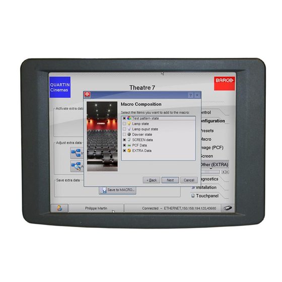
Page 41: Save To Macro
3. Configuration Image 3-5 Edit macro file 3.3.3 Save to macro What can be done? The current projector settings can be completely or selectively converted into a new macro or can be used to override existing information in a macro. The Save to macro procedure is a step by step procedure, guided by a wizard. - Page 42 3. Configuration The execute macro window opens. If you want to run the macro immediately, tip on Activate macro (13). 8. Tip on Finish to terminate the creation procedure (14). Image 3-6 Start up Save to macro wizard Image 3-7 R59770488 COMMUNICATOR TOUCH PANEL 06/06/2012...
-
Page 43: Input
3. Configuration Image 3-8 Finish macro creation Input Overview • Activate an Input file • Input settings, HD-SDI • Input settings, DVI • Input settings, Mediablock • Save to file • Save to Macro 3.4.1 Activate an Input file What is possible ? An input file can be activated via activate INPUT file. -
Page 44: Input Settings, Hd-Sdi
3. Configuration 3. Browse to the desired input file and tip on it to select (3). 4. Tip on OK (4). The selected input file is activated. The name of the file is indicated below the Activate INPUT file button. Image 3-9 Activate input file 3.4.2... - Page 45 3. Configuration 4. Select the source type The following sources are possible Standard HD-SDI board Quad-SDI board 2K-3D 2K-3D 2K-HFR 2K-HFR 2K 3D-HFR 5. Select the port to which the source is selected. The following ports are possible: For a standard HD-SDI board : A, B, A+B For a quad-SDI board: A, B, A+B, A+B+C+D 6.
-
Page 46: Input Settings, Dvi
3. Configuration 3.4.3 Input settings, DVI DVI-EDID Digital Visual Interface – Extended Display Identification Data DVI sources that are reported to the projector via the VESA E-EDID standard. These will be autodetected and displayed at the source format size, using standard processing. How to select 1. -
Page 47: Save To File
3. Configuration How to select 1. While in Configurator, click on Input. The Input overview is displayed. 2. Click on Input settings (1). (image 3-12) 3. Click on MED tab. 4. Select he correct parameters Mode Type Type parameter Color calibration 4:2:2 Progressive Single (default) -
Page 48: Save To Macro
3. Configuration 3. Select a file to overwrite (3a) or tip in the input field next to Filename and enter a name (3b). 4. Tip Save (4). Image 3-13 Save to file 3.4.6 Save to Macro What can be done ? The new input information can be saved in a new or existing macro file. -
Page 49: Pcf
3. Configuration Image 3-14 Save to macro Overview • Activate a PCF file • Active area selection and Aspect ratio • Save to file • Save to Macro 3.5.1 Activate a PCF file PCF File Projector Configuration File. This file is a file that will be delivered with each movie. It contains all data needed to display a certain movie as it is defined by the movie distributor. -
Page 50: Active Area Selection And Aspect Ratio
3. Configuration Image 3-15 Activate a PCF file 3.5.2 Active area selection and Aspect ratio Active Area The active area within a source frame equals the relevant movie information within the movie stream. E.g. : 1280 x 1024 movie can be mastered in a 1920 x 1080 stream. Only the 1280 x 1024 frame contains the relevant movie information. - Page 51 3. Configuration When Automatic is selected, the system assumes square pixels and calculates the aspect ratio based on the Active Area Size. When the image pixels are not squared, select one of the following aspect ratios: - 1.25 [5:4] - 1.33 [4:3] - 1.77 [16:9 HDTV] - 1.85 [Flat] - 2.39 [Scope]...
-
Page 52: Save To File
3. Configuration 3.5.3 Save to file What can be done? The new PCF information can be save in a new or existing PCF file. This file can be used to create or update macros. How to save 1. While in Configuration, tip on PCF. (image 3-18) The Image overview is displayed. -
Page 53: Screen
3. Configuration Image 3-19 Save to macro Screen Overview • Activate a SCREEN file • Resizing the image • Masking the image • Save to file • Save to Macro 3.6.1 Activate a SCREEN file Screen File Screen presentation configuration file. This file contains information about resizing, letterbox- ing, masking and lens factor. -
Page 54: Resizing The Image
3. Configuration The selected SCREEN file is activated. The name of the file is indicated below the Activate a SCREEN file button. Image 3-20 Activate a SCREEN file 3.6.2 Resizing the image Set lens anamorphic factor to 1.0 before starting resizing. AUTION Overview •... -
Page 55: Resizing With The Arrow Keys
3. Configuration As the projector project an image under an angle, the original image will be shown as trapezium. The image will be squared with the masking function by masking the shaded areas. 3.6.2.2 Resizing with the arrow keys Tip on to return to the initial values for he selected dots while resizing the image. - Page 56 3. Configuration Image 3-23 Short cuts to patterns (1) Full white pattern (2) RGB 12 bit alignment pattern (3) Framing uncorrected pattern (4) Focus green pattern Image 3-22 Resizing window Image 3-24 Resizing indication When leaving the Resize window without switching off the test pattern, this pattern will still be available for masking.
-
Page 57: Resizing With Direct User Input
3. Configuration As the resizing is best done on a test pattern, when finished, switch back to the normal image to check the resizing settings. After resizing set the anamorphic lens factor back to its original value. 3.6.2.3 Resizing with direct user input What can be done With direct user input it is possible to enter the resizing values with the keyboard. -
Page 58: Letterbox Function
3. Configuration Image 3-25 When leaving the Resize window without switching off the test pattern, this pattern will still be available for masking. As the resizing is best done on a test pattern, when finished, switch back to the normal image to check the resizing settings. - Page 59 3. Configuration Image 3-26 Example letterboxing enabled W and H are width and height of the resized area. R59770488 COMMUNICATOR TOUCH PANEL 06/06/2012...
- Page 60 3. Configuration • A : input source • - Resized area equals the maximum DMD size - The input image has a different aspect ratio from the resized area. - Full image is letterboxed (top and bottom) and centered within the resized area. •...
- Page 61 3. Configuration Image 3-27 Example letterboxing disabled W and H are width and height of the resized area. R59770488 COMMUNICATOR TOUCH PANEL 06/06/2012...
-
Page 62: Masking The Image
3. Configuration • A : input source • - Resized area equals the maximum DMD size - The input image has a different aspect ratio from the resized area. - Image is scaled up to fill resized area, requiring that some input data be discarded because it falls outside the resized area (dark transparent areas left and right). -
Page 63: Masking Via The Arrow Keys
3. Configuration shaded areas will be masked. Image 3-28 Masking indication 3.6.3.2 Masking via the arrow keys Click on to reset the masking for the selected button. Before starting masking, it is preferable to select a test pattern. How to mask? 1. - Page 64 3. Configuration 5. Move the selected button by tipping on the arrow keys of the keypad. The image will move in the direction of the clicked arrow. Yellow arrows on the interface image will indicate the direction. The values in the corner will change accordingly. 6.
- Page 65 3. Configuration Image 3-31 Masking the corners Image 3-32 Curve masking Press the Reset All button to reset the complete masking. As the masking is best done on a test pattern, when finished, switch back to the normal image to check the masking settings R59770488 COMMUNICATOR TOUCH PANEL 06/06/2012...
-
Page 66: Masking With Direct User Input
3. Configuration After masking set the anamorphic lens factor back to its original value. Do not forget to switch off the test patterns. 3.6.3.3 Masking with direct user input What can be done With direct user input it is possible to enter the masking values with the keyboard. Before starting masking, it is preferable to select a test pattern. - Page 67 3. Configuration The curve masking is applied to the image on the screen. 11.Press Close to return to the Screen menu. Image 3-33 Masking corners via direct input Image 3-34 Direct curve masking Press the Reset All button to reset the complete masking. R59770488 COMMUNICATOR TOUCH PANEL 06/06/2012...
-
Page 68: Save To File
3. Configuration As the masking is best done on a test pattern, when finished, switch back to the normal image to check the masking settings After masking set the anamorphic lens factor back to its original value. Do not forget to switch off the test patterns. 3.6.4 Save to file What can be done? -
Page 69: Save To Macro
3. Configuration Image 3-35 Save Screen data to file 3.6.5 Save to Macro What can be done? The new Screen information can be save in a new or existing macro file. How to save 1. While in Configuration, tip on Screen. The Screen overview is displayed. -
Page 70: 3D Settings
3. Configuration Image 3-36 Save Screen data to macro file 3D settings Overview • Activate 3D file • 3D settings • 3D settings, integrated color wheel • Save to file • Save to Macro 3.7.1 Activate 3D file How to activate a SCREEN file 1. -
Page 71: Settings
3. Configuration Image 3-37 Activate 3D file 3.7.2 3D settings Overview • About 3D projection • Start up the 3D settings • Frame rate multiplication • 3D Test pattern • 3D Controls 3.7.2.1 About 3D projection Summary Typical scenario for 3D projection: The left eye image data comes in over a HDSDI 24 p signal on port A on the projector. -
Page 72: Start Up The 3D Settings
3. Configuration Input selection Source selection 292 3D 3D settings Frame rate Multiplication 46:2 L/R Input Reference Use Line interleave where first line = Left second line = Right Set 3D Dark Time adjustment, 3D L/R Output Reference Delay and 3D L/R Output Polarity as needed. 3.7.2.2 Start up the 3D settings How to start up... -
Page 73: Test Pattern
3. Configuration For this system, M and N are defined as follows: • M is defined as the number of input frames of data (defined by input vertical sync) that are required to constitute a full frame of image data. This parameter is used to determine the “base” or “full” image frame rate for the input data, in the form: Base rate (Hz) = Input frame rate (Hz) / M. -
Page 74: Controls
3. Configuration How to check the complete setup 1. Tip on Activate to run the test pattern. A 3D test pattern generated on the interface board will be displayed. Alternating, the left and the right pattern will be displayed. For the best test pattern and to display the pattern for the left or the right eye: - set the frequency on 48 Hz - set frame rate multiplication on 4:2 - set 3D control, 3D L/R Input Reference on White Line Code True or Blue Line Code True. - Page 75 3. Configuration Setting Description Use GPI 2(polarity = true) Can be used for single stream inputs High : Left is Active Low : Right is Active Use GPI 2(polarity = false) Can be used for single stream inputs High : Right is Active Low : Left is Active Use input reference - frame sequence mode Use Active data port assignment (for dual port...
- Page 76 3. Configuration About Line interleave Image 3-42 Line interleave (1) Odd lines (2) Even lines The system alternates the lines between the left and the right eye. It starts with the first line containing the left eye information and the second line containing the right eye information. It continues in that way until a full frame is produced.
- Page 77 3. Configuration Delay 3D L/R Output Reference Data (displayed) Right Left Left Right Dark time Image 3-44 Output reference - displayed data Dark Time Adjustment Between switching the frames the image needs to be black the same time the external devices need to switch (external devices can be 3D Glasses, or polarizing filter).
-
Page 78: Settings, Integrated Color Wheel
3. Configuration 3.7.3 3D settings, integrated color wheel Overview • Start up of the advanced Integrated 3D settings • Integrated 3D settings (integrated color wheel) • 3D control 3.7.3.1 Start up of the advanced Integrated 3D settings How to start up 1. -
Page 79: Integrated 3D Settings (Integrated Color Wheel)
3. Configuration 3.7.3.2 Integrated 3D settings (integrated color wheel) 3D used/not used The 3D system uses an integrated color wheel in the light path of the projector. Before that color wheel can be used, the projector has to know if the projector is equipped with such a color wheel or not. Image 3-47 Filter status Check the check box in front of Use the integrated Dolby 3D to indicate that an integrated color wheel is... - Page 80 3. Configuration Image 3-48 3D controls Other operating modes are available but are not used for the moment. L/R input reference The Input Reference indicates which frame is Right and which frame is Left The following choices are possible: Setting Description 3D disabled no 3D images possible...
- Page 81 3. Configuration file with the L/R input reference to a value that is not 3D disabled, typically use active data port: Port A = Left, Port B = Right Dark Time Adjustment Between switching the frames the image needs to be black. For 3D applications, systems typically need a period of time where the image projected on the screen is black.
-
Page 82: Save To File
3. Configuration 3. Start e.g. with the left eye, adjust the delay until the white stripes disappear in the black column. Continue with the right eye and adjust the delay again. Image 3-49 Left eye delay test content Image 3-50 Right eye delay test content 4. -
Page 83: Save To Macro
3. Configuration Image 3-51 Save 3D data to file 3.7.5 Save to Macro What can be done? The new 3D data can be saved in a new or existing macro file. How to save 1. While in Configuration, tip on the double arrow downwards to open extra menu options and select 3D. (image 3-52) The 3D overview is displayed. -
Page 84: Lens
3. Configuration Image 3-52 Save to macro Lens Overview • Current lens • Activate Lens file • Lens shift and focus • Save to file • Save to macro 3.8.1 Current lens Overview To display the lens overview window, tip on the double arrow downwards and select Lens. Image 3-53 R59770488 COMMUNICATOR TOUCH PANEL 06/06/2012... -
Page 85: Activate Lens File
3. Configuration The current lens is indicated at the bottom of the lens overview pane. It is given with the article number and the full description of the lens. 3.8.2 Activate Lens file When the lens parameters are not selected, you will be prompted to select the correct lens that is used in conjunction with this projector. -
Page 86: Save To File
3. Configuration The Lens overview is displayed. 2. Tip on Lens Settings. (image 3-55) The lens adjustment settings window is displayed. 3. To shift the image, tip on the arrow buttons under Lens shift. Note: Use the pattern short cut keys at the right side to activate or deactivate an test pattern. The image can be moved left-right and up-down. -
Page 87: Save To Macro
3. Configuration Image 3-56 Save lens data to file 3.8.5 Save to macro What can be done? While in Configuration, tip on the double arrow downwards and select Lens. How to save 1. While in Configuration, tip on Lens. The Lens overview is displayed. 2. - Page 88 3. Configuration Image 3-57 Save lens data to macro R59770488 COMMUNICATOR TOUCH PANEL 06/06/2012...
-
Page 89: Diagnostics
4. Diagnostics 4. DIAGNOSTICS Overview • Actual diagnostics • History, logging • Tests • CineCanvas Actual diagnostics 4.1.1 Error messages Overview The scroll list gives an overview of the current errors inside the projector. The errors are given with an identifier (error number) and a description. -
Page 90: Active Files
4. Diagnostics Image 4-2 Diagnostics companion This diagnostic companion window gives for a given situation a possible solution. For a certain error number, multiple situations and solutions are possible and are helpful to solve the error. 4.1.2 Active files What is possible ? All current active files in the projector can be listed in a separate window. -
Page 91: Integrated Cinema Processor
4. Diagnostics Image 4-3 Active files 4.1.3 Integrated cinema processor For projectors with integrated Mediablock, only the ICP status and Active files buttons are available. Integrated Cinema Processor How to select 1. While in Diagnostics, tip on Actual. The Actual overview pane is displayed. 2. -
Page 92: Link Decryptor
4. Diagnostics The integrated cinema processor status opens (2). The following statuses are given: • General status System status System self test • Software status Load release package Install release package FMT mode operation: OK = normal mode, otherwise it can be in boot mode. ICP mode operation: OK = normal mode - Error messages - Hardware: installed ICP type... - Page 93 4. Diagnostics How to display the status 1. While in Diagnostics, tip on Actual. The Actual overview pane is displayed. 2. Tip on Link decryptor. (image 4-5) The link decryptor status is displayed. The following status are given: • General status System status System self test Marriage...
-
Page 94: Diagnostics About Other Electronics
4. Diagnostics Actions To clear a service door tamper only. Will only be accessible when the Service door tamper is active. Tip Yes to clear the tamper. Image 4-6 Clear tamper 4.1.5 Diagnostics about other electronics Temperatures When one of the temperatures are out of specification, the indication will be in red. To see the maximum allowed temperature and the maximum warning and minimum warning temperature, click on the ’+’... -
Page 95: Projector Statistics
4. Diagnostics Image 4-7 Voltages When one of the voltages are out of specification, the voltage indication will be in red. To see the allowed limits and the warning limits, click on the ’+’ in front the item. The tree expands and shows for the selected item the values. -
Page 96: History, Logging
4. Diagnostics Image 4-8 Projector diagnostics Lamp run time Indicates the time the lamp was on since it first start up. History, logging Overview • ICP history logging • Projector log file • Version info • Diagnostic package 4.2.1 ICP history logging About the ICP history log file When something goes wrong on the ICP board, a logging of this failure is done in the ICP history log file. - Page 97 4. Diagnostics Image 4-9 ICP history log Save logging 1. Tip on Save (1). (image 4-10) A browser opens (2). 2. Select the storage location by tipping on one of the left icons or on the drop down box (3). Then browse to the desired location (4).
-
Page 98: Projector Log File
1. While in Diagnostics, tip on History. The History log selection menu is displayed. 2. Tip on Read history log file next to Projector (Barco). (image 4-11) The log file is downloaded via an FTP connection. R59770488 COMMUNICATOR TOUCH PANEL 06/06/2012... - Page 99 4. Diagnostics Image 4-11 Projector log file Save logging 1. Tip on Save (1). (image 4-12) A browser opens (2). 2. Select the storage location by tipping on one of the left icons or on the drop down box (3). Then browse to the desired location (4).
-
Page 100: Version Info
’+’ before an item to see more in detail the current software version. An asterisk is added next to the item which is different in the installed software and the package version. Version info is split up in a Barco part, package indicated next to the projector name, a TI part and a Link decryptor part. -
Page 101: Tests
4. Diagnostics Image 4-14 Diagnostic package Tests 4.3.1 Tests, video path Overview • Diagnostic companion, Video path start up • Display a HDSDI test pattern • Display a DVI test pattern • Display a ICP test pattern Test patterns used in the video path are adapted according the connected projector. 4K projector will use 4K test patterns, 2K projector will use 2K test patterns. -
Page 102: Diagnostic Companion, Video Path Start Up
4. Diagnostics 4.3.1.1 Diagnostic companion, Video path start up How to start up 1. While in Diagnostics, tip on Tests The Tests overview page is displayed. 2. Tip on Video path. (image 4-15) The Diagnostic companion window opens. Image 4-15 Diagnostic companion window for videopath 4.3.1.2 Display a HDSDI test pattern... -
Page 103: Display A Dvi Test Pattern
4. Diagnostics The selected test pattern is started on the HDSDI board and the video path cab be tested. The number of error counts since the last clear action are indicated in the table (7). This table is not updated if continuous update is not checked. -
Page 104: Display A Icp Test Pattern
4. Diagnostics 5. Tip Close (6). The selected test pattern is started on the DVI board and the video path cab be tested. The number of error counts since the last clear action are indicated in the table (7). This table is not updated if continuous update is not checked. -
Page 105: Tests, Self Tests
4. Diagnostics Image 4-18 ICP video path test 4.3.2 Tests, self tests 4.3.2.1 Self test, activation How to activate 1. While in Diagnostics, tip on Tests (image 4-19) The Tests overview page is displayed. 2. Tip on Self Test (1). A self test message appears (2) to make sure that no show is running while starting up the self test procedure. - Page 106 4. Diagnostics Image 4-19 Diagnostic companion, self test Name view - article number view The self test window can contain module names or module article numbers. To switch from one to the other, tip on the drop down menu next to Hardware identification and select the desired view. R59770488 COMMUNICATOR TOUCH PANEL 06/06/2012...
-
Page 107: Start Self Test
4. Diagnostics Image 4-20 Self test window, views 4.3.2.2 Start self test About self tests It is possible to select one or more individual tests or to select all tests at once. The status column indicates the status of the test. The result, number of fails and passes, is indicated next to Result. How to start 1. -
Page 108: Read And Save Log File
4. Diagnostics Image 4-21 Self test selection Image 4-22 Self test result 4.3.2.3 Read and Save log file What can be done ? The results of the tests are written in a log file. This log file can be consulted and saved. How to read and save the log file 1. -
Page 109: Reboot Actions, Projector
4. Diagnostics Image 4-23 Save self test log file 4.3.3 Reboot actions, projector What can be done? The complete projector can be rebooted. While rebooting, the image will be lost and the connection with the projector is broken. How to reboot 1. -
Page 110: Cinecanvas
4. Diagnostics Image 4-24 Projector reboot CineCanvas Overview • Introduction • Server overview interface • Timeline Control • Subtitle Control • Metadata Control 4.4.1 Introduction Overview The projectors are equipped with the possibility to process Subtitle and metadata information coming from a server. -
Page 111: Server Overview Interface
Overview of the layout Image 4-26 Overview interface In order to simulate a server triggering the projector’s subtitling mechanism, or to check if a server is configured as it should be, Barco provides an interface as shown above. R59770488 COMMUNICATOR TOUCH PANEL 06/06/2012... -
Page 112: Timeline Control
4. Diagnostics The following is visualized from left to right and from top to bottom : • time code, internal or external • time code itself • Status, running or not running • Subtitle status, enables or disabled • Subtitle file location •... -
Page 113: Input Frequency
4. Diagnostics 4.4.3.2 Input frequency Why necessary The projector needs to know the frequency of the input signal presented to the projector so that it can calculate internal synchronization parameters. How to select 1. Tip on one of the radio buttons in the Input frequency field. (image 4-28) Possible choices : - 23.98 Hz - 24.00 Hz... -
Page 114: Control
4. Diagnostics What is the purpose While the time code is running, the timeline can be adjusted by adding time to current time or by subtract- ing time from the current time. With these small corrections, it is possible to adjust small misalignments between the spoken text and the subtitling. -
Page 115: Steps To Be Taken For Subtitle Control
4. Diagnostics 4.4.4.1 Steps to be taken for subtitle control Overview 1. With Subtitle enable not checked, fill out first the subtitle server address. 2. Set up the subtitle file. 3. Set up the “time to live”. 4. Activate the subtitling 4.4.4.2 Access to the subtitle control How to get access... -
Page 116: Time To Live (Ttl)
4. Diagnostics Image 4-32 Subtitle file input 4.4.4.4 Time to live (TTL) Why used The TTL (Time to live) is a countdown time-out used to prevent subtitles from being left on the screen through loss of communication. The server or touch panel will continuously ask for the subtitle status. As long as the ’time to live’ counter has not been expired and the subtitle status command is executed, this TTL value will be reset to its original value set in the TTL interface. -
Page 117: Subtitle Control Activation
4. Diagnostics 4.4.4.5 Subtitle Control activation How to activate 1. Check the check box in front of Subtitle enabled. (image 4-34) Note: This is only possible when a correct path (server address + filename) to the subtitle file are filled out. -
Page 118: Steps To Be Taken For Metadata Control
4. Diagnostics Content of the metadata info Metadata Control from a server: • Provides projector setup instructions without operator action • Contains instructions provided by content creator (PostProduction) • Information sent from server to projector at start of the movie •... -
Page 119: Metadata File
4. Diagnostics 4.4.5.4 Metadata file How to select 1. Tip in the input field below Selected Metadata control XML file. (image 4-36) 2. Enter the IP address of the server followed by a slash (’/’) and the name of the XML file. input mask : http:// IP address / filename.xml Image 4-36 Metadata server and file setup... -
Page 120: Metadata Control Activation
4. Diagnostics Image 4-37 Time to live 4.4.5.6 Metadata Control activation How to activate 1. tip the check box in front of Metadata enabled. (image 4-38) Note: This is only possible when the path (server address + filename) to the metadata file are filled out. Note: An indication in the Setup Control interface will be added. -
Page 121: Installation
5. Installation 5. INSTALLATION Overview • Communication • Lamp, light output and calibration • Lamp alignment • Lamp information • Lamp recovery • Linked lamp output • Color calibration • Automation • Advanced settings Communication Overview • Ethernet Connections • Get overview current Ethernet addresses •... - Page 122 5. Installation Default Gateway A router that serves as an entry point into and exit point out of a network. For example, a local network (LAN) may need a gateway to connect it to a wide area network (WAN) or to the Internet.
-
Page 123: Get Overview Current Ethernet Addresses
How to set up 1. While in Communication, tip Edit (1) button under Projector IP address. (image 5-1) The Edit the Barco IP address window opens (2). 2. Tip in the hostname input field and enter the desired name (3). -
Page 124: Assign An Ethernet Address Via Dhcp
How to set up 1. While in Communication, tip Edit (1) button under Projector IP address. (image 5-2) The Edit the Barco IP address window opens (2). 2. Check the check box next to Obtain an IP address automatically (DHCP) (3). -
Page 125: Manually Assign An Ethernet Address
How to set up 1. While in Communication, tip Edit (1) button under Projector IP address. (image 5-3) The Edit the Barco IP address window opens (2). 2. Check the check box next to Use the following IP address (3). - Page 126 5. Installation Image 5-3 Projector IP address, manually assign The Touch panel’s IP Address MUST be within the same subnet as the projector’s IP Address in order for communication to be possible. This requires checking the Touch panel’s and projector’s Subnet-Mask settings IP address examples First example •...
-
Page 127: Lamp, Light Output And Calibration
5. Installation Third example • Touch panel IP Address : 192.168.200.1 • Touch panel Subnet Mask : 255.255.255.0 • Projector IP Address : 192.168.100.2 • Projector Subnet Mask: 255.255.255.0 Result : No communication possible. Touch panel address is not in the subnet range of the projector’s IP address. -
Page 128: Lamp And Lamp Information
5. Installation Image 5-4 Start up light output/calibration window 5.2.2 Lamp and lamp information Current light output The current light output is indicated in FootLambert. Image 5-5 Current light output It indicates also in which mode the projector is working. Lamp power/current A histogram indicates the power value / current value of the lamp. -
Page 129: Lamp Output Mode
5. Installation 5.2.3 Lamp output mode 5.2.3.1 Target set up for Normal mode How to setup 1. Tip on the radio button next to Normal Mode. The mode selection pane changes to the Normal mode parameters (image 5-6) 2. Adjust with the slide bar until the desired lamp power is obtained. tip on the up down control of the spin box until the desired value is reached tip inside the text box and enter a new value with the keyboard. -
Page 130: Light Sensor Calibration
5. Installation Image 5-7 Light output, CLO mode Image 5-8 5.2.4 Light sensor calibration What can be done ? Depending on the used screen type, flat, scope, flat3D or scope3D, a different file has to be loaded for the light sensor before starting the calibration. By loading a different file the light output can be made equal for both screen types. -
Page 131: Lamp Alignment
5. Installation Image 5-9 Light sensor calibration Create new calibration file 1. Enter the footlambert value to be used in the new calibration file (5). 2. Tip Save (6). A browser window opens. Enter a file name and tip Save. The new file is ready to be used as LSC file. -
Page 132: Lamp Light Output History
5. Installation also necessary to reach the maximum light output. Depending on the used lamp house, these alignments can be done manually on the lamp house itself or motorized by tipping on the motor keys in the lamp alignment menu. 5.3.2 Lamp light output history Visual presentation... -
Page 133: Automatic Lamp Alignment
5. Installation 5.3.3 Automatic lamp alignment What can be done ? Both automatic lamp alignment functions adjust the lamp in either the Z-axis or in all axis to obtain the maximum light output. Wait until the process stops or interrupt the processes by stopping it manually. How to fast align 1. -
Page 134: Manual Lamp Alignment
5. Installation 2. Tip on Start fine alignment (all axis). The software starts with the alignment. The intermediate light output results can be followed on the preview graph. The alignment can take a while. Once the light output reaches its maximum value the process stops automatically. -
Page 135: Lamp Information
5. Installation Lamp information About the information The lamp information window displays read only information about: Run time in hours Run time since first start up of the lamp or since the last reset. Remaining run Remaining run time that the lamp can be used without risk of damaging the time in hours projector. - Page 136 5. Installation click on Select (5b) to display a list of possible article numbers (6). Select a article number (7) and click OK (8). The software will check if the entered article number is a valid number (9). 4. Fill out the serial number of the lamp (10). 5.
- Page 137 5. Installation 2. To get history of the used lamps, click from history (3). The Reset lamp history selection window opens (4). 3. Click on Select (5) to display a list of possible lamps (6). 4. Select the desired lamp (7) and click OK (8). The article number and serial number of the selected lamp is added to the Reset lamp parameters window (10).
- Page 138 5. Installation Image 5-15 Reset lamp info, used lamp R59770488 COMMUNICATOR TOUCH PANEL 06/06/2012...
-
Page 139: Lamp Recovery
5. Installation Lamp recovery About lamp recovery When there was an external power failure and the power is coming up again, the projector lamp starts up again in the same state as before the power failure. The projector software has to know if the projector must remember its recovery settings. About the use of an UPS system When the projector is connected to an UPS system the electronics remains powered during an external power failure. -
Page 140: Set Up Of The Master Projector
5. Installation 5.6.2 Set up of the master projector How to setup 1. Click on Linked lamp output (1). (image 5-17) The Linked Lamp output window opens (2). 2. To set the projector as master, check the check box in front of Is master projector (3). 3. -
Page 141: Color Calibration
5. Installation Image 5-17 Linked lamp output setup Color calibration Overview • Introduction to Color Calibration • Color path selection • Color Correction Process • Color Measuring • Select target colors • Verifying the colors after correction 5.7.1 Introduction to Color Calibration Overview The color coordinates for the projected primary colors must be measured on the screen. -
Page 142: Color Path Selection
5. Installation of the glass between the projection booth and the theatre and even the projected colors are different from setup to setup. These measured color coordinates are references for the projector and will be entered so that the projector knows how its colors are projected on the screen. - Page 143 5. Installation A loading color test pattern message will be displayed. After a while, the selected color will be projected without any color correction on the screen. The selected input fields of that specific color becomes white (4). 4. Measure the color coordinates for that specific color. When single was selected, measure the x and y coordinate and enter in the white input field.
- Page 144 5. Installation Image 5-18 Startup color gamut measurement Image 5-19 Color gamut, Color selected R59770488 COMMUNICATOR TOUCH PANEL 06/06/2012...
- Page 145 5. Installation Image 5-20 Save coordinates to file R59770488 COMMUNICATOR TOUCH PANEL 06/06/2012...
-
Page 146: Select Target Colors
5. Installation Image 5-21 Save coordinates to file 5.7.5 Select target colors For Color path selection “Single” 1. Tip on Select target colors (1) (image 5-22) The Target Color Gamut selection window opens. 2. Tip Browse and select the desired TCGD file 3. - Page 147 5. Installation Image 5-22 Select target colors, single color path For Color path selection “Dual” 1. Tip on Select target colors (1) (image 5-23) The Target Color Gamut selection window opens. 2. If you want to use the same file for both eyes, make sure that the check box before Adjust left eye separately is unchecked (3).
-
Page 148: Verifying The Colors After Correction
5. Installation Image 5-23 Select target colors, dual color path 5.7.6 Verifying the colors after correction AUTION Set anamorphic factor to 1.0 before verifying the colors after correction. Overview The color coordinates of the projected image after correction can be verified by measuring the coordinates on the screen again. - Page 149 5. Installation A remove color pattern message will be displayed. (image 5-25) The color pattern is removed. 6. Set the anamorphic lens factor back to its original value. Image 5-24 Verify colors Image 5-25 Remove color test pattern R59770488 COMMUNICATOR TOUCH PANEL 06/06/2012...
-
Page 150: Automation
5. Installation Automation Overview • General purpose inputs configuration • Event GPO configuration • GPO status 5.8.1 General purpose inputs configuration What is possible This interface enables the user to configure the automation system that is present inside the projector (standard GPI configuration). -
Page 151: Event Gpo Configuration
5. Installation Image 5-26 GPI configuration 5.8.2 Event GPO configuration What can be done ? When an event happens, e.g. lamp power on, a GPO can be set in certain state. The output of this GPO can be used to trigger processes in the theatre or control room. GPO 1, GPO 2 and GPO 3 are reserved and cannot be used by the user. - Page 152 5. Installation The GPO association window opens (4). 4. Tip on the drop down box next to GPO and select the desired GPO (5). 5. Tip on he drop down box next to GPO action and select the desired action (6). The selected action is the action the GPO will take when the associated event happens.
-
Page 153: Gpo Status
5. Installation Warning : show can continue but a technical intervention will be necessary to prevent an error. Notification : no show stopping event, but a maintenance of the projector will be necessary in the very near future. 5.8.3 GPO status What can be done ? With the GPO status tab, the automation systems triggered by a GPO can be tested. -
Page 154: Set Up Of The Icp Clock
5. Installation Image 5-29 Overview • Set up of the ICP Clock • Set up of the Link Decryptor Clock • File manager • File management, cloning • Restoring a clone file • Lens selection • Lens homing and return •... - Page 155 5. Installation 6. To set the time, hour, minutes and seconds, tip on the up down control of the corresponding spin box until the correct value is displayed (7) tip in the input field, select the current value and enter the new value with the simulated keyboard. 7.
- Page 156 5. Installation Image 5-31 ICP clock via touch panel To set the clock to UTC/GMT time using NTP 1. Tip on Internal clock (1). (image 5-32) 2. ICP tab is opened by default. 3. Tip on the radio button before UTC/GMT using NTP (4) 4.
-
Page 157: Set Up Of The Link Decryptor Clock
5. Installation Image 5-32 ICP clock using UTC/GMT based on NTP 5.9.2 Set up of the Link Decryptor Clock This clock must always be set to UDC GMT. AUTION Maximum allowed deviation per year is 15 minutes. What can be done ? The link decryptor clock can be set to Touch panel time or to a user defined time. - Page 158 5. Installation How to set the clock While in the Advanced tab page: 1. Tip on Internal clock (1). (image 5-33) The Projector internal clock window opens. 2. Tip on Link decryptor tab (3). 3. Make your choice about the clock synchronization source (4) Select Touch panel time to synchronize with the touch panel time.
-
Page 159: File Manager
5. Installation Image 5-33 Link decryptor clock 5.9.3 File manager Overview • Introduction • Activating the file manager • Changing the view • Create new local folder • Refresh folder • Delete a file or folder • File upload • File download R59770488 COMMUNICATOR TOUCH PANEL 06/06/2012... -
Page 160: Introduction
5. Installation 5.9.3.1 Introduction Overview The touch panel makes use of an internal “disk chip”. This chip contains a file system that can handled in a similar way as a file system on PC. That allows the touch panel to make use of files and directory structures similar to those found on a PC. -
Page 161: Changing The View
5. Installation Image 5-34 File manager startup 5.9.3.3 Changing the view How to change the view for Projector files 1. Click on the drop down box just below Projector files and select the file type to be displayed. (im- age 5-35) The content of the list changes to the selected file type. - Page 162 5. Installation Mode Explanation LUT-CLUT Complex LUT lookup table. Projector Configuration File. This file is a file that will be delivered with each movie. It contains all data needed to display a certain movie as it is defined by the movie distributor. This file includes : •...
-
Page 163: Create New Local Folder
5. Installation Mode Explanation LENS Lens data file. Stores information about the lens adjustment in a typical setup. Light sensor calibration file Stores information about the calibration setting according the light output for a certain type of screen. Image 5-35 File selection How to change the view for Local files 1. -
Page 164: Refresh Folder
5. Installation 2. Browse to the location where to create a new folder. 3. Tip on the new folder icon (3). A New folder name window opens (4). 4. Enter a new name for the folder (5). 5. Tip on Apply (6). The new folder is created. -
Page 165: File Download
5. Installation How to upload a file 1. While the File manager window is open, tip on the drop down box and select the medium from where the file must be uploaded (1). (image 5-38, image 5-39) 2. Browse to the file and select the file (2). 3. -
Page 166: File Management, Cloning
• Full backup clone • Backup clone TI board only • Backup clone Barco controller only 5.9.4.1 Introduction Overview Users with multiple installations want to setup these installation in the same way. The same macros linked with the same buttons, etc. Therefore it is handy to setup one system and then to make a copy of the created macro files with all its links. -
Page 167: Start Up The Cloning
Full backup clone, clones every setting and file of the projector. • Full backup, backup clone TI board only. • Full backup, backup clone Barco controller only. 5.9.4.2 Start up the cloning How to start up 1. While in Installation, tip on Advanced. -
Page 168: Create A Basic Clone File
5. Installation 5.9.4.3 Create a Basic clone file What can be done ? All presets (macros) that are linked to a button and the files these presets are pointing to, together with its position on the keypad and/or touch panel are copied in a zip file. By default, projector specific files are not included in the zip file. - Page 169 5. Installation Image 5-42 Basic cloning Image 5-43 R59770488 COMMUNICATOR TOUCH PANEL 06/06/2012...
- Page 170 5. Installation Image 5-44 Image 5-45 R59770488 COMMUNICATOR TOUCH PANEL 06/06/2012...
-
Page 171: Create An Individual Preset Clone
5. Installation Image 5-46 Create clone file 5.9.4.4 Create an individual preset clone What can be done ? An individual preset (macro) and the files it points to can be cloned in a single clone file. Projector specific data is not included in the clone file. How to make an individual preset clone 1. - Page 172 5. Installation 3. Tip on Select (3). The file selection window opens. 4. Select the desired macro file out of the list (5) and tip on OK (6). The selected file is filled out in the selection window (6). Tip Next> to display an overview of the pointed files (7).
- Page 173 5. Installation Image 5-47 Clone individual preset R59770488 COMMUNICATOR TOUCH PANEL 06/06/2012...
- Page 174 5. Installation Image 5-48 Pointed files Image 5-49 Save to zip file R59770488 COMMUNICATOR TOUCH PANEL 06/06/2012...
-
Page 175: Create A Clone For A Typical File Type
5. Installation 5.9.4.5 Create a clone for a typical file type What can be done ? All files with a specific extension can be cloned in a clone file. For projector specific files, it is recom- mended to restore these files only on the same projector. How to make clone file 1. - Page 176 5. Installation Image 5-50 Clone typical file type R59770488 COMMUNICATOR TOUCH PANEL 06/06/2012...
-
Page 177: Full Backup Clone
5. Installation Image 5-51 File name selection 5.9.4.6 Full backup clone What can be done ? All settings and files in the projector are included in the full backup clone. This full backup clone can be restored on the same projector after a service action. How to make a backup clone 1. - Page 178 5. Installation A Browse window opens (6). Select the desired location and change the name. Tip OK. 6. Tip Create clone file (8). The clone file is created and stored on the selected location. 7. Tip Finish to terminate the backup procedure. Image 5-52 Full backup clone R59770488 COMMUNICATOR TOUCH PANEL 06/06/2012...
-
Page 179: Backup Clone Ti Board Only
5. Installation Image 5-53 File location selection 5.9.4.7 Backup clone TI board only How to clone a TI board 1. Check the radio button next to Create a clone file from the projector and tip on Next> (1). (image 5-54) 2. - Page 180 5. Installation Image 5-54 Cloning TI board R59770488 COMMUNICATOR TOUCH PANEL 06/06/2012...
-
Page 181: Backup Clone Barco Controller Only
1. Check the radio button next to Create a clone file from the projector and tip on Next> (1). (image 5-56) 2. Check the radio button next to Backup clone Barco board only and tip on Next> (2). List of all files and setup specific files is given. - Page 182 5. Installation Image 5-56 Cloning Barco controller files R59770488 COMMUNICATOR TOUCH PANEL 06/06/2012...
-
Page 183: Restoring A Clone File
5. Installation Image 5-57 File location selection 5.9.5 Restoring a clone file What can be done ? A clone file can be restored on the same projector or on a projector of the same type. If some components in the clone file already exist on the projector, then the software will ask to overwrite the existing file. How to restore 1. - Page 184 5. Installation Image 5-58 Restore clone file R59770488 COMMUNICATOR TOUCH PANEL 06/06/2012...
-
Page 185: Lens Selection
5. Installation Image 5-59 Restore clone file 5.9.6 Lens selection What must be done? The software must know the article number of the used lens in the current installation so that it can enter the correct lens parameters. How to enter the lens 1. -
Page 186: Lens Homing And Return
5. Installation Image 5-60 Lens selection 5.9.7 Lens homing and return About lens homing Homing the lens at any time is possible. After homing the lens returns to its original position. To access the homing function, select Lens parameters (1) to open the Lens parameters window (2). To home the lens at anytime, tip on Start (3). - Page 187 5. Installation Image 5-61 Lens homing Each time a lens is manipulated e.g. removed and inserted in a projector, or a new one is inserted, it needs to be homed and returned. The home and return functions homes the lens to a reference point and then returns it to its original po- sition.
-
Page 188: Refill Mode
5. Installation Image 5-62 Lens homing, last performed action 5.9.8 Refill mode Not for DP2K-12C projectors. What can be done ? When the cooling liquid has to be refreshed, the refill mode must be used to activate only the cooling pump. -
Page 189: Functionality Keys
5. Installation Projector returns to its normal operating conditions. Image 5-63 Refill mode 5.9.9 Functionality keys 5.9.9.1 Entering a single key SNMP Simple Network Management Protocol is the protocol governing network management and the monitoring of network devices and their functions. What can be done? Depending whether the option has been ordered, it is necessary to enter the key that has been delivered with the projector. - Page 190 5. Installation The option becomes available. Valid key is indicated next to the option. Image 5-64 Edit functionality key Delete a single key 1. While in the Advanced tab page, tip on Edit functionality keys (1). (image 5-65) The Functionality keys window opens with the current active keys (2). 2.
-
Page 191: Request For New Keys
This code contains the run time and the different keys necessary for your projector. This unique code can only be generated by Barco. Therefore, copy the UN code and send it to Barco. How to enter a new PM code 1. -
Page 192: 5.9.10 Snmp Configuration
5. Installation Image 5-66 Entering the PM code 5.9.10 SNMP configuration SNMP configuration start up 1. While in the Advanced tab page, tip on SNMP configuration. (image 5-67) The SNMP configuration window opens. R59770488 COMMUNICATOR TOUCH PANEL 06/06/2012... - Page 193 5. Installation Image 5-67 SNMP configuration Management System address to receive traps, add address 1. Tip on Add The IP address input window opens. 2. Enter the IP address of the management server. 3. Tip on OK to activate. The new server is added to the list of management servers. Trap resend interval Time between two traps to be send to the management servers.
-
Page 194: Security
5. Installation Service mode When service action should be done on the projector while the projector is running, check the radio button before Activated. SNMP alarms generated during the servicing time will be blocked so that no unneces- sary SMS or E-mails are sent to the control room. Once the servicing action is finished, check disabled again. -
Page 195: 5.9.11.2 Overview List Of Keys As Default User
5. Installation 5.9.11.2 Overview list of keys as default user How to get an overview list 1. While in the Advanced tab page, tip on Manage Security Keys (1). (image 5-69) The security window opens (2). 2. Tip on the show key list button (3). The key code window opens (4). -
Page 196: 5.9.11.3 Add Extra Key To The List
5. Installation Image 5-70 Image 5-71 List of available keys List without master key 5.9.11.3 Add extra key to the list Only root users are user holding the master key can add extra keys. How to add an extra key 1. -
Page 197: 5.9.11.4 Change Pin Code Of An Existing Key
5. Installation Image 5-72 Add new key to key list 5.9.11.4 Change PIN code of an existing key Can only be done as root user or when enter the security via the master key. How to change 1. Display first a list of all available keys. 2. -
Page 198: 5.9.12 Certificate
5. Installation Image 5-73 Change pin code 5.9.12 Certificate About certificates Before some productions are authorized to be displayed with a certain projector, the film distributor must distribute a key to the theatre owners. This key is associated with the projector certificate which will be available for the film distributors on a web portal. -
Page 199: 5.9.13 External Exhaust Fan Selection
5. Installation Image 5-74 Save certificate 5.9.13 External exhaust fan selection What is possible ? Eliminates possible generated warnings by the airflow switch. Only for DP2K-xxB series How to make the selection 1. While in the Advanced tab page, click on Miscellaneous (1). (image 5-75) The Miscellaneous window opens. -
Page 200: 5.9.14 Image Orientation
5. Installation Image 5-75 External exhaust fan selection 5.9.14 Image orientation What is possible ? The image orientation can be changed from front projection (default) to rear projection and from a normal image to an upside down image. How to change the orientation 1. - Page 201 5. Installation Image 5-76 Image orientation R59770488 COMMUNICATOR TOUCH PANEL 06/06/2012...
- Page 202 5. Installation R59770488 COMMUNICATOR TOUCH PANEL 06/06/2012...
-
Page 203: Maintenance
6. Maintenance 6. MAINTENANCE Overview • About smart maintenance • Maintenance info for specific maintenance type • Software upgrade, launch DC update companion • Software upgrade, projector or touch panel package • ICP software upgrade • Link decryptor software update •... -
Page 204: How To Display
6. Maintenance The following maintenances are possible: • Maintenance type A : interval 30 days (cleaning filters, check porthole for dust, dust on lens, etc.) • Maintenance type B : interval 90 days (clean air grids, check cooling liquid level, etc) •... - Page 205 6. Maintenance Image 6-2 Maintenance overview Image 6-3 Maintenance clearing R59770488 COMMUNICATOR TOUCH PANEL 06/06/2012...
-
Page 206: Software Upgrade, Launch Dc Update Companion
Enigma link decryptor software • Integrated Cinema Processor (ICP) software Download the corresponding update package from the secured Barco web site, https://my.barco.com a USB stick. This USB stick can then be plugged in on the touch panel. For Enigma link decrypor and ICP update package, unzip the package file into a new directory. For the projector software and the touch panel software package, unzipping is not possible. - Page 207 6. Maintenance Image 6-5 Launch DC update companion R59770488 COMMUNICATOR TOUCH PANEL 06/06/2012...
-
Page 208: How To Update
1. Launch the DC Update Companion as described in "Software upgrade, launch DC update companion", page 202. 2. Select package type. tip on the drop down box (1) and select Barco DC Package. (image 6-7) 3. Browse for the package file name. Tip on Browse (2) to open the Browser window (3). - Page 209 6. Maintenance If custom update (for advanced users) is selected, the wizard starts collecting the information (17) of the different software modules. 11.Select the modules to update (19) and tip Next to start the update (20). Image 6-7 Package file selection R59770488 COMMUNICATOR TOUCH PANEL 06/06/2012...
- Page 210 6. Maintenance Image 6-8 Barco release notes Image 6-9 IP selection R59770488 COMMUNICATOR TOUCH PANEL 06/06/2012...
-
Page 211: Icp Software Upgrade
6. Maintenance Image 6-10 Projector software update ICP software upgrade About updating ICP board The ICP board contains 2 slots to store software before this software can be installed. Therefore it is recommended to store the previous version of the software in a location and the current version in the other. - Page 212 6. Maintenance These 2 loaded versions make it possible to switch on an easy way between the current version and the previous one. How to upgrade 1. Launch the DC Update Companion as described in "Software upgrade, launch DC update companion", page 202.
- Page 213 6. Maintenance Image 6-11 ICP software update R59770488 COMMUNICATOR TOUCH PANEL 06/06/2012...
- Page 214 6. Maintenance Image 6-12 IP selection R59770488 COMMUNICATOR TOUCH PANEL 06/06/2012...
-
Page 215: Link Decryptor Software Update
6. Maintenance Image 6-13 Load and install software Link decryptor software update How to update 1. Launch the DC Update Companion as described in "Software upgrade, launch DC update companion", page 202. 2. Select package type. Tip on the drop down box (1) and select Enigma Link Decryptor Package . (im- age 6-14) 3. - Page 216 6. Maintenance 5. Enter the device IP address (10) or tip on Browse to open a device selection window (11). (image 6-15) Note: The IP of the connected projector is already filled out. When using the DC Update Companion as stand alone program, then this field is blank. 6.
- Page 217 6. Maintenance Image 6-15 IP selection Image 6-16 Startup update R59770488 COMMUNICATOR TOUCH PANEL 06/06/2012...
-
Page 218: Update Logging
6. Maintenance Update logging Installation logging When the software update is finished, a status window is displayed. This window is almost equal for all possible updates. Image 6-17 Status window. To show the log file, tip on Show log file. All information about the update process is logged in this log file. -
Page 219: Touch Panel
7. Touch panel 7. TOUCH PANEL Overview • Communication • User management • User access settings • Display properties • Change Language • Change units • Touch panel Diagnostics Communication 7.1.1 Assign an Ethernet address via DHCP to the Touch panel How to set up 1. -
Page 220: Manually Assign An Ethernet Address For The Touch Panel
7. Touch panel Image 7-1 Touch panel IP address via DHCP 7.1.2 Manually assign an Ethernet address for the Touch panel How to set up 1. While in Touch panel, Communication tab page, tip Edit (1) button under Touch panel network proper- ties (image 7-2) A message window opens if the check box never was checked in the past (2). - Page 221 7. Touch panel Image 7-2 Touch panel IP address, manually The Touch panel’s IP Address MUST be within the same subnet as the projector’s IP Address in order for communication to be possible. This requires checking the Touch panel’s and projector’s Subnet-Mask settings IP address examples First example •...
-
Page 222: Projector Connections, Communication Policy
7. Touch panel Third example • Touch panel IP Address : 192.168.200.1 • Touch panel Subnet Mask : 255.255.255.0 • Projector IP Address : 192.168.100.2 • Projector Subnet Mask: 255.255.255.0 Result : No communication possible. Touch panel address is not in the subnet range of the projector’s IP address. -
Page 223: Connection Via Ip Address
7. Touch panel Image 7-3 Projector connection policy 7.1.4 Connection via IP address How to make connection 1. While in Touch panel, Communication tab page, tip Edit (1) button under Projector connection proper- ties (image 7-4) The Projector connection properties window opens (2). 2. -
Page 224: User Management
7. Touch panel Image 7-4 Projector connection via IP User management 7.2.1 Add new user What is possible? Depending on the role of the user, this user can add extra users with the same properties as the creating user or with lower properties. New created Default Theatre technician Service technician... - Page 225 7. Touch panel Theatre technician x Service technician How to add a user 1. While in Touch panel, tip on Users. The user overview pane is displayed. 2. Tip on Add (1). (image 7-5) The Add users window opens (2). 3.
-
Page 226: Edit User Properties
7. Touch panel Image 7-5 Add new user Temporary root users can be created with the Projector Toolset software. 7.2.2 Edit user properties What is possible? A theatre technician or a service technician can change the password of his own login. He is not allowed to change the role of a user. -
Page 227: Delete A User
7. Touch panel Image 7-6 Edit user 7.2.3 Delete a user What is possible? A user with higher priorities can delete a user with lower priorities. How to delete a user 1. While in the Touch panel tab page, tip on Users. The user overview pane is displayed. -
Page 228: User Access Settings
7. Touch panel Image 7-7 Delete user User access settings Overview • Reset default settings • About custom settings • Load custom settings 7.3.1 Reset default settings What is possible ? When the access settings were changed, it is possible to return to the default settings by tipping on Reset to default settings. -
Page 229: About Custom Settings
7. Touch panel Image 7-8 Reset to default settings 7.3.2 About custom settings Overview It is possible to define what each type of user can do with the touch panel application. A difference can be set for users and service technicians. The setup is done in an user management xml file which can be edited externally and then uploaded via Load custom settings. - Page 230 7. Touch panel <presets.lampControl Read="50" ReadWrite="50"/> <presets.dowserControl Read="50" ReadWrite="50"/> <presets.presetControl Read="50" ReadWrite="50"/> <testpatterns.patternControl Read="50" ReadWrite="50"/> <testpatterns.otherPatternControl Read="50" ReadWrite="50"/> <service.lampControl Read="50" ReadWrite="50"/> <server.connection.properties ReadWrite="150"/> <!--=====================================================================--> <!-- Configuration related --> <!--=====================================================================--> <presets.configuration Read="50" ReadWrite="100"/> <macro.readActiveMacroFile Read="50"/> <macro.activateMacroFile ReadWrite="50"/> <macro.saveToMacroFile ReadWrite="100"/> <macro.editMacroFile ReadWrite="100"/> <image.readActivePcfFile Read ="50"/>...
- Page 231 7. Touch panel <lamp.currentLightOutput Read="50"/> <lamp.modeSelection Read="50" ReadWrite="150"/> <lamp.lightOutputCalibration Read="50" ReadWrite="150"/> <lamp.CLOKey Read="50" ReadWrite="150"/> <lamp.autoLampAlignment ReadWrite="100"/> <lamp.advanced ReadWrite="150"/> <lamp.lampSettings Read="50" ReadWrite="50"/> <lamp.reset ReadWrite="50"/> <colorcalibration.measureNativeColorGamut Read="50" ReadWrite="150"/> <colorcalibration.selectTCGDFile ReadWrite="150"/> <colorcalibration.verifyCorrectedColorGamut Read="50" ReadWrite="150"/> <automation.GPIConfiguration Read="50" ReadWrite="100"/> <automation.exceptionMacro Read="50" ReadWrite="100"/> <advanced.SNMP Read="50" ReadWrite="150"/> <advanced.internalCheck Read="50"...
-
Page 232: Load Custom Settings
7. Touch panel <other.changeInputPacking ReadWrite="50"/> </UserAccess > This file gives the Default user additional access to Screen masking and Input/Packing selection. All other settings remain the same. 7.3.3 Load custom settings What can be done ? The externally created user access definition file can be loaded as new settings. How to load 1. -
Page 233: Display Properties
7. Touch panel Image 7-9 Load user settings Display properties Overview • Touch panel layout • Orientation • Color palette • Touch panel brightness • Sound setup • Screen saver enable - disable • Screen saver settings • Touch panel calibration R59770488 COMMUNICATOR TOUCH PANEL 06/06/2012... -
Page 234: Touch Panel Layout
7. Touch panel 7.4.1 Touch panel layout Overview Image 7-10 Change touch panel layout Navigation menu position The navigation menu can be positioned on the right or on the left side of the touch panel. To change the menu position, just tip on the corresponding radio button next to Navigation menu. Image 7-11 Navigation menu position (1) navigation menu on the right side... -
Page 235: Orientation
7. Touch panel Orientation A touch panel can be mounted in two ways, up down and down up. The image on the panel can switched so that it is always in the correct position. To change the orientation, just tip on the corresponding radio button next to Orientation. A request to restart the application is displayed. -
Page 236: Color Palette
7. Touch panel 7.4.3 Color palette 7.4.3.1 About color palette Overview The color or background of any item in the display can be changed to the desired color. The state of a button or an item can also be indicated by different color. During the creation of your own color palette, a preview is given in the lower part of the color definition window. -
Page 237: Create New Color Palette, Quick Tuning
7. Touch panel Image 7-15 Change color palette 7.4.3.3 Create new color palette, Quick tuning About the creation The current settings are used as base for the new settings. The basic color (background color) of the color palette can be selected by the user and the software will create all the other sub colors based on that selected color for the buttons and items and for the state of these items or buttons. - Page 238 7. Touch panel 6. It is still possible to reset a specific item to its current color. For more info, see "Reset a color of an item", page 239 7. When everything is as desired, tip Save (4). (image 7-18) The Save color palette window opens (5).
- Page 239 7. Touch panel Image 7-17 R59770488 COMMUNICATOR TOUCH PANEL 06/06/2012...
-
Page 240: Create A New Color Palette, Detailed Set Up
7. Touch panel Image 7-18 Save color palette 7.4.3.4 Create a new color palette, detailed set up What can be done? The 3 state of an item in the color role column, e.g. a button, can have a different color. These colors can be basic colors, HSV colors or RGB colors. - Page 241 7. Touch panel 9. When everything is as desired, tip Save (6). (image 7-20) The Save color palette window opens (7). 10.Select a storage location, enter a file name (8) and tip Save (9). When successfully stored, a message is displayed (10). Tip OK to continue (11). The color set up is stored but not loaded as color for the touch screen.
-
Page 242: Working With The Preview Pane
7. Touch panel Image 7-20 Save color palette 7.4.3.5 Working with the preview pane What can be done? The preview pane shows how the items and buttons will look on the touch panel. The preview pane can be switched between •... -
Page 243: Reset A Color Of An Item
7. Touch panel Image 7-21 Edit palette, preview pane 7.4.3.6 Reset a color of an item What can be done ? For a typical item, e.g. button or text, the selected color can be reset to the current color before the color set up is saved to file. -
Page 244: Edit Existing Color Palette
7. Touch panel Image 7-22 Edit palette, reset color 7.4.3.7 Edit existing color palette What can be done ? In an existing color palette, the color role of an item can be changed to any color and saved again. To activate the new settings, the file must be loaded again via the Change button. - Page 245 7. Touch panel Image 7-23 Edit color palette R59770488 COMMUNICATOR TOUCH PANEL 06/06/2012...
-
Page 246: Working With The Color Palette
7. Touch panel 7.4.3.8 Working with the color palette Overview Image 7-24 Color selection window Basic color selection Color overview pane Color brightness pane, changes the brightness of the selected color in the color overview pane Custom colors, stores the custom created colors Color preview pane, show how the color will look like HSV color set up via values RGB color set up via values... -
Page 247: Touch Panel Brightness
7. Touch panel 4. If transparency is desired, tip on the up down control of the spin box next to Alpha channel until the desired value is reached. 0 = full transparency 255 = no transparency 5. Tip OK to select that color. Select a color via RGB 1. -
Page 248: Screen Saver Enable - Disable
7. Touch panel Image 7-26 Sound setup 7.4.6 Screen saver enable - disable About the screen saver The touch panel screen saver can be enabled or disable. Use this screen saver to protect the touch panel against burn ins when it is not used for along time. The time-out to activate the screen saver can be setup. The time-out is the time between the last touch and the moment the screen saver is activated. -
Page 249: Screen Saver Settings
7. Touch panel Image 7-27 Set up screen saver 7.4.7 Screen saver settings What can be done ? When the screen saver is enabled, a default screen saver or a series of 3 images can be selected as screen saver. These images can be changed to any image as long as the format is a png file. How to select the screen saver type 1. - Page 250 7. Touch panel Image 7-28 Screen saver selection Change an image of the picture flow screen saver 1. Tip on Change (1). (image 7-29) The Open screen saver file window opens (2). 2. Tip on the storage location at the left side (3a) - Touch panel - USB storage tip on the drop down box and select the storage location (3b).
-
Page 251: Touch Panel Calibration
7. Touch panel 7.4.8 Touch panel calibration About the calibration Normally the touch panel is factory calibrated and can immediately be used. But due to some circum- stances it can be necessary to re-calibrate the touch panel. This is the case when you tip on the touch panel and the cursor is on another place with a wrong setting selected as result. -
Page 252: Change Language
7. Touch panel Triggering the recalibration is also possible with the Projector Toolset software with touch panel plug-in installed. This option is very useful when the touch panel is com- pletely out of calibration and the buttons cannot be reached again. Change Language About language selection The touch panel menus can be displayed in different languages. -
Page 253: Change Units
7. Touch panel Change units Temperature units The temperature can be displayed in °C or in °F. While in the Touch panel tab page, tip on International. Then, tip on Celsius or Fahrenheit. Image 7-33 Units Touch panel Diagnostics Version info Version info gives information about the software version. - Page 254 7. Touch panel Touch panel ID Gives the unique ID of the touch panel. Touch panel log level Log level can be set for the logging in Touch panel log file. Just tip on the desired radio button next to the desired level. The list in Touch panel log file changes accordingly.
-
Page 255: Macro Editor
8. Macro editor 8. MACRO EDITOR Create a new Macro How to create 1. Tip on Create new macro. (image 8-1, image 8-2) A message is displayed. (image 8-3) 2. Tip Yes to create a new macro. The current settings are not saved. A new macro file is created. -
Page 256: Edit A Macro File
8. Macro editor Image 8-4 Save a macro Save macro on a different name 1. Tip in the Macro name input field. 2. Delete the actual indicate name and enter a new name with your keyboard. 3. Tip on Save. When the save operation is successfully, a message is displayed. -
Page 257: Add Commands To A Macro File
8. Macro editor Image 8-5 8.3.3 Add commands to a macro file How to add 1. To insert an item, tip first on a command set tab which contains that item. The following commands tabs are available: - Input control - Preset files - Test pattern - Output... -
Page 258: Edit The Attributes (Values) Of An Item
8. Macro editor 2. Tip on the up or down button to move the command in the list (2). Image 8-7 Change macro file list Edit the attributes (values) of an item 8.4.1 Preset files 8.4.1.1 Activate Input File What can be done ? The active INPUT file (contains information about the input configuration) can be installed in the projector via the Activate Input file command. -
Page 259: Activate Screen File
8. Macro editor Image 8-9 8.4.1.2 Activate SCREEN file What can be done ? The active SCREEN file (contains information about the screen configuration) can be installed in the pro- jector via the Activate SCREEN file command. How to select a file 1. -
Page 260: Activate Pcf File
8. Macro editor Image 8-11 Select SCREEN file 8.4.1.3 Activate PCF file What can be done ? The active PCF file can be installed in the projector via the Activate PCF file command. How to select a file 1. Tip on Activate PCF file. (image 8-12) The right pane shows the current selected file. -
Page 261: Activate 3D File
8. Macro editor Image 8-13 Select PCF file 8.4.1.4 Activate 3D file What can be done ? The active 3D file (containing the 3D settings for the selected source) can be installed in the projector via the Activate PCF file command. How to select a file 1. -
Page 262: Activate 3D Color Wheel
8. Macro editor Image 8-15 8.4.1.5 Activate 3D color wheel What can be done ? The 3D color wheel can be inserted or removed from the light path. How to activate or de-activate 1. Tip on Activate 3D color wheel (image 8-16) The right pane shows the possible selections. -
Page 263: Activate Mcgd File
8. Macro editor 8.4.1.6 Activate MCGD file What can be done ? The active MCGD file (contains color calibration information) can be installed in the projector via the Acti- vate MCGD file command. How to select a file 1. Tip on Activate MCGD file. The right pane shows the current selected file. -
Page 264: Activate Lsc File
8. Macro editor 8.4.1.7 Activate LSC file What can be done ? The light sensor calibration file, which takes in account the image aspect ratio, can be installed in the projector via the Activate LSC file command. How to select a file 1. -
Page 265: Activate Lens
8. Macro editor 8.4.1.8 Activate lens What can be done ? The active lens file (contains zoom, shift and focus information) can be installed in the projector via the Activate lens file command. How to select a file 1. Tip on Activate Lens file. (image 8-21) The right pane shows the current selected file. -
Page 266: Extended
8. Macro editor 8.4.2 3D extended 8.4.2.1 Activate MCGD2 What can be done ? When the color path selection is set to dual (left and right eye separately), the measured color information for the right eye must be added via a macro. How to select 1. -
Page 267: Activate Tcgd2
8. Macro editor 8.4.2.2 Activate TCGD2 What can be done ? When the color path selection is set to dual (left and right eye separately), the target color information for the right eye must be added via a macro. How to select 1. -
Page 268: Test Pattern
8. Macro editor 8.4.3 Test pattern 8.4.3.1 Enable test pattern What can be done ? A test pattern which is stored in a file can be enabled. How to select a test pattern 1. Tip on Enable test pattern. (image 8-27) The right pane shows the current selected test pattern file. -
Page 269: Output
8. Macro editor Image 8-29 Disable test pattern command Image 8-30 Disable test pattern command 8.4.4 Output 8.4.4.1 Lamp control What can be done ? The lamp can be switched on or off via this macro command. How to switch the lamp 1. -
Page 270: Lamp Mode
8. Macro editor Image 8-31 Lamp control command 8.4.4.2 Lamp mode What can be done ? The light output mode can be set between Normal mode and CLO mode. For each mode, the necessary parameters can be added. How to select 1. -
Page 271: Set The Execution Delay For A 'Blank Image
8. Macro editor The right pane shows the selection buttons. 2. Select the radio button of your choice. Open dowser dowser will be opened Close dowser dowser will be closed Image 8-33 Dowser control command 8.4.4.4 Set the execution delay for a ’blank image’ What can be done ? The image can be electronically be blanked after a certain delay time. -
Page 272: 8.4.4.5 Set The Execution Delay For A 'Deblank Image Output
8. Macro editor 8.4.4.5 Set the execution delay for a ’deblank image output’ How to set 1. Tip on Deblank Image Output. (image 8-35) The right pane shows the execution delay input field. The value is expressed in milliseconds. 2. Tip on the up down control of the spin box to change the value. The value change in steps of 10. tip in the input field and enter the desired value with the keyboard. -
Page 273: Automation
8. Macro editor 8.4.5 Automation 8.4.5.1 GPO control What can be done ? A function can be associated to a general purpose output. How to add a function 1. Tip on GPO Control. (image 8-37) The right pane shows a GPO selection box and function box. 2. - Page 274 8. Macro editor R59770488 COMMUNICATOR TOUCH PANEL 06/06/2012...
-
Page 275: A.1 Input Settings
A. Source settings A. SOURCE SETTINGS Input settings HDSDI settings General settings Advanced settings Source Port Port type Mode Scan type Color Pixel mapping Calibration space A or HDSDI Single 4:2:2 10 Progressive YCbCr HDSDI-Single Single link bits/color link Progressive - field bit normal Progressive - field bit inverted... - Page 276 A. Source settings General settings Advanced settings Source Port Port type Mode Scan type Color Pixel mapping Calibration space Progressive SF- 1st field dominant 2K-3D A or 3GSDI link - 4:2:2 10 Progressive YCbCr 3G - Level B - Single bits/color Dual stream Dual...
- Page 277 A. Source settings General settings Advanced settings Source Port Port type Mode Scan type Color Pixel mapping Calibration space 3G - Level B - Single Interleaved Dual (separate left / right eye) 4:4:4 12 Progressive XYR/RGB 3G - Level A - Single bits/color Interleaved...
- Page 278 A. Source settings General settings Advanced settings Source Port Port type Mode Scan type Color Pixel mapping Calibration space Progressive YCbCr 3G - Level A - Single SF- 2nd field Interleaved Dual dominant (separate left / right eye) 3GSDI HS-4K 4:2:2 10 Progressive YCbCr 3G - Level A -...
- Page 279 A. Source settings General settings Advanced settings Source Port Port type Mode Scan type Color Pixel mapping Calibration space Progressive XYZ/RGB 3G - Level A - Single SF - 2nd field Quad Link dominant 3G - Level B - Quad Link HDSDI - 4K 4:2:2 10 Progressive...
- Page 280 A. Source settings R59770488 COMMUNICATOR TOUCH PANEL 06/06/2012...
- Page 281 Timeline adjustment 109 Timeline stamp 109 3D 66–68, 74 Cloning files 162–164, 167, 171, 173, 175, 177 3D settings 67–68, 74 Backup clone Barco controller 177 Integrated color wheel 74 Backup clone TI board 175 Start up 68 Basic clone file 164 Activate 3D file 66...
- Page 282 Active files 86 175, 177 Actual 85, 87–88, 90–91 Installation 162–164, 167, 171, 173, 175, 177 Error messages 85 Backup clone Barco controller 177 Fan speed 90–91 Backup clone TI board 175 ICP 87 Basic clone file 164 Link decryptor 88 Full backup clone 173 Temperatures 90–91...
- Page 283 Index Functionality keys 185, 187 Calibration 123 PM code 187 Light output 123 SNMP key 185 Light output startup 123 Entering key 185 Lamp alignment 127–130 About 127 Automatic 128–129 Manual 130 Lamp information 131 History 92, 94 Lamp recovery 135 ICP 92 Light output 126 Projector 94...
- Page 284 Index Normal mode 25 Definition 58 Setup 25 Via arrow keys 59 Link decryptor software update 211 Via direct input 62 Macro 35–37 Network properties 119–121, 215–216 Activate macro 35 Hostname 119 Edit macro 36 IP address, manually 120–121 Save to macro 37 Touch panel 215–216 Macro editor 251–269 DHCP 215...
- Page 285 Index Time control 108 Timeline source 108 Refill mode 184 Timeline control 109–110 Installation 184 Control 110 Resizing 50–51, 53–54 Input frequency 109 Definition 50 Timeline adjustment 109 Letterbox 54 Timeline stamp 109 Via arrow keys 51 Touch panel 11–15, 215–216, 218–220, 222–224, Via direct input 53 228–233, 236, 238–240, 242–245, 247–249 Restoring files 179...
- Page 286 Index Add new user 220 Delete user 223 Version info 96 User properties 222 R59770488 COMMUNICATOR TOUCH PANEL 06/06/2012...
- Page 287 Revision Sheet Barco nv Entertainment Division/Documentation Noordlaan 5, B-8520 Kuurne Phone: +32 56.36.82.11, Fax: +32 56.36.88.24 Support: www.Barco.com/esupport, Web: www.barco.com From: Date: Please correct the following points in this documentation (R59770488/05): page wrong correct R59770488 C 06/06/2012 OMMUNICATOR OUCH ANEL...
Need help?
Do you have a question about the DP2K Series and is the answer not in the manual?
Questions and answers