
Subscribe to Our Youtube Channel
Related Manuals for Harmar Mobility AL650


Summary of Contents for Harmar Mobility AL650
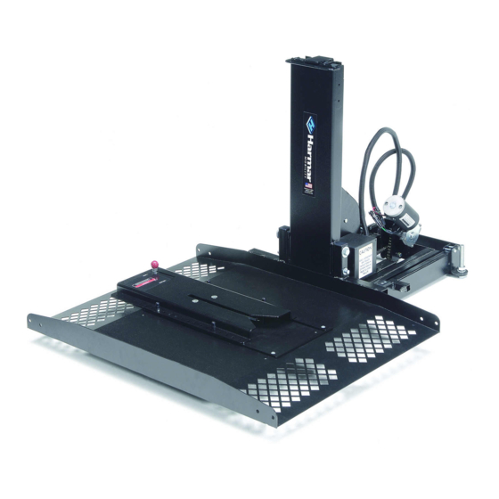
- Page 1 09-16-09 AL690 Side-Door Hybrid Lift AL600 Universal Hybrid Lift AL650 Hybrid Powerchair Lift w/ Docking Station...
-
Page 2: Unpacking The Lift
Be sure to check the contents of the box agaisnt the package checklist assuring that all parts are present. If any parts are missing, or damage is noted, contact your dealer immediately. DO NOT attempt to install or operate a lift with missing or damaged parts. AL600 AL650 VEHICLE HARNESS... -
Page 3: Important Note
WIRING THE VEHICLE IMPORTANT NOTE: IMPROPER WIRING IS THE #1 CAUSE OF PROBLEMS IN THE OPERATION OF A VEHICLE LIFT. FOLLOW THE WIRING INSTRUCTIONS CAREFULLY LOCATED IN THE HARDWARE P ACK IS THE VEHICLE WIRING HARNESS. THE HARNESS IS MANUFACTURED TO, AND COMPLIES WITH, THE SAE J1128 REQUIREMENTS. - Page 4 CLEARANCE = 1.75 INCHES 1.75" - 2" 2.25" GROUND 2.5" 2.75" 3" 3.25" 3.5" 3.75" 4" 4.25" AL650 AL650 HARDWARE USED: THEN USE: ( from hardware pack ) No Spacers MOUNTED ON LIFT FROM FACTORY .25" spacers 0.25" 0.25" 0.25" 0.25"...
- Page 5 AL650 AL 650 - SETTING DOCK STATION HEIGHT ONLY REMOVE LOCKING STATION AND INSERT APPROPRIATE NUMBER OF SPACERS. RE-ATT ACH TO PLATFORM. CHANGE TO LONGER SCREWS IF NECESSARY. ADD SPACERS AS REQUIRED ACCORDING TO CHAIR’S GROUND CLEARANCE ( CHART ON PREVIOUS PAGE )
- Page 6 AS TEMPLATE. DRILL AS REQUIRED. ATTACH TO CHAIR USING SUPPLIED HARDWARE: 4 - 1/4-20 x 1.00” HHCS 4 - 1/4-20 NYLOC NUT ( ATTACHED TO PLATE ) AL650 CHOOSING A LOCATION and MOUNTING THE DOCKING DEVICE PLATE ( CENTER )
- Page 7 AL600 & AL690 CHAIR / SCOOTER PREPARATION THERE ARE 2 OPTIONS ON HOW TO ATTACH THE STRAP HOOKS TO THE CHAIR THAT ARE INCLUDED WITH THE LIFT. ANCHOR PLATE: THE ANCHOR PLATE IS A FLAT PLATE THAT IS 20” LONG WITH A SLOT IN EACH END. THIS PLATE WILL WORK WITH ANY CHAIR OR SCOOTER THAT HAS A CENTER SEAT POST AND ATTACHES TO THE BOTTOM OF THE SEAT.
- Page 8 REMOVE 3rd ROW SEAT PLACE LEG ASSEMBLY LOAD LINE (CLOSED DOOR INNER SURFACE) 32” 42” LOCATE LEG CENTER 32” to 42” FROM LOAD LINE WHERE SEAT ATTACHMENT POINTS MAY LIE 2nd ROW SEATING IF NO POINTS ARE AVAILABLE DRILL IN THIS AREA, 15-1/2”...
- Page 9 AL 690 - INSTALLATION AL600 & AL650 REMOVE 2nd ROW SEAT PLACE LEG ASSEMBLIES (PASSENGER SIDE EXIT SHOWN) LOAD LINE (CLOSED DOOR INNER SURFACE) 3rd ROW SEATING LOCATE REAR LEG 42”to 52” CENTER IN FROM LOAD LINE DOOR WAY WHERE SEAT...
- Page 10 Loading a Power Chair Parking the Chair on the Platform: Before loading the power chair, verify that the platform has been lowered all the way to the ground. Set your chair’s speed control at a slow speed so that you may maneuver comfortably onto the platform.
- Page 11 AL600 AL 600 - LOADING A SCOOTER Parking the Scooter on the Platform: Before loading the scooter, verify that the platform has been lowered all the way to the ground. Set your scooter’s speed control at a slow speed so that you may maneuver comfortably onto the platform.
- Page 12 Parking the Chair on the Platform: Before loading the power chair, verify that the platform has been lowered all the way to the ground. Set your chair’s speed control at a slow speed so that you may maneuver comfortably onto the platform. Drive the chair onto the platform into the opening of the docking station.
- Page 13 AL 690 - LOADING A POWER CHAIR or MICRO SCOOTER Parking the Chair on the Platform: Before loading the power chair, verify that the platform has been lowered all the way to th e ground. Set your chair’s speed control at a slow speed so that you may maneuver comfortably onto the platform.
-
Page 14: Maintenance
SAFETY: Caution: Do not operate this lift until your dealer has satisfactorily instructed you in the proper operation of the lift. Your Harmar lift has been engineered and designed for years of trouble free use. Although, with everyday use, some parts may become loose or worn. IMPORTANT! Check regularly for any worn, loose or damaged parts of your lift. - Page 15 NOTES LIFT MODEL NUMBER: ___________________________________ SERIAL NUMBER : _______________________________________ SERVICE PERFORMED : ______________________________________________________________________ SERVICE PERFORMED : ______________________________________________________________________ SERVICE PERFORMED : ______________________________________________________________________ SERVICE PERFORMED : ______________________________________________________________________ SERVICE PERFORMED : ______________________________________________________________________ GENERAL NOTES: DATE: __________________ DATE: __________________ DATE: __________________ DATE: __________________ DATE: __________________...
-
Page 16: Exploded Views
ASSEMBLY PARTS DESCRIPTION ITEM QT Y PART NO. 90126A029 0.25 MW: 0.625 OD NL: 0.25-20 90640A129 92949A552 BSCS: 0.25-20 x 2.50 H600141 AL600 BASEWHEEL BASE WHEEL SPACER TUBE H600151 H600803 HPL BASE & LEG DETAIL A (x6) ITEM EXPLODED VIEWS SEE DETAIL A ASSEMBLY PARTS PART NO. - Page 17 EXPLODED VIEWS ASSEMBLY PARTS ITEM QT Y PART NO. 2BASSE-ASSY AL600 ASSEMBLY PART 2 91266A250 SHCS: 10-32 X 0.375 92949A566 BSCS: 0.25-28 x 1.00 98306A280 CLEVIS PIN, 3/8" x 2-3/8 L ALA21410 FLANGE BUSHING BRZ 3/8X1/2X3/8 ALA41011_CC L H600802 HORIZONTAL CHAIN ALA60020_QTY_ 2 ALA60022 H600802 VERTICAL CHAIN...
- Page 18 EXPLODED VIEWS ASSEMBLY PARTS ITE M PART NO. DESCRIPTION 4ASS Y AL600 ASSY ( in progress ) 93310A242 BSCS: 10-24 x 0.50 ALA60061 ROLLE R H600131 AL600 COVER TOP H600200 AL600 DRIVERSIDE WHEELS ASSEMBLY PARTS ITE M QT Y PART NO. DESCRIPTION 5ASSY AL600 ASSEMBLY PART 5...
- Page 19 EXPLODED VIEWS ASSEMBLY PARTS ITE M QT Y PART NO. 0_25-20_LOCK_NU T 6ASSY 90298A534 90298A535 90298A539 90471A413 FlPhHd, 100 degree, 1/4-20 x 3/4"L zp STEEL 92196A313 92865A538 HHCS, 1/4-20 x 5/8"L, GRADE ZP STEEL 92949A113 9654K614 ALA50006 ITE M QT Y DESCRIPTION 90640A129 AL600 ASSEMBLY PART 6...
-
Page 20: Docking Station
AL-600 / ITE M AL-690 EXPLODED VIEWS A L 6 A L 6 ASSEMBLY PARTS QT Y PART NO. DESCRIPTION BASE LEG BRACKET H600144 HHCS 1/2-13 x 4.00”L GRADE 5 ZP STEEL J-HOOK ZINC PLATED - 3/8” DIA ALA60133 BASE WASHER H600160 HEX JAM NUT, 1/2-13 NUT, 3/8-16...
Need help?
Do you have a question about the AL650 and is the answer not in the manual?
Questions and answers