Table of Contents
Advertisement
SeT uP and OPeraTing inSTrucTiOnS
Visit our website at: http://www.harborfreight.com
read this material before using this product.
Failure to do so can result in serious injury.
SaVe ThiS Manual.
©
Copyright
1998 by Harbor Freight Tools
contained herein may be reproduced in any shape or form without the express written consent of
Harbor Freight Tools. Diagrams within this manual may not be drawn proportionally. Due to continuing
improvements, actual product may differ slightly from the product described herein. Tools required for
assembly and service may not be included.
For technical questions or replacement parts, please call 1-800-444-3353.
Manual revised 10e
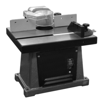
1/2" Bench TOP
ShaPer/rOuTer
Model
®
. All rights reserved. No portion of this manual or any artwork
32650
Advertisement
Table of Contents

Related Manuals for Central Machinery 32650


Summary of Contents for Central Machinery 32650
- Page 1 Harbor Freight Tools. Diagrams within this manual may not be drawn proportionally. Due to continuing improvements, actual product may differ slightly from the product described herein. Tools required for assembly and service may not be included.
-
Page 2: Table Of Contents
ShaPing and rOuTing TechniqueS ... 18 MainTenance and SerVicing ...20 cleaning, MainTenance, and luBricaTiOn ... 20 carBOn BruSh rePlaceMenT ... 21 TrOuBleShOOTing ... 22 ParTS liST ...24 aSSeMBlY diagraM ...25 liMiTed 1 Year / 90 daY WarranTY ...26 reV 10e SKU 32650... -
Page 3: Important Safety Information
10e SKU 32650 For technical questions, please call 1-800-444-3353. nOTice is used to address practices not related to personal injury. cauTiOn, without the... -
Page 4: Extension Cord
DIRECTION OF FEED. Feed work into a blade or cutter against the direction of rotation of the blade or cutter only. NEVER LEAVE TOOL RUNNING UNATTENDED. TURN POWER OFF. Don’t leave tool until it comes to a complete stop. reV 10e SKU 32650... -
Page 5: Grounding Instructions
Use only 3-wire extension cords that have 3-prong grounding plugs and reV 10e SKU 32650 For technical questions, please call 1-800-444-3353. 3-pole receptacles that accept the tool’s plug. Repair or replace damaged or worn cord immediately. - Page 6 Maintain labels and nameplates on the tool. These carry important safety information. If unreadable or missing, contact Harbor Freight Tools for a replacement. Avoid unintentional starting. Prepare to begin work before turning on the tool. People with pacemakers should consult their physician(s) before use.
- Page 7 Let the tool do the work. To reduce vibration, maintain the tool as explained in this manual. If any abnormal vibration occurs, stop use immediately. SaVe TheSe inSTrucTiOnS. reV 10e SKU 32650 For technical questions, please call 1-800-444-3353. Page 7...
-
Page 8: Specifications
Carbon Brushes Spindle Wrench (54) (3b) Double Ended Wrench (55) Shaper Collar (53) Spindle Washer (13) (47) Keyed Washer (48) Figure 1 Miter Gauge Assembly Switch (27a) Base (25) Table Insert (8) Belt (34) Nut (49) reV 10e SKU 32650... -
Page 9: Instructions For Putting Into Use
(4) holding the Half and Long Fence (2a and 2b) pieces from the Table Top (7). Discard the foam sheet. reV 10e SKU 32650 For technical questions, please call 1-800-444-3353. Mount the Shaper/Router to a permanent location such as a work bench, or to a portable plywood base. -
Page 10: Operating Instructions
TO PreVenT SeriOuS injurY: dO nOT OPeraTe WiTh anY guard diSaBled, daMaged, Or reMOVed. Lower Raise Main Main Spindle Spindle Height Knob (16) SKU 32650 reV 10e... -
Page 11: Removing Or Installing The Shaper Spindle
The Shaper/Router is packaged with the Shaper Spindle (47) installed so that the unit is ready for use as a shaper. To use the unit as a router, the Shaper Spindle must be removed. Reinstall the Shaper Spindle when using shaper cutters. -
Page 12: Table Insert
The Table Insert (8) is used to reduce wood chips falling into the machine which could cause flying debris. With router bit use, it also covers any unused portion of the bit below the surface of the Table Top (7). -
Page 13: Installing Router Bits
Nut (49) and the Height Knob (16) securely. installing router Bits Remove the Shaper Spindle (47) if it is installed. reV 10e SKU 32650 For technical questions, please call 1-800-444-3353. Router Collet Nut (51) Double Ended Wrench Router Bit... -
Page 14: Guard And Guide Locations
Place the Half Fence (2a) on the Long Fence as shown above. Adjust the Fence as needed for the project, then secure in place with the Knob (4). Fence Long Fence (2b) Knobs (4) Half Fence (2a) Table Top (7) SKU 32650 reV 10e... -
Page 15: Ring Guard
To assemble the Ring Guard, slide the Post (12) into the slot on the Ring Guard and secure in place with the Bolt (10). reV 10e SKU 32650 For technical questions, please call 1-800-444-3353. Ring Guard (11) Figure 19 To install the Ring Guard, slide the Post into the hole in the Table Top (7). -
Page 16: Radius Pin
Radius Pin (6) Ring Guard (11) Radius Pin (6) Table Top (7) Miter gauge Miter Bar (1c) Miter Knob (1d) Slots to secure workpiece Miter Indicator (1b) SKU 32650 reV 10e... -
Page 17: Switch And Key
The Switch Key (27b) can be removed when the switch is in the off position only. Make sure the machine is unplugged before removing the Switch Key. reV 10e SKU 32650 For technical questions, please call 1-800-444-3353. Miter Gauge Assembly (1) Switch Key (27b) in... -
Page 18: General Operating Instructions
Splintering of the back edge will occur when attempting cross-grain cuts. There are two ways to reduce this problem: Cut the workpiece 1/4” oversize (lengthwise) and trim off excess. Clamp a piece of scrap to trailing end. reV 10e SKU 32650... - Page 19 Try out the setting on a piece of scrap. Shut off and unplug router when about 2” of test piece is adjacent to the outfeed side of fence. Clamp scrap. Loosen the three knobs holding the fence and segment.
-
Page 20: Maintenance And Servicing
(39) and slide the Plate off of the unit. inspect the Figure 27 Unthread the Screw (31) holding the Belt Guard (33) in place and remove the Belt Guard. Remove Loosen Screws Screws (22) (22) Screw (31) Belt Guard (33) SKU 32650 reV 10e... -
Page 21: Carbon Brush Replacement
Brush replacement Replacement Carbon Brushes (3b) are included with this unit. The Carbon Brushes should be replaced by a qualified technician. reV 10e SKU 32650 For technical questions, please call 1-800-444-3353. Bolts (35) Belt (34) Page 21... -
Page 22: Troubleshooting
Eliminate use of extension cord. If an extension cord is needed, use one with the proper diameter for its length and load. See Extension Cords in GROUNDING section. likely Solutions SKU 32650... -
Page 23: Please Read The Following Carefully
If product has no serial number, record month and year of purchase instead. note: Some parts are listed and shown for illustration purposes only, and are not available individually as replacement parts. reV 10e SKU 32650 For technical questions, please call 1-800-444-3353. Page 23... -
Page 24: Parts List
#1/2”-20 Nut M12 x 1.25 EFT Router Bit Collet Router Collet Nut #3/4 - 10 2-1/2 Male to 1-1/4 Female Adapter Collar Spindle Wrench Double Ended Wrench Nut (not shown) - Packing nut for Height Knob Stud description reV 10e SKU 32650... -
Page 25: Assembly Diagram
10e SKU 32650 For technical questions, please call 1-800-444-3353. aSSeMBlY diagraM Page 25... -
Page 26: Limited 1 Year / 90 Day Warranty
1 Year / 90 daY WarranTY Harbor Freight Tools Co. makes every effort to assure that its products meet high quality and durability standards, and warrants to the original purchaser that for a period of ninety days from date of purchase that the engine/motor, the belts (if so equipped), and the blades (if so equipped) are free of defects in materials and workmanship.
Need help?
Do you have a question about the 32650 and is the answer not in the manual?
Questions and answers
Are parts and collets still available for the 32650 shaper router?
Some parts for the Central Machinery 32650 shaper router are listed for illustration purposes only and may not be available individually as replacement parts. Collets are mentioned in the manual, but it is unclear if they are available separately for purchase. For technical questions or parts inquiries, you can call 1-800-444-3353.
This answer is automatically generated