Table of Contents
Advertisement
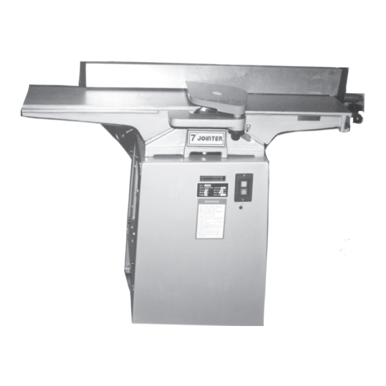
7" RABBETING
JOINTER WITH STAND
31849
Assembly & OPERATING INSTRUCTIONS
®
3491 Mission Oaks Blvd., Camarillo, CA 93011
Visit our Web Site at www.harborfreight.com
®
Copyright © 2000 by Harbor Freight Tools
. All rights reserved. No portion of this manual
or any artwork contained herein may be reproduced in any shape or form without the ex-
press written consent of Harbor Freight Tools.
For technical questions and replacement parts please call 1-800-444-3353.
Advertisement
Table of Contents

Related Manuals for Central Machinery 31849


Summary of Contents for Central Machinery 31849
- Page 1 3491 Mission Oaks Blvd., Camarillo, CA 93011 Visit our Web Site at www.harborfreight.com ® Copyright © 2000 by Harbor Freight Tools . All rights reserved. No portion of this manual or any artwork contained herein may be reproduced in any shape or form without the ex- press written consent of Harbor Freight Tools.
- Page 2 THANK YOU for choosing a HARBOR FREIGHT TOOLS product. For future reference, please complete the owner’s record below: Model______________ Serial No.______________ SAVE THE RECEIPT, WARRANTY AND THESE INSTRUCTIONS. It is important that you read the entire manual to become familiar with the unit BEFORE you begin assembly.
- Page 3 Maintenance: For your own safety, maintenance should be performed regularly by a qualified technician. Caution: Some woods contain preservatives such as copper chromium arsenate (CCA) which can be toxic. When cutting these materials extra care should be taken to avoid inhalation and minimize skin cintact. #31849 Page 3...
-
Page 4: Extension Cords
AWG rating. Every cord must meet the AWG rating. Use the chart below to determine what AWG rating is required for your situation. Cord length is rated in feet. Harbor Freight Tools can supply UL listed and outdoor rated cords in multiple AWG ratings if needed. - Page 5 Attach a Lock Plate (part #24A) to each corner hole and to the top hole in the Left Protecting Plate (#26A). Make certain that the part of the Lock Plate with the wing is on the outside of the Protecting Plate-see Figure 2. #31849 Roof (1A) Rear Side Plate (30A)
- Page 6 Loosen the Nuts and Bolts on the Upright Plate (#4A-Stand Assembly). Move the Motor up or down along the Upright Plate until the correct tension is achieved. Tighten Nuts and Bolts into place-see Figure 3. #31849 Left Tapping Fender (#27) Tapping Plate (#25A)
- Page 7 Attach the Handle Pole (#29) and Socket (#30) over the Nut. Attach Cap (#31) and tighten into place-see Figures 5, 6 and 7. Bolt (27) Washer (25) Socket (30) Figure 5 #31849 Figure 3 Nut (26) Handle Pole (29) Figure 4...
- Page 8 For both the Infeed Table (#33) and Out Feed Table (#1) loosen the Lock Screw (#45) nearest the Handle Wheel (#43). Turn the Handle Wheel until the Table is set at the proper height. Once the table is set as desired, tighten down the Lock Screw (#56). #31849 Plate Operation...
- Page 9 Step 3) Place a steel straight edge on the outfeed table so that it also covers the cutterhead. Carefully turn the cutterhead so that the knives are barely touching the straight edge. #31849 Figure 8 - Grain Direction Page 9...
- Page 10 Carefully turn the cutterhead, until its round side is showing on top. Place a .060" feeler gauge on the cutterhead. With a straight edge on the rear table adjust the height of the rear table to .060". #31849 REV 02/05 Page 10...
- Page 11 Jointer and is tightened into place by sliding on a Lock Washer and then a Nut. Do not tighten into place until both green wires are attached to the ground-see Figure 10 and 12. Green Wires Ground Figure 10 #31849 Outlet Switch Box White from Outlet White from Motor...
- Page 12 AND NOT BY THE BUYER. THE BUYER ASSUMES ALL RISK AND LIABILITY ARISING OUT OF HIS OR HER REPAIRS TO THE ORIGINAL PRODUCT OR REPLACEMENT PARTS THERETO, OR ARISING OUT OF HIS OR HER INSTALLATION OF REPLACEMENT PARTS THERETO. #31849 Black to corners White to corners...
- Page 13 When unpacking your Jointer with Stand check to make sure the following parts are included. If any parts are missing or broken, please call HARBOR FREIGHT TOOLS at 1-800-444-3353. Parts List - Stand Assembly Part # Description Roof Upper Link Plate...
- Page 14 Fence Segment Tilt Angle Seat Hex Screw Washer Bolt Handle Ball Handle Pole Socket Cutter Guard Infeed Table Retainer Washer Depth Scale #31849 Quantity Part # Description Spring Spring Knob Retainer Recessed Screw Belt Washer Handle Wheel Lock Washer Lock Screw...
- Page 15 Stand Assembly Diagram Each of the Part Numbers below correspond to the Stand Assembly and has the suffix “A” - see Parts List on Page 13. #31849 Page 15...
- Page 16 Jointer Assembly Diagram - See Parts List on Page 14 #31849 Page 16...
- Page 17 Wiring Diagram Black White Black White #31849 Page 17...
Need help?
Do you have a question about the 31849 and is the answer not in the manual?
Questions and answers