Advertisement
Table of Contents
Owner's Manual & Safety Instructions
Save This Manual
operating, inspection, maintenance and cleaning procedures. Write the product's serial number in the
back of the manual near the assembly diagram (or month and year of purchase if product has no number).
Keep this manual and the receipt in a safe and dry place for future reference.
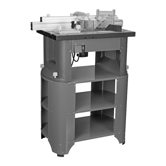
1 HP ROUTER
When unpacking, make sure that the product is intact
and undamaged. If any parts are missing or broken,
please call 1-888-866-5797 as soon as possible.
©
Copyright
2004 by Harbor Freight Tools
No portion of this manual or any artwork contained herein may be reproduced in
any shape or form without the express written consent of Harbor Freight Tools.
Diagrams within this manual may not be drawn proportionally. Due to continuing
improvements, actual product may differ slightly from the product described herein.
Tools required for assembly and service may not be included.
Keep this manual for the safety warnings and precautions, assembly,
Visit our website at: http://www.harborfreight.com
Email our technical support at: productsupport@harborfreight.com
®
. All rights reserved.
TABLE
WITH
Read this material before using this product.
Failure to do so can result in serious injury.
SAVE THIS MANUAL.
REV 15l
ITEM 91130
Advertisement
Table of Contents

Related Manuals for Central Machinery 91130


Summary of Contents for Central Machinery 91130
- Page 1 1 HP ROUTER TABLE WITH Visit our website at: http://www.harborfreight.com ITEM 91130 Email our technical support at: productsupport@harborfreight.com When unpacking, make sure that the product is intact and undamaged. If any parts are missing or broken, please call 1-888-866-5797 as soon as possible.
-
Page 2: Table Of Contents
4. DON’T USE IN DANGEROUS ENVIRONMENT. to do a job for which it was not designed. Don’t use power tools in damp or wet locations, or expose them to rain. Keep work area well lighted. Page 2 For technical questions, please call 1-888-866-5797. Item 91130... - Page 3 It’s safer than using your hand and it frees both hands to operate tool. 21. NEVER LEAVE TOOL RUNNING UNATTENDED. TURN POWER OFF. Don’t leave tool until it comes to a complete stop. Item 91130 For technical questions, please call 1-888-866-5797. Page 3...
-
Page 4: Router Safety Warnings
3. Feed workpiece against rotation of cutter. 7. Construct an appropriate Push Stick out of wood according to the guidelines on the following page. Page 4 For technical questions, please call 1-888-866-5797. Item 91130... -
Page 5: Features And Functions
30°-40° of the stick to keep hands out of the line of the blade. • The lower lip of the notch must be no longer than the workpiece is thick. Item 91130 For technical questions, please call 1-888-866-5797. Page 5... -
Page 6: Vibration Safety
If you feel any medical or physical symptoms related to vibration (such as tingling, numbness, and white or blue fingers), seek medical advice as soon as possible. SAVE THESE INSTRUcTIONS. Page 6 For technical questions, please call 1-888-866-5797. Item 91130... -
Page 7: Specifications
4. If mounting Support Stand to floor, bolt down using Bracket Foot four Floor Mounting Brackets. Secure in place using Support bolts (not included) through holes on Brackets. Figure B Item 91130 For technical questions, please call 1-888-866-5797. Page 7... - Page 8 4. Secure the Table Stand to the Support Stand using four Washers (21) and Lock Knobs (22) threaded onto the Square Head Support Stand Bolts from the top. Refer to Figure E. Figure E Page 8 For technical questions, please call 1-888-866-5797. Item 91130...
- Page 9 4. Hold Power Switch Assembly against the inside of the Front Plate. Secure in place using M6 x 1 6 Bolts (23) and M6 Nuts (31). Alignment Alignment Hole Hole Bolt Table Top Figure H Item 91130 For technical questions, please call 1-888-866-5797. Page 9...
- Page 10 Top Fence. 3. Secure Dust Port assembly in place on the Top Fence using two M6 x 1 6 Bolts (49). Dust port Lock Assembly Knob Figure K Page 10 For technical questions, please call 1-888-866-5797. Item 91130...
- Page 11 Fence Adjusting Knob Fence Lock Support Knob Dust port Bottom Fence Fence channel Height Adjustment collet Nut Arrow Height Adjusting Spindle Ring Lock collet Assembly Motor cover Height Adjustment Lock Item 91130 For technical questions, please call 1-888-866-5797. Page 11...
-
Page 12: Operation
Assembly Cover (81) and lift Cover from Height Adjusting Ring (80). If necessary, clean off collet Nut any debris from previous cutting operations. collet Assembly cover collet Height Adjusting Figure O Ring Figure M Page 12 For technical questions, please call 1-888-866-5797. Item 91130... - Page 13 5. Once depth of cut is determined, align the Height Adjustment Lock and turn clockwise to lock. Note: Always make a trial cut on scrap wood to ensure the correct depth of cut. Figure R Item 91130 For technical questions, please call 1-888-866-5797. Page 13...
- Page 14 3. To adjust the Bottom Fence(s), loosen the appropriate Fence Adjusting Knobs. Bottom Fences Lock Lock 4. Slide the Bottom Fence(s) in or out to the desired Knob Knob position. Retighten Fence Adjusting Knobs. Page 14 For technical questions, please call 1-888-866-5797. Item 91130...
-
Page 15: General Operating Instructions
Note: Using the correct speed increases the life of the router bit and improves the surface finish of the workpiece. Determine optimum speed by making a trial cut on scrap wood. power Switch cover Item 91130 For technical questions, please call 1-888-866-5797. Page 15... -
Page 16: Maintenance
WARNING! If the supply cord of this 2. AFTER USE, wipe external surfaces power tool is damaged, it must be replaced of the tool with clean cloth. only by a qualified service technician. Page 16 For technical questions, please call 1-888-866-5797. Item 91130... -
Page 17: Troubleshooting
Note: If product has no serial number, record month and year of purchase instead. Note: Some parts are listed and shown for illustration purposes only, and are not available individually as replacement parts. Item 91130 For technical questions, please call 1-888-866-5797. Page 17... -
Page 18: Parts List And Diagram
THERETO, OR ARISING OUT OF HIS OR HER INSTALLATION OF REPLACEMENT PARTS THERETO. Support Stand parts List part Description part Description Foot Support Leg Foot Support Tray Washer M5 Bolt M5 x 1 2 Lock Nut M5 Floor Mounting Bracket Page 18 For technical questions, please call 1-888-866-5797. Item 91130... - Page 19 Support Stand Assembly Diagram Item 91130 For technical questions, please call 1-888-866-5797. Page 19...
-
Page 20: Table Parts List
Screw 3.5 x 1 3 Washer Terminal Lock Knob Press Board Bolt M6 x 1 6 Terminal Block Washer M6 Square Head Bolt M6 x 3 0 Page 20 For technical questions, please call 1-888-866-5797. Item 91130... - Page 21 Table Assembly Diagram Item 91130 For technical questions, please call 1-888-866-5797. Page 21...
-
Page 22: Fence Parts List
Square Head Bolt M6 x 3 0 Fence Support Guard Hex Nut M6 Guard Base Right Top Fence Cover Screw 2.9 x 9 Fence Adjusting Knob Dust Port Page 22 For technical questions, please call 1-888-866-5797. Item 91130... - Page 23 Fence Assembly Diagram Item 91130 For technical questions, please call 1-888-866-5797. Page 23...
- Page 24 Small Spring Slip Groove Height Adjustment Lock Collet 1/4" Turning Piece Steel Bead Small Washer B Small Washer C Locking Piece Partiality Axle Adjustment Tool Large Washer Height Adjusting Ring Page 24 For technical questions, please call 1-888-866-5797. Item 91130...
- Page 25 Adjustment Board Assembly Diagram Item 91130 For technical questions, please call 1-888-866-5797. Page 25...
- Page 26 Connector Spindle Lock Terminal Block Spring Washer Bolt M4 x 2 0 Earth Line Cover Bearing 6904R Screw M4 x 8 Dust Cover Tie Strip 80 m m Page 26 For technical questions, please call 1-888-866-5797. Item 91130...
- Page 27 Motor Assembly Diagram Item 91130 For technical questions, please call 1-888-866-5797. Page 27...
-
Page 28: Warranty
This warranty gives you specific legal rights and you may also have other rights which vary from state to state. 3491 Mission Oaks Blvd. • pO Box 6009 • camarillo, cA 93011 • 1-888-866-5797 Page 28 For technical questions, please call 1-888-866-5797. Item 91130...
Need help?
Do you have a question about the 91130 and is the answer not in the manual?
Questions and answers
LOOKING FOR PART 115 DIAGRAM E