Table of Contents
Advertisement
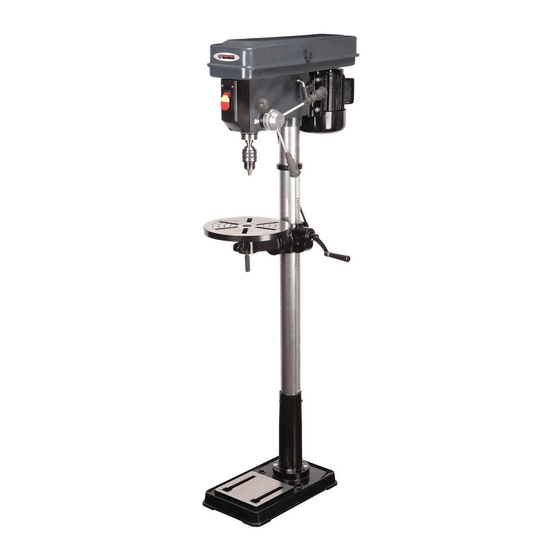
38144
16-Speed Drill Press
Assembly and Operating Instructions
®
3491 Mission Oaks Blvd., Camarillo, CA 93011
Visit our Web site at http//www.harborfreight.com
®
Copyright
1998 by Harbor Freight Tools
. All rights reserved. No portion of this
manual or any artwork contained herein may be reproduced in any shape or form
without the express written consent of Harbor Freight Tools.
For technical questions, please call 1-800-444-3353.
Advertisement
Table of Contents

Related Manuals for Central Machinery 38144


Summary of Contents for Central Machinery 38144
- Page 1 1998 by Harbor Freight Tools . All rights reserved. No portion of this manual or any artwork contained herein may be reproduced in any shape or form without the express written consent of Harbor Freight Tools. For technical questions, please call 1-800-444-3353.
-
Page 2: Technical Specifications
Remove all preservative lubricants from parts with a clean dry cloth. Some of the parts are heavy and may require two people for lifting. If any parts are missing or broken, please call Harbor Freight Tools at 1-800-444-3353. The shipping box should contain: Table Assembly... - Page 3 Figure 2 #38144 REV 10/03 Figure 1 Spindle Belt is M24 Motor Belt is M25 Page 3...
-
Page 4: Work Area
Keep proper footing and balance at all times. Do not reach over or across running machines. Always check that adjusting keys and wrenches are removed from the tool or machine work surface before plugging it in. #38144 WORK AREA FIRE AND SHOCK... -
Page 5: Before Operating
Do not use the tool if any switch does not turn off and on properly. Operation This drill press is designed for use with DRILL BITS and MORTISING ATTACHMENTS only. The use of other cutting tools or accessories could be hazardous. -
Page 6: Head To Column
MOUNTING SURFACE: Ideally, the base should be firmly bolted to the floor or workbench prior to assembly of other compo- nents. The mounting surface must be flat, level and capable of supporting the drill press’weight combined with materials to be drilled. -
Page 7: Installing The Chuck
1/2” at their centers of run when using reasonable thumb pressure. Lock the motor in this position using the locking screw. Note: If the belt slips during operation, adjust the belt tension. Settings and Adjustments #38144 (Please refer to Figure 3) Figure 3... -
Page 8: To Adjust The Table
0 degrees. To ensure the drill is entirely perpendicular to the table, insert a piece of straight round bar in the chuck, place a square on the table and bring it up to the round bar. Adjust the table tilt if necessary so that the table is correctly aligned. -
Page 9: Operation
The scrap piece of wood must make contact with the left side of the column as shown in Figure 6. Also, set the depth of the drill so that the drill will not come in contact with the table - or align the table so that the hole in its center is in line with the drill bit. -
Page 10: Drill Speed Table
Drill Speed Table Note: Spindle Belt M24, Motor Belt M25 The table below shows the belt arrangements for given drill speeds (a full chart is also located on the inside of the pulley cover). After Operation Remove all residue from the machine and thoroughly clean all surfaces. -
Page 11: Extension Cords
REPLACEMENT PARTS: Replace belts at the first sign of slippage or fraying. When servicing, use only identical replacement parts. Use of any other parts will void the warranty. STORAGE: Always remove and store drill bits. KEEP OUT OF REACH OF CHILDREN... - Page 12 #38144 Page 12...
- Page 13 Spindle Pulley Pulley Insert Ball Bearing17mm 60203 GB2778-89C Spacer Retaining Ring 17mm Retaining Ring 11mm Ball Bearing 60201 Quill Gasket Quill Ball Bearing 80202 Spindle Shaft Arbor #38144 Item 1505010 1302025 1305009A 1302022 1302023 GB894.1-86B GB894.1-86A GB278-89A 1303003 1303002B GB278-89D...
- Page 14 Hex. Nut M8 Washer M8 Motor Cable Hex. Screw M8 Belt Tension Lock Knob 1502005 Belt Tension Lever Roll Pin Head Lock Set Screw M8 GB80-85B Depth Lock Screw Knob #38144 Item 15020114A GB818-85B GB5781-86B 1502006 1502002 1502003 1502007A GB93-87...
- Page 15 Figure 9 - Parts List - Base and Table Part Numbers shown here have a “B” suffix #38144 Item Description Column Rack Hex. Socket Screw Set M10 Column Support Hex. Head Screw Base Table Support w/indicator Crank Gear Pin Skt. Screw Set M6...
Need help?
Do you have a question about the 38144 and is the answer not in the manual?
Questions and answers