Table of Contents
Advertisement
Quick Links
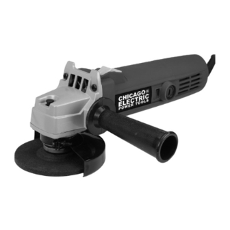
4" ANGLE GRINDER
91222
ASSEMBLY & OPERATING INSTRUCTIONS
3491 Mission Oaks Blvd., Camarillo, CA 93011
Visit our Web site at http://www.harborfreight.com
©
®
Copyright
2004 by Harbor Freight Tools
. All rights reserved. No portion
of this manual or any artwork contained herein may be reproduced in any shape or
form without the express written consent of Harbor Freight Tools.
For technical questions and replacement parts, please call 1-800-444-3353
Advertisement
Table of Contents

Summary of Contents for Chicago Electric 91222
- Page 1 . All rights reserved. No portion of this manual or any artwork contained herein may be reproduced in any shape or form without the express written consent of Harbor Freight Tools. For technical questions and replacement parts, please call 1-800-444-3353...
-
Page 2: General Safety Rules
THANK YOU for choosing a HARBOR FREIGHT TOOLS product. For future reference, please complete the owner’s record below: Model_____________ SAVE THE RECEIPT, WARRANTY AND THESE INSTRUCTIONS. It is important that you read the entire manual to become familiar with the unit BEFORE you begin assembly. -
Page 3: Personal Safety
Disconnect the Power Cord Plug from the power source before making any adjustments, changing accessories, or storing the tool. Such preventive safety measures reduce the risk of starting the tool accidentally. SKU 91222 PERSONAL SAFETY TOOL USE AND CARE Page 3... -
Page 4: Specific Safety Rules
“live” and shock the operator. Maintain labels and nameplates on the Grinder. These carry important information. If unreadable or missing, contact Harbor Freight Tools for a replacement. Always wear safety impact eye goggles and heavy work gloves when using this tool. - Page 5 It must be understood by the operator that COMMON SENSE AND CAUTION ARE FACTORS WHICH CANNOT BE BUILT INTO THIS PRODUCT, BUT MUST BE SUPPLIED BY THE OPERATOR. SKU 91222 ” center mounting REV 02/07 Page 5...
-
Page 6: Grounded Tools: Tools With Three Prong Plugs
Underwriters Laboratories, Inc., the Canadian Standard Association, and the National Electrical Code. (See Figure B, above right.) Double insulated tools may be used in either of the 120 volt outlets shown in the upper right illustration. (See Figure B, above right.) SKU 91222 GROUNDING WARNING! FIGURE B... -
Page 7: Extension Cords
Protect your extension cords from sharp objects, excessive heat, and damp or wet areas. REQUIRED MINIMUM EXTENSION CORD GAUGE - 110 VOLT NAMEPLATE AMPERES (At Full Load) SKU 91222 EXTENSION CORDS EXTENSION CORD LENGTH 0-25 FT. 25-50 FT. FIGURE C 50-100 FT. - Page 8 When unpacking, check to make sure the following parts are included. All sizes listed below are approximate. If any parts are missing or broken, please call Harbor Freight Tools at the number on the cover of this manual. Refer to parts diagram at end of manual.
- Page 9 Handle The grinder comes with a SIDE HANDLE (#29) which can be screwed into either side of the grinder. (refer to Figure 1.) Installing Wheels Warning: Always disconnect from power source before adding or removing accessories. Use a cloth or glove to protect hands from abrasion.
- Page 10 (#2) Step 2: Using the WRENCH, loosen the WHEEL NUT by turning it counterclockwise. Step 3:Unscrew the WHEEL NUT and remove, then remove the GRINDING WHEEL from the SPINDLE SKU 91222 Figure 3 — Removing Wheels Wheel Nut (#1) Wrench...
-
Page 11: Starting The Grinder
Starting the Grinder Ensure the GRINDER is not locked ON before plugging it in. Check the SLIDE SWITCH (#19) and make sure it is in the OFF position before plugging it into the power source. Step 1: To turn the Grinder ON, push the Slide Switch (#19) forward with your thumb to the front position and the Grinder begins running. - Page 12 Figure 6 — Replacing the Carbon Brushes Step 2: Replace the CARBON BRUSH with identical replacement parts from Harbor Freight Tools. Step 3: Replace the BRUSH CAP on the HOUSING and screw-in to tighten. SKU 91222 MAINTENANCE WARNING: DO NOT DISASSEMBLE. CAUTION: clean, dry rag only.
- Page 13 AND NOT BY THE BUYER. THE BUYER ASSUMES ALL RISK AND LIABILITY ARISING OUT OF HIS OR HER REPAIRS TO THE ORIGINAL PRODUCT OR REPLACEMENT PARTS THERETO, OR ARISING OUT OF HIS OR HER INSTALLATION OF REPLACEMENT PARTS THERETO. SKU 91222 PARTS LIST Item #...
- Page 14 Assembly Diagram-Exploded View SKU 91222 Page 14...


Need help?
Do you have a question about the 91222 and is the answer not in the manual?
Questions and answers