Table of Contents
Advertisement
Quick Links
This publication, including photographs, illustrations and software,
is under the protection of international copyright laws, with all
rights reserved. Neither this manual, nor any of the material
contained herein, may be reproduced without the express written
consent of the manufacturer.
The information in this document is subject to change without
notice. The manufacturer makes no representations or warranties
with respect to the contents hereof and specifically disclaims any
implied warranties of merchantability or fitness for any particular
purpose. Further, the manufacturer reserves the right to revise this
publication and to make changes from time to time in the content
hereof without obligation of the manufacturer to notify any person
of such revision or changes.
Trademarks
IBM, VGA, and PS/2 are registered trademarks of International
Business Machines.
AMD, Duron and Athlon are registered trademarks of Advanced
Micro Devices Inc.
Microsoft, MS-DOS and Windows 98/ME/NT/2000/XP are
registered trademarks of Microsoft Corporation.
PC-cillin is a registered trademark of Trend Micro Inc.
AMI is a registered trademark of American Megatrends Inc.
Other names used in this publication may be trademarks and are
acknowledged.
Copyright © 2003
All Rights Reserved
MS8177C Series, V1.1
KT600/October 2003
Advertisement
Table of Contents

Subscribe to Our Youtube Channel
Related Manuals for MATSONIC MS8177C Series


Summary of Contents for MATSONIC MS8177C Series
- Page 1 PC-cillin is a registered trademark of Trend Micro Inc. AMI is a registered trademark of American Megatrends Inc. Other names used in this publication may be trademarks and are acknowledged. Copyright © 2003 All Rights Reserved MS8177C Series, V1.1 KT600/October 2003...
-
Page 2: Table Of Contents
Table of Contents Trademark ................I Static Electricity Precautions ..........III Pre-Installation Inspection..........III Chapter 1: Introduction............1 Key Features..............2 Package Contents ...............5 Chapter 2: Mainboard Installation..........6 Mainboard Components............7 I/O Ports................7 Installing the Processor............8 Installing Memory Modules ..........9 Jumper Settings ..............10 Install the Mainboard............ -
Page 3: Static Electricity Precautions
Static Electricity Precautions Static electricity could damage components on this mainboard. Take the following precautions while unpacking this mainboard and installing it in a system. 1. Don’t take this mainboard and components out of their original static-proof package until you are ready to install them. 2. - Page 4 Notice: 1. Owing to Microsoft’s certifying schedule is various to every supplier, we might have some drivers not certified yet by Microsoft. Therefore, it might happen under Windows XP that a dialogue box (shown as below) pop out warning you this software has not passed Windows Logo testing to verify its compatibility with Windows XP.
-
Page 5: Chapter 1: Introduction
Chapter 1 Introduction This mainboard has a Socket-A support for the AMD K7 processors. The Socket-A processor’s front-side bus speed is 400 MHz. This mainboard has the VIA KT600 Northbridge and VT8237 Southbridge chipsets that provide the support for Serial ATA devices, which is a new interface for high-performance and mainstream desktop PCs, at a bandwidth of 150MB/s per port. -
Page 6: Key Features
Key Features This mainboard has these key features: Socket-A Processor Support Supports AMD Athlon XP/Athlon/Duron processors Supports 400 MHz Front-Side Bus Chipset There are VIA KT600 Northbridge and VT8237 Southbridge in this chipset in accordance with an innovative and scalable architecture with proven reliability and performance. - Page 7 Expansion Options The mainboard comes with the following expansion options: Five 32-bit PCI slots One 8xAGP slot One CNR (Communications and Networking Riser) slot Onboard IDE Two IDE Connectors Supports PIO (Programmable Input/Output) and DMA (Direct Memory Access) modes Supports IDE Ultra DMA bus mastering with transfer rates of 133 /100/66/33 MB/sec Serial ATA Two Serial ATA Connectors...
- Page 8 Built-in Ethernet LAN (optional) 100Base-TX/10Base-T Physical Layer Solution Dual Speed – 100/10 Mbps MII Interface to Ethernet Controller/Configuration & Status Auto Negotiation: 10/100, Full/Half Duplex Meet All Applicable IEEE802.3, 10Base-T and 100Base- TX Standards USB 2.0 Compliant with Universal Serial Bus Specification Revision 2.0 Compliant with Intel’s Enhanced Host Controller Interface Specification Revision 0.95...
-
Page 9: Package Contents
Package Contents Your mainboard package contains the following items: The mainboard The User’s Manual One diskette drive ribbon cable (optional) One IDE drive ribbon cable The Software support CD Optional Accessories You can purchase the following optional accessories for this mainboard. -
Page 10: Chapter 2: Mainboard Installation
Chapter 2 Mainboard Installation To install this mainboard in a system, please follow these instructions in this chapter: Identify the mainboard components Install a CPU Install one or more system memory modules Make sure all jumpers and switches are set correctly Install this mainboard in a system chassis (case) Connect any extension brackets or cables to connectors on the mainboard... -
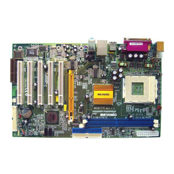
Page 11: Mainboard Components
Mainboard Components Identify major components on the mainboard via this diagram underneath. Note: Those jumpers of mainboard not appearing in this illustration are for testing only. I/O Ports The illustration below shows a side view of the built-in I/O ports on the mainboard. -
Page 12: Installing The Processor
Use the upper PS/2 port to connect a PS/2 PS/2 Mouse pointing device. Use the lower PS/2 port to connect a PS/2 PS/2 Keyboard keyboard. Use the Parallel port to connect printers or Parallel Port other parallel communications devices. (PRN) Use the COM port to connect serial devices COM1 such as mice or fax/modems. -
Page 13: Installing Memory Modules
1. Unhook the locking lever of the CPU socket. Pull the locking lever away from the socket and raising it to the upright position. 2. Match the pin1 corner marked as the beveled edge on the CPU with the pin1 corner on the socket. Insert the CPU into the socket. -
Page 14: Jumper Settings
Memory Module Installation Procedure These modules can be installed with up to 2 GB system memory. Following these steps to install the memory module. 1. Push down the latches on both sides of the DIMM socket. 2. Align the memory module with the socket. There is a notch on the DIMM socket that you can install the DIMM module in the correct direction. -
Page 15: Install The Mainboard
JP3: CPU Frequency Selector Use this jumper to select the CPU frequency. Frequency Pins 1-2 Pins 3-4 200 MHz 100 MHz 166 MHz 133 MHz Install the Mainboard Install the mainboard in a system chassis (case). The board is an ATX size mainboard. -
Page 16: Connecting Optional Devices
Connecting Optional Devices Refer to the following for information on connecting the mainboard’s optional devices: SIR1 USB3 AUDIO1 SPK1 USB2 SPK1: Speaker Connector Connect the cable from the PC speaker to the SPK1 connector on the mainboard. Pin Signal Pin Signal SPKR AUDIO1: Front Panel Audio Connector This connector allows the user to install auxiliary front-oriented... - Page 17 Signal Pin Signal VERG_FP_USBPWR0 2 VERG_FP_USBPWR0 USB_FP_P0 - USB_FP_P1 - USB_FP_P0+ USB_FP_P1+ GROUND GROUND USB_FP_OC0 1. Locate the USB2/3 connector on the mainboard. 2. Plug the bracket cable onto the USB2/3 connector. 3. Remove a slot cover from one of the expansion slots on the system chassis.
-
Page 18: Install Other Devices
Signal Pin Signal IRTX IRRX 1. Locate the infrared port SIR1 connector on the mainboard. 2. If you are adding an infrared port, connect the ribbon cable from the port to the IR1 connector and then secure the port to an appropriate place in your system chassis. - Page 19 Install the device(s) and connect power from the system power supply. Use the cable provided to connect the device(s) to the Primary IDE channel connector IDE1 on the mainboard. If you want to install more IDE devices, you can purchase a second IDE cable and connect one or two devices to the Secondary IDE channel connector IDE2 on the mainboard.
-
Page 20: Expansion Slots
Pin Signal CD IN L CD IN R Expansion Slots This mainboard has one AGP, one CNR and five 32-bit PCI slots. AGP1 CNR1 PCI5 PCI4 PCI3 PCI2 PCI1 Follow the steps below to install an AGP/CNR/PCI expansion card. 1. Locate the AGP, CNR or PCI slots on the mainboard. 2. -
Page 21: Chapter 3: Bios Setup Utility
Chapter 3 BIOS Setup Utility Introduction The BIOS Setup Utility records settings and information of your computer, such as date and time, the type of hardware installed, and various configuration settings. Your computer applies those information to initialize all the components when booting up and basic functions of coordination between system components. -
Page 22: Running The Setup Utility
Running the Setup Utility Every time you start your computer, a message appears on the screen before the operating system loading that prompts you to “Hit <DEL>if you want to run SETUP”. Whenever you see this message, press the Delete key, and the Main menu page of the Setup Utility appears on your monitor. -
Page 23: Standard Cmos Setup Page
Standard CMOS Setup Page This page helps you set up basic information such as the date and time, the IDE devices, and the diskette drives. AMIBIOS SETUP – STANDARD CMOS SETUP (C) 2000 American Megatrends, Inc. All Rights Reserved Date (mm/dd/yy) : Wed Oct 08, 2003 Time (hh/mm/ss) : 11:19:55 32Bit Type... -
Page 24: Advanced Setup Page
Advanced Setup Page This page sets up more advanced information about your system. Be more careful to this page. Any changes can affect the operation of your computer. AMIBIOS SETUP – ADVANCED SETUP (C) 2000 American Megatrends, In c. All Rights Reserved Quick Boot Enabled Boot Device... - Page 25 This item determines if the Num Lock BootUp Num- key is active or inactive at system start- Lock up time. If you have two diskette drives installed Floppy Drive and you enable this item, drive A Swap becomes drive B and drive B becomes drive A.
-
Page 26: Power Management Setup Page
Enable this item to increase SDRAM SDRAM Bank memory speed. When enabled, separate Interleave memory banks are set for odd and even addresses and the next byte of memory can be accessed while the current byte is being refreshed. When this item is enabled, BIOS will Auto detect disable the clock signal of free DIMM/PCI... - Page 27 Use this item to enable or disable a power Power management scheme. If you enable power Management management, you can use the items below to set the power management operation. Both APM and ACPI are supported. This sets the timeout for Suspend mode in Suspend Time minutes.
-
Page 28: Pci/Plug And Play Setup Page
PCI / Plug and Play Setup Page This page sets up some parameters for devices installed on the PCI bus and those utilizing the system plug and play capability. AMIBIOS SETUP – PCI / PLUG AND PLAY SETUP (C) 2000 American Megatrends, Inc. All Rights Reserved Primary Graphics Adapter Allocate IRQ to PCI VGA PCI IDE BusMaster... -
Page 29: Load Best Performance Settings
Load Best Performance Settings If you select this item and press Enter a dialog box appears. If you press Y, and then Enter, the Setup Utility loads a set of best- performance default values. These default values are quite demanding and your system might not function properly if you are using slower memory chips or other low-performance components. -
Page 30: Cpu Pnp Setup Page
Use this item to assign IRQ to the parallel Parallel Port port. Use this item to assign a DMA channel to Parallel Port the parallel port. Use this item to enable or disable the OnBoard onboard SATA IDE channel. SATA IDE This item enables or disables the AC’97 Audio Device audio chip. -
Page 31: Hardware Monitor Page
This item enables or disables the CPU over- Over-Clocking clocking function installed in your system. Func. CPU/DRAM This item adjusts the CPU/DRAM frequency Frequency Ratio installed in your system. This item decides CPU over-clocking Over-Clocking frequency installed in your system. If the Frequency over-clocking fails, please turn off the system power. -
Page 32: Change Password
Change Password If you highlight this item and press Enter, a dialog box appears that you can enter a Supervisor password. You can enter no more than six letters or numbers. Press Enter after you have typed in the password. There will be the second dialog box asking you to retype the password for confirmation. -
Page 33: Chapter 4: Software & Applications
Chapter 4 About the Software & CD-ROM The support software CD-ROM that is included in the mainboard package contains all the drivers and utility programs needed to properly run the bundled products. Below you can find a brief description of each software program, and the location for your mainboard version. -
Page 34: Utility Software Reference
Utility Software Reference All the utility software available on the CD-ROM is Windows compliant. It is provided only for the convenience of customers. The following software is furnished under license and may only be used or copied in accordance with the terms of the license. Note: The software in these folders is subject to change at anytime without prior notice.
Need help?
Do you have a question about the MS8177C Series and is the answer not in the manual?
Questions and answers