Table of Contents
Advertisement
Copyright
This publication, including all photographs, illustrations and software, is protected un-
der international copyright laws, with all rights reserved. Neither this manual, nor any
of the material contained herein, may be reproduced without w ritten consent of the au-
thor.
Disclaimer
The information in this document is subject to change without notice. The manufac-
turer makes no representations or warranties with respect to the contents hereof and
specifically disclaims any implied warranties of merchantability or fitness for any par-
ticular purpose. The manufacturer reserves the right to revise this publication and to
make changes from time to time in the content hereof without obligation of the manu-
facturer to notify any person of such revision or changes.
Trademark Recognition
Microsoft, MS-DOS and Windows are registered trademarks of Microsoft Corp.
MMX, Pentium, Pentium - II, Pentium-III, Celeron are registered trademarks of Intel
Corporation.
Other product names used in this manual are the properties of their respective owners
and are acknowledged.
Federal Communications Commission (FCC)
This equipment has been tested and found to comply with the limits for a Class B digi-
tal device, pursuant to Part 15 of the FCC Rules. These limits are designed to provide
reasonable protection against harmful interference in a residential installation. This
equipment generates, uses, and can radiate radio frequency energy and, if not in-
stalled and used in accordance with the instructions, may cause harmful interference
to radio communications. However, there is no guarantee that interference will not oc-
cur in a particular installation. If this equipment does cause harmful interference to
radio or television reception, which can be determined by turning the equipment off
and on, the user is encouraged to try to correct the interference by one or more of the
following measures:
Reorient or relocate the receiving antenna.
Increase the separation between the equipment and the receiver.
Connect the equipment onto an outlet on a circuit different from that to which
the receiver is connected.
Consult the dealer or an experienced radio/TV technician for help.
Preface
Copyright © 2003
All Rights Reserved
MS8147C, V1.0C
KT400/February 2003
Advertisement
Table of Contents

Related Manuals for MATSONIC MS8147C


Summary of Contents for MATSONIC MS8147C
- Page 1 Increase the separation between the equipment and the receiver. Connect the equipment onto an outlet on a circuit different from that to which the receiver is connected. Consult the dealer or an experienced radio/TV technician for help. Copyright © 2003 All Rights Reserved MS8147C, V1.0C KT400/February 2003...
- Page 2 Shielded interconnect cables and a shielded AC power cable must be employed with this equipment to ensure compliance with the pertinent RF emission limits governing this device. Changes or modifications not expressly approved by the system's manu- facturer could void the user's authority to operate the equipment. Declaration of Conformity This device complies with part 15 of the FCC rules.
-
Page 3: Table Of Contents
Preface CHAPTER 1 Introducing the Mainboard Introduction......................1 Checklist.........................1 Standard Items ....................1 Features........................2 Choosing a Computer Case................4 Mainboard Components..................5 CHAPTER 2 Installing the Mainboard Safety Precautions....................7 Quick Guide......................7 Installing the Mainboard in a Case..............8 Checking Jumper Settings...................8 Setting Jumpers ....................8 Checking Jumper Settings ................. - Page 4 Power Management Setup................42 PNP/PCI Configurations ................. 46 PC Health Status....................47 Frequency/Voltage Control................48 Load Fail-Safe Defaults................... 49 Load Optimized Defaults................49 Set Supervisor/User Password................. 49 Save & Exit Setup ................... 50 Exit Without Saving ..................50 CHAPTER 4 Using the Mainboard Software About the Software CD-ROM................51 Utility Software Reference.................52...
-
Page 5: Introducing The Mainboard
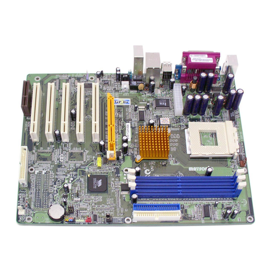
AC97 link compatible sound system and full System Management Bus (SMBus) interface. The MS8147C is equipped with advanced full set of I/O ports, such as dual channel IDE interfaces, a floppy controller, two high-speed serial port, an EPP/ECP capable bi-directional parallel port connector, four USB (Universal Serial Bus) connector, a PS/2 keyboard, mouse connectors. -
Page 6: Features
CPU to make sure that the “Ther- mal Diode” function will work properly. Chipset The chipset on MS8147C includes the KT400 Northbridge and VT8235 Southbridge which are based on an innovative and scal- able architecture with proven reliability and performance. A few of the chipset’s advanced fe atures are:... - Page 7 18-bit stereo full-duplex codec with independent and vari- able sampling rates. Further features include support for four analog line-level stereo inputs. Expansion MS8147C has five 32-bit PCI slots, an AGP slot (supports Options 1.5V 4x/8x AGP card only) and CNR (Communications and Networking Riser) slot.
-
Page 8: Choosing A Computer Case
BIOS This mainboard uses Award BIOS that enables users to con- Firmware figure many system features including the following: Power management Wake-up alarms CPU parameters CPU and memory timing The firmware can also be used to set parameters for different processor clock speeds. - Page 10 Table of Mainboard Components Label Component 1394J2 IEEE 1394A header AGP1 Accelerated Graphics Port (supports 1.5V 4x AGP card only) ATX1 Standard 20-pin ATX power connector AUDIO1 Front audio connector BAT1 Three volt realtime clock battery CASFAN1 Case fan connector Primary CD-in connector Secondary CD-in connector CHS1...
-
Page 11: Installing The Mainboard
Installing the Mainboard Follow these safety precautions when installing the mainboard: Wear a grounding strap attached to a grounded device to avoid damage from static electricity. Discharge static electricity by touching the metal case of a safely grounded object before working on the mainboard. Leave components in the static-proof bags they came in. -
Page 12: Installing The Mainboard In A Case
Refer to the following illustration and instructions for installing the mainboard in a case: This illustration shows an ex- 2. Secure the mainboard with ample of a mainboard being screws where appropriate. installed in a tower-type case: Note: Do not overtighten the screws as this can stress the main- board. -
Page 13: Checking Jumper Settings
Checking Jumper Settings The following illustration shows the location of the mainboard jumpers. Pin 1 is labeled. Jumper Settings Jumper Type Description Setting (default) 3-pin Clear CMOS 1-2: Normal 2-3: Clear CMOS JP3 & JP5 3-pin CPU Frequency See table on following select jumper page for settings. -
Page 14: Connecting Case Components
JP3 & JP5 – This jumper enables you to set the CPU frequency. CPU Frequency Short 1-2 Short 1-2 100MHz Short 2-3 Short 1-2 133MHz Short 1-2 Short 2-3 Not Applicable Short 2-3 Short 2-3 166MHz Connecting Case Components After you have installed the mainboard into a case, you can begin connecting the mainboard components. - Page 15 CPUFAN1/CASFAN1: FAN Power Connectors Signal Name Function System Ground +12V Power +12V Sense Sensor SPEAKER1: Internal speaker Signal Name Signal Ground CHS1: Chassis Intrusion Detect This connector allows the user to detect unauthorized intrusion to the case. It will alert the user with a warning message when the case is turned on. SJI: Single-color LED header Signal Name ACPI LED...
-
Page 16: Front Panel Connector
Front Panel Connector The front panel connector (PANEL1) provides a standard set of switch and LED connectors commonly found on ATX or micro-ATX cases. Refer to the table below for information: Signal Name Function HD_LED_P Hard disk LED pull up (330 ohm) to 5VSB MSG+ MSG LED pull up (330 ohm) to 5VSB... -
Page 17: Installing Hardware
Installing the Processor Caution: When installing a CPU heatsink and cooling fan make sure that you DO NOT scratch the mainboard or any of the surface-mount resistors with the clip of the cooling fan. If the clip of the cooling fan scrapes across the mainboard, you may cause serious damage to the mainboard or its components. -
Page 18: Cpu Installation Procedure
CPU Installation Procedure The following illustration shows CPU installation components: Note: The pin-1 corner is marked with an arrow Follow these instructions to install the CPU: Pull the CPU socket locking lever away from the socket to unhook it and raise the locking lever to the upright position. - Page 19 Connect the CPU Cooling Fan power cable connector to the CPUFAN connector. Note: CPU fan and heatsink installation procedures may vary with the type of CPU fan/heatsink supplied. The form and size of fan/heatsink may also vary. Installing Memory Modules This mainboard accommodates three 184-pin 2.5V unbuffered Double Data Rate (DDR) SDRAM memory modules.
-
Page 20: Installing Memory Modules
Align the memory module with the slot. The DIMM slots are keyed with notches and the DIMMs are keyed with cutouts so that they can only be i n - stalled correctly. Check that the cutouts on the DIMM module edge connector match the notches in the DIMM slot. -
Page 21: Installing A Hard Disk Drive/Cd-Rom
About IDE3 and IDE4 Devices The third and fourth IDE channels are provided for IDE RAID function. These channels are booted by hard disk drive only. Other device such as CD-ROM and ZIP does not support this function. For installing devices on IDE3 and IDE4, follow the same procedures for IDE1 and IDE2 “Installing a Hard Disk Drive”. - Page 22 Installing a CD-ROM/DVD Drive Install the CD-ROM/DVD drive into the drive cage in your system case. Plug the IDE cable into IDE1 (A). If you have already installed an HDD, use the other connec- tor on the IDE cable. Note: Ribbon cable connectors are usually keyed so that they can only be installed correctly on the device connector.
-
Page 23: Installing A Floppy Diskette Drive
Plug a power cable from the case power supply into the power connector on the FDD (C). When you first start up your system, go immediately to the Setup Utility to configure the floppy diskette drives t h at you have installed. See Standard CMOS Feature on page 29 for more information. -
Page 24: Connecting Optional Devices
Follow these instructions to install an add-on card: Remove a blanking plate from the system case corresponding to the slot you are going to use. Install the edge connector of the add-on card into the expansion slot. Ensure that the edge con- nector is correctly seated in the slot. - Page 25 AUDIO1: Front Panel Audio header This header allows the user to install auxiliary front-oriented microphone and line-out ports for easier access. Signal Name Function AUD_MIC Front Panel Microphone input signal AUD_GND Ground used by Analog Audio Circuits AUD_MIC_BIAS Microphone Power AUD_VCC Filtered +5 V used by Analog Audio Circuits AUD_FPOUT_R...
- Page 26 IR1: Serial infrared port The mainboard supports an Infrared (IR1) data port. Infrared ports allow the wireless exchange of information between your computer and similarly equipped devices such as printers, laptops, Personal Digital Assistants (PDAs), and other computers. Signal Name Function Not assigned Not assigned...
- Page 27 IDE3/IDE4: Third/Fourth IDE connector These connectors are for Promise PDC20265R controller only. Connect one cable to each of the IDE connectors of the mainboard (IDE3 & IDE4 connec- tor). Please note the color orientation of the cable before attaching it to the mainboard.
-
Page 28: Connecting I/O Devices
The backplane of the mainboard has the following I/O ports: PS/2 Mouse Use the upper PS/2 port to connect a PS/2 point- ing device. PS/2 Ke yboard Use the lower PS/2 port to connect a PS/2 key- board. LPT1 Use LPT1 to connect printers or other parallel communications devices. -
Page 29: External Connector Color Coding
External Connector Color Coding Many connectors now use standard colors as shown in the table below. Connector Color Audio line-in Light blue Audio line-out Lime Digital monitor/flat panel White IEEE 1394 Grey Microphone Pink MIDI/game Gold Parallel Burgundy PS/2-compatible keyboard Purple PS/2-compatible mouse Green... -
Page 30: Using Bios
Using BIOS The computer uses the latest Award BIOS with support for Windows Plug and Play. The CMOS chip on the mainboard contains the ROM setup instructions for configuring the mainboard BIOS. The BIOS (Basic Input and Output System) Setup Utility displays the system's configuration status and provides you with options to set system parameters. -
Page 31: Entering The Setup Utility
Entering the Setup Utility When you power on the system, BIOS enters the Power-On Self Test (POST) routines. POST is a series of built-in diagnostics performed by the BIOS. After the POST routines are completed, the following message appears: Press DEL to enter SETUP Pressing the delete key accesses the BIOS Setup Utility: Phoenix –... -
Page 32: Using Bios
If your mainboard has an item called Firmware Write Protect in Advanced BIOS features, disable it. (Firmware Write Protect prevents BIOS from being overwritten.) Create a bootable system disk. (Refer to Windows online help for infor- mation on creating a bootable system disk.) Download the Flash Utility and new BIOS file from the manufacturer's Web site. -
Page 33: Standard Cmos Feature
Standard CMOS Feature This option displays basic information about your system. Phoenix – AwardBIOS CMOS Setup Utility Standard CMOS Feature Item Help Date (mm:dd:yy) Tue, July 11 2001 Time (hh:mm:ss) 12 : 8 : 59 Menu Level IDE Primary Master Change the day, month, IDE Primary Slave year and century. - Page 34 IDE HDD Auto-Detection Press <Enter> while this item is highlighted to prompt the Setup Utility to automatically detect and configure an IDE device on the IDE channel. Note: If you are setting up a new hard disk drive that supports LBA mode, more than one line will appear in the parameter box.
-
Page 35: Advanced Bios Features
Advanced BIOS Features This option defines advanced information about your system . Phoenix – AwardBIOS CMOS Setup Utility Advanced BIOS Features Item Help CPU Internal Cache [Enabled ] External Cache [Enabled] Menu Level CPU L2 Cache ECC Checking [Enabled] Processor Number Feature [Enabled] Allows you to choose Quick Power On Self Test... - Page 36 First/Second/Third Boot Device (Floppy/HDD-0/CD-ROM) Use these three items to select the priority and order of the devices that your system searches for an operating system at start-up time. Boot Other Device (Enabled) When enabled, the system searches all other possible locations for an operat- ing system if it fails to find one in the devices specified under the First, Second, and Third boot devices.
-
Page 37: Advanced Chipset Features
OS Select For DRAM > 64 MB (Non-OS2) This item is only required if you have installed more than 64 MB of memory and you are running the OS/2 operating system. Otherwise, leave this item at the default. HDD S.M.A.R.T Capability (Disabled) The S.M.A.R.T. - Page 38 DRAM Clock/Drive Control Scroll to this item and press <Enter> to view the following screen: Phoenix – AwardBIOS CMOS Setup Utility DRAM Clock/Drive Control Item Help Current FSB Frequency Current DRAM Frequency Menu Level DRAM Clock [By SPD] DRAM Timing [Auto by SPD] DRAM CAS Latency [2.5]...
- Page 39 Precharge to Active (3T/4T) This item is used to designate the minimum Row Precharge time of the SDRAM devices on the module. DRAM must continually be refreshed or it will lose its data. Normally, DRAM is refreshed entirely as the result of a single request. This option allows you to de- termine the number of CPU clocks allocated for the Row Address Strobe (RAS) to accumulate its charge before the DRAM is refreshed.
- Page 40 AGP & P2P Bridge Control Scroll to this item and press <Enter> to view the following screen: Phoenix – AwardBIOS CMOS Setup Utility AGP & P2P Bridge Control Item Help AGP Aperture Size [125 MB] AGP Mode [4X] Menu Level AGP Driving Control [Auto] AGP Driving Value...
- Page 41 Press <Esc> to return to the Advanced Chipset Features screen. CPU & PCI Bus Control Scroll to this item and press <Enter> to view the following screen: Phoenix – AwardBIOS CMOS Setup Utility CPU & PCI Bridge Control Item Help PCI1 Master 0 WS Write [Enabled ] PCI2 Master 0 WS Write...
-
Page 42: Integrated Peripherals
Integrated Peripherals These options display items that define the operation of peripheral compo- nents on the system's input/output ports. Phoenix – AwardBIOS CMOS Setup Utility Integrated Peripherals Item Help VIA OnChip IDE Device [Press Enter] VIA OnChip PCI Device [Press Enter] Menu Level VIA Super I/O Device [Press Enter]... - Page 43 field to Disabled if the interface does not support prefetching. IDE Primary/Secondary Master/Slave PIO (Auto) Each IDE channel supports a master device and a slave device. These four items let you assign which kind of PIO (Programmed Input/Output) is used by IDE devices.
- Page 44 network add-in card with a remote boot ROM installed. Press <Esc> to return to the Integrated Peripherals screen. SuperIO Device Scroll to this item and press <Enter> to view the following screen: Phoenix – AwardBIOS CMOS Setup Utility SuperIO Device Item Help Onboard FDC Controller [Enabled ]...
- Page 45 Onboard Parallel Port (378/IRQ7) This option is used to assign the I/O address and interrupt request (IRQ) for the onboard parallel port. Parallel Port Mode (ECP) Enables you to set the data transfer protocol for your parallel port. There are four options: SPP (Standard Parallel Port), EPP (Enhanced Parallel Port), ECP (Extended Capabilities Port) and ECP+EPP.
-
Page 46: Power Management Setup
ables BIOS to automatically detect the optimal number of block read and writes per sector that the drive can support and improves the speed of access to IDE devices. PWRON After PWR-Fail (Off) This item enables your computer to automatically restart or return to its last operating status after power returns from a power failure. - Page 47 Note: ACPI is a power management specification that makes hardware status in- formation available to the operating system. ACPI enables a PC to turn its peripherals on and off for improved power management. It also allows the PC to be turned on and off by external devices, so that mouse or keyboard activity wakes up the computer.
- Page 48 IRQ/Event Activity Detect Scroll to this item and press <Enter> to view the following screen: Phoenix – AwardBIOS CMOS Setup Utility IRQ/Event Activity Detect Item Help PS2KB WakeUp from S3/S4/S5 [Disabled ] PS2KB Wakeup Select [Hot key] Menu Level PS2MS Wakeup from S3/S4/S5 [Disabled] USB Resume from S3 [Disabled]...
- Page 49 PCI Master (OFF) When set to Off, any PCI device set as the Master will not power on the sys- tem. PowerOn by PCI Card (Enabled) Use this item to enable PCI activity to wakeup the system from a power sav- ing mode.
-
Page 50: Pnp/Pci Configurations
PNP/PCI Configurations These options configure how PnP (Plug and Play) and PCI expansion cards oper- ate in your system. Both the ISA and PCI buses on the Mainboard use system IRQs (Interrupt ReQuests) and DMAs (Direct Memory Access). You must set up the IRQ and DMA assignments correctly through the PnP/PCI Configurations Setup utility for the mainboard to work properly. -
Page 51: Pc Health Status
expansion card. Use the second item Reserved Memory Length to set the amount of reserved memory. Press <Esc> to close the Memory Resources sub-menu. PCI/VGA Palette Snoop (Disabled) This item is designed to overcome some problems that can be caused by some non-standard VGA cards. -
Page 52: Frequency/Voltage Control
Frequency/Voltage Control This item enables you to set the clock speed and system bus for your system. The clock speed and system bus are determined by the kind of processor you have installed in your system. Phoenix – AwardBIOS CMOS Setup Utility Frequency/Voltage Control Item Help Auto Detect DIMM/PCI Clk... -
Page 53: Load Fail-Safe Defaults
Load Fail-Safe Defaults This option opens a dialog box that lets you install fail-safe defaults for all ap- propriate items in the Setup Utility: Press <Y> and then <Enter> to install the defaults. Press <N> and then <En- ter> to not install the defaults. The fail-safe defaults place no great demands on the system and are generally stable. -
Page 54: Save & Exit Setup
Save & Exit Setup Highlight this item and press <Enter> to save the changes that you have made in the Setup Utility and exit the Setup Utility. When the Save and Exit dialog box appears, press <Y> to save and exit, or press <N> to return to the main menu: Exit Without Saving Highlight this item and press <Enter>... -
Page 55: Using The Mainboard Software
Using the Mainboard Software The support software CD-ROM that is included in the mainboard package contains all the drivers and utility programs needed to properly run the bun- dled products. Below you can find a brief description of each software program, and the location for your mainboard version. -
Page 56: Utility Software Reference
All the utility software available on the CD-ROM is Windows compliant. It is provided only for the convenience of customers. The following software is furnished under license and may only be used or copied in accordance with the terms of the license. Note: The software in these folders is subject to change at anytime without prior notice. - Page 57 PageABC The PageABC application software enables you to create your own home page. To install the PageABC, run SETUP.EXE from the following directory: \UTILITY\PageABC This concludes Chapter 4.
Need help?
Do you have a question about the MS8147C and is the answer not in the manual?
Questions and answers