Table of Contents
Advertisement
Quick Links
Mainboard User's Manual
This publication, including all photographs, illustrations and
software, is protected under international copyright laws, with all
rights reserved. Neither this manual, nor any of the material
contained herein, may be reproduced without written consent of the
author.
The information in this document is subject to change without
notice. The manufacturer makes no representations or warranties
with respect to the contents hereof and specifically disclaims any
implied warranties of merchantability or fitness for any particular
purpose. Further, the manufacturer reserves the right to revise this
publication and to make changes from time to time in the content
hereof without obligation of the manufacturer to notify any person
of such revision or changes.
Trademarks
IBM, VGA, and PS/2 are registered trademarks of International
Business Machines.
Intel, Pentium/II/III, Pentium 4, Celeron and MMX are registered
trademarks of Intel Corporation.
Microsoft, MS-DOS and Windows 98/ME/NT/2000/XP are
registered trademarks of Microsoft Corporation.
PC-cillin is a registered trademark of Trend Micro Inc.
AMI is a registered trademark of American Megatrends Inc.
MediaRing Talk is a registered trademark of MediaRing Inc.
3Deep is a registered trademark of E-Color Inc.
st
st
Recovery Genius 21
, CD Ghost and Language Genius 21
are
trademarks of GoldenSoft Technology Co., Ltd.
SiS is a trademark of Silicon Integrated System Corporation.
Other names used in this publication may be trademarks and are
acknowledgedledged.
Copyright © 2002
All Rights Reserved
MS8328E Series, V2.1
S740/November 2002
Advertisement
Table of Contents

Related Manuals for MATSONIC MS8328E Series


Summary of Contents for MATSONIC MS8328E Series
- Page 1 , CD Ghost and Language Genius 21 trademarks of GoldenSoft Technology Co., Ltd. SiS is a trademark of Silicon Integrated System Corporation. Other names used in this publication may be trademarks and are acknowledgedledged. Copyright © 2002 All Rights Reserved MS8328E Series, V2.1 S740/November 2002...
- Page 2 Mainboard User’s Manual Notice: Owing to Microsoft’s certifying schedule is various to every supplier, we might have some drivers not certified yet by Microsoft. Therefore, it might happen under Windows XP that a dialogue box (shown as below) pop out warning you this software has not passed Windows Logo testing to verify its compatibility with Windows XP.
-
Page 3: Table Of Contents
Mainboard User’s Manual Table of Contents Trademarks................ I Chapter 1: Introduction .............. 1 Key Features..............2 Package Contents ...............5 Static Electricity Pre cautions..........6 Pre-Installation Inspection...........6 Chapter 2: Mainboard Installation ..........7 Mainboard Components............8 I/O Ports................9 Install A CPU..............9 Install Memory ..............11 Setting Jumper Switches ...........12 Install the Mainboard............ - Page 4 Mainboard User’s Manual...
-
Page 5: Chapter 1: Introduction
1: Introduction Chapter 1 Introduction This mainboard has a Socket-462 processor socket for the AMD K7 type of processors. You can install any of these processors on this mainboard. This mainboard supports front-side bus speed of 266MHz. This mainboard integrates the SiS740 Northbridge and SiS962/962L Southbridge chipsets that support a DDR interface, Ultra DMA 66/100/133 function and remarkably high system performance under all types of system operations. -
Page 6: Key Features
Mainboard User’s Manual Key Features The key features of this mainboard include: Socket-462 Processor Support ♦ Supports AMD Athlon XP/Athlon/Duron processors ♦ Supports 200/266 MHz Front-Side Bus Memory Support ♦ Three 184-pin DIMM sockets (DDR1 ~ DDR3) for DDR memory modules ♦... - Page 7 1: Introduction AC97 Audio Codec: CMI9738 ♦ Compliant with AC’97 2.2 specification ♦ Full-duplex Codec with independent and variable sampling rate ♦ Earphone Buffer Built-In, SNR up to 90db ♦ 4Ch DAC, support 4-channel speak-out ♦ Advanced power management support Built-in Ethernet LAN ♦...
- Page 8 Mainboard User’s Manual ♦ Compliant with Intel’s Enhanced Host Controller Interface Specification Revision 0.95 ♦ Compliant with Universal Host Controller Interface Specification Revision 1.1 ♦ PCI multi-function device consists of two UHCI Host Controller cores for full-/low-speed signaling and one EHCI Host Controller core for high-speed signaling ♦...
-
Page 9: Package Contents
1: Introduction ♦ PageABC is the software to help you create your own home page. Dimensions ♦ Micro ATX form factor (220mm x 244mm) Package Contents Your mainboard package ships with the following items: The mainboard This User’s Guide 1 UDMA66/100 IDE cable 1 Floppy disk drive cable Support software on CD-ROM disk Optional Accessories... -
Page 10: Static Electricity Precautions
Mainboard User’s Manual Static Electricity Precautions Static electricity could damage components on this mainboard. Take the following precautions while unpacking this mainboard and installing it in a system. 1. Don’t take this mainboard and components out of their original static-proof package until you are ready to install them. 2. -
Page 11: Chapter 2: Mainboard Installation
2: Mainboard Installation Chapter 2 Mainboard Installation To install this mainboard in a system, please follow the instructions in this chapter: Identify the mainboard components Install a CPU Install one or more system memory modules Verify that all jumpers or switches are set correctly Install the mainboard in a system chassis (case) Connect any extension brackets or cables to connecting headers on the mainboard... -
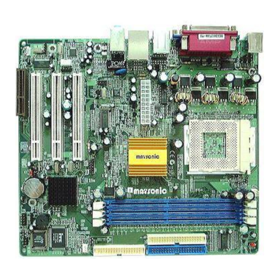
Page 12: Mainboard Components
Mainboard User’s Manual Mainboard Components This diagram below identifies major components on the mainboard. Note: Any jumpers on your mainboard that do not appear in the illustration above are for testing only. -
Page 13: I/O Ports
2: Mainboard Installation I/O Ports The illustration below shows a side view of the built-in I/O ports on the mainboard. Install A CPU This mainboard has a Socket-462 that supports AMD K7 processors. To ensure reliability, ensure that your processor has a heatsink/cooling fan assembly. - Page 14 Mainboard User’s Manual Installing a Socket-462 Processor Install a processor into the ZIF (Zero Insertion Force) Socket-462 on the mainboard. 1. Locate the Socket-462 and CPUFAN. Unlock the socket by pressing the locking lever slightly sideways, and then lift it to the upright position.
-
Page 15: Install Memory
2: Mainboard Installation Install Memory This mainboard accommodates three184-pin 2.5V unbuffered Double Data Rate (DDR) SDRAM DIMM sockets. You must install at least one memory module in order to work out the mainboard. When you install DDR200/DDR266 memory modules, the memory bus can run up to 100/133 MHz. -
Page 16: Setting Jumper Switches
Mainboard User’s Manual Setting Jumper Switches Jumpers are sets of pins that can be connected together with jumper caps. Jumper caps change the operating way of the mainboard by changing the electronic circuits. If a jumper cap connects two pins, these pins are SHORT; if it is removed, these pins are OPEN. -
Page 17: Install The Mainboard
2: Mainboard Installation Install the Mainboard Install the mainboard in a system chassis (case). The board is an Micro ATX size mainboard with a twin-tier of I/O ports. You can install this mainboard in an ATX case. Ensure that your case has an I/O cover plate that matches the ports on this mainboard. - Page 18 Mainboard User’s Manual Connect the case switches and indicator LEDs to the SW1 header. Here is a list of SW1 header’s pin assignments: Signal Signal HD_LED_P FP PWR/SLP HD_LED_N FP PWR/SLP RESET_SW_N POWER_SW_P RESET_SW_P POWER_SW_N RSVD_DNU If there are a headphone jack or/and a microphone jack on the front panel, connect the cables to the AUDIO1 header on the mainboard.
-
Page 19: Optional Extension Brackets
2: Mainboard Installation Optional Extension Brackets For this mainboard, you can also obtain a USB module extension bracket for more USB ports. Install them by following the steps below. Note: All the ribbon cables used on the extension brackets have a red stripe on the Pin -1 side of the cable. - Page 20 Mainboard User’s Manual Extended IEEE1394a Header (Optional) You can obtain one optional IEEE1394a header, and install them by following the steps below. Signal Signal CPWR XTPB0M XTPB0P XTPA0M XTPA0P SHIELD 1. Locate the JP2 header on the mainboard. 2. Plug the bracket cable onto the JP2 header. 3.
-
Page 21: Install Other Devices
2: Mainboard Installation Install Other Devices Install and connect any other devices in the system following the steps below. FDC1 IDE2 IDE1 Floppy Disk Drive The mainboard ships with a floppy disk drive cable that can support one or two drives. Drives can be 3.5” or 5.25” wide, with capacities of 360K, 720K, 1.2MB, 1.44MB, or 2.88MB. - Page 22 Mainboard User’s Manual Install the device(s) and connect power from the system power supply. Use the cable provided to connect the device(s) to the Primary IDE channel connector IDE1 on the mainboard. If you want to install more IDE devices, you can purchase a second IDE cable and connect one or two devices to the Secondary IDE channel connector IDE2 on the mainboard.
-
Page 23: Expansion Slots
2: Mainboard Installation Infrared Port You can connect an infrared port to the mainboard. You can purchase this option from third-party vendors. 1. Locate the infrared port IR1 header on the mainboard. 2. If you are adding an infrared port, connect the ribbon cable from the port to the IR1 header and then secure the port to an appropriate place in your system chassis. - Page 24 Mainboard User’s Manual...
-
Page 25: Chapter 3: Bios Setup Utility
3: BIOS Setup Utility Chapter 3 BIOS Setup Utility Introduction The BIOS Setup Utility records computer’s settings and information, such as date and time, type of installed hardware, and various configuration settings. Your computer applies the information to initialize all the components when booting up, and basic functions of overall coordination between system components. -
Page 26: Running The Setup Utility
Mainboard User’s Manual Running the Setup Utility Each time your computer starts, before the operating system loads, a message appears on the screen that prompts you to “Hit <DEL> if you want to run SETUP”. When you see this message, press the Delete key and the Main menu page of the Setup Utility appears on your monitor. -
Page 27: Standard Cmos Setup Page
3: BIOS Setup Utility Standard CMOS Setup Page Use this page to set basic information such as the date, the time, the IDE devices, and the diskette drives. If you press the F3 key, the system will automatically detect and configure the hard disks on the IDE channels. -
Page 28: Advanced Setup Page
Mainboard User’s Manual Advanced Setup Page This page sets up more advanced information about your system. Take care with this page with more caution. Making changes can affect the operation of your computer. AMIBIOS SETUP – ADVANCED SETUP (C) 2000 American Megatrends, Inc. All Rights Reserved Share Memory Size 32MB Quick Boot... - Page 29 3: BIOS Setup Utility Floppy Drive If you have two diskette drives installed and you Swap enable this item, drive A becomes drive B and drive B becomes drive A. Floppy Drive If you enable this item, your system will check all Seek floppy disk drives at start up.
-
Page 30: Power Management Setup Page
Mainboard User’s Manual Power Management Setup Page This page sets up some of the parameters for system power management operation. AMIBIOS SETUP – POWER MANAGEMENT SETUP (C) 2000 American Megatrends, Inc. All Rights Res erved ACPI Aware O/S Power Management Enabled Suspend Time Out Disabled... -
Page 31: Pci / Plug And Play Setup Page
3: BIOS Setup Utility LAN/Ring Power Your syste m can enter a software power down. If you enable this item, the system can automatically resume if there is traffic on the network adapter. Keyboard Power If you enable this item, you can turn the system on and off by pressing hot keys on the keyboard. -
Page 32: Load Optimal Settings
Mainboard User’s Manual Load Optimal Settings If you select this item and press Enter a dialog box appears. If you press Y, and then Enter, the Setup Utility loads a set of fail-safe default values. These default values are not very demanding and they should allow your system to function with most kinds of hardware and memory chips. - Page 33 3: BIOS Setup Utility OnBoard Serial These items enable or disable the onboard COM1 PortA serial port, and to assign a port address. OnBoard Ir Port Use this item to define the protocol for an infrared port if you have installed an optional IR port. The options are IrDA and ASKIR.
-
Page 34: Cpu Pnp Setup Page
Mainboard User’s Manual CPU PnP Setup Page This page lets you manually configure the mainboard for the CPU. The system will automatically detect the kind of CPU that you have installed and make the appropriate adjustments to the items on this page. AMIBIOS SETUP –... -
Page 35: Hardware Monitor Page
3: BIOS Setup Utility Hardware Monitor Page This page sets some of the parameters for the hardware monitoring function of this mainboard. AMIBIOS SETUP – HARDWARE MONITOR (C) 2000 American Megatrends, Inc. All Rights Reserved *** System Hardware *** Vcore 1.632V Vcc 2.5V 2.496V... -
Page 36: Exit
Mainboard User’s Manual Change or Remove the Password Highlight this item, press Enter and type in the current password. At the next dialog box, type in the new password, or just press Enter to disable password protection. Exit Highlight this item and press Enter to save the changes that you have made in the Setup Utility configuration and exit the program. -
Page 37: Chapter 4: About The Software Cd-Rom
4: Software & Applications Chapter 4 About the Software CD-ROM The support software CD-ROM that is included in the mainboard package contains all the drivers and utility programs needed to properly run the bundled products. Below you can find a brief description of each software program, and the location for your mainboard version. -
Page 38: Utility Software Reference
Mainboard User’s Manual Utility Software Reference All the utility software available on the CD-ROM is Windows compliant. It is provided only for the convenience of customers. The following software is furnished under license and may only be used or copied in accordance with the terms of the license. - Page 39 4: Software & Applications Super Voice – Fax/Modem Software To install the Super Voice voice, fax, data communication application for use with the built-in fax/modem, run PICSHELL.EXE from the following directory: \UTILITY\SUPER VOICE CD Ghost The CD Ghost software enables you to create a virtual cabinet of CD-ROM drives on your system to help you categorize and organize your CD collection.
Need help?
Do you have a question about the MS8328E Series and is the answer not in the manual?
Questions and answers