Advertisement
Notice
The information in this guide is subject to change without notice.
Compaq Computer Corporation shall not be liable for technical or editorial
errors or omissions contained herein; nor for incidental or consequential
damages resulting from the furnishing, performance, or use of this
material.
This guide contains information protected by copyright. No part of this
guide may be photocopied or reproduced in any form without prior written
consent from Compaq Computer Corporation.
Copyright 1994 Compaq Computer Corporation.
All rights reserved. Printed in the USA.
Compaq, Deskpro, LTE, Contura
Registered U.S. Patent and Trademark Office.
Contura Aero is a trademark of Compaq Computer Corporation.
The software described in this guide is furnished under a license agreement
or nondisclosure agreement. The software may be used or copied only in
accordance with the terms of the agreement.
Product names mentioned herein may be trademarks and/or registered
trademarks of their respective companies.
MAINTENANCE AND SERVICE GUIDE
Compaq Contura Aero Family of Personal Computers
First Edition (February 1994)
Part Number 197235-001
Advertisement
Table of Contents

Related Manuals for Compaq CONTURA AERO


Summary of Contents for Compaq CONTURA AERO
- Page 1 Notice The information in this guide is subject to change without notice. Compaq Computer Corporation shall not be liable for technical or editorial errors or omissions contained herein; nor for incidental or consequential damages resulting from the furnishing, performance, or use of this material.
- Page 2 COMPAQ SERVICE QUICK REFERENCE GUIDE o Service Training Guides o Compaq Service Advisories and Bulletins Compaq Computer Corporation reserves the right to make changes to the Compaq Contura Aero Family of Personal Computers without notice. Symbols The following words and symbols mark special messages throughout this guide: >>>>>>>>>>>>>>>>>>>>>>>>>>>>>>>>>...
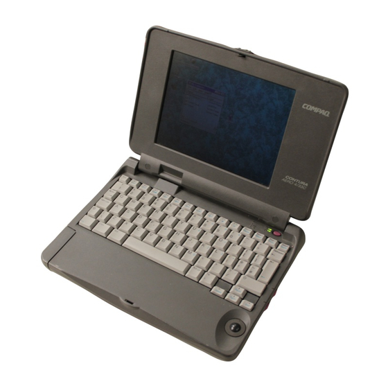
- Page 3 Chapter 1. Illustrated Parts Catalog Chapter 1.0 Introduction Chapter 1.1 Illustrated Parts Breakdown: Compaq Contura Aero Family Of Personal Computers The Compaq Contura Aero Family of Personal Computers joins a display assembly and system unit together with a clutch secured by screws in the chassis, display enclosure, and a display pin allowing it to open and close.
- Page 4 o PCMCIA ejector rails o Trackball assembly o Memory expansion board (optional) o System board The keyboard is secured to the system unit with four screws and a hook latch in the front. Once the screws are removed, the keyboard must be rotated from the rear forward to disengage it from the hook latch.
- Page 5 Compaq Contura Aero 4/25 The display assembly is secured with two screws in the bottom corners of the display bezel and by a screw in a clutch and a pin to the base enclosure. To remove the display assembly from the base enclosure, the display bezel must be removed first.
- Page 7 Chapter 1.2 System Unit Module...
- Page 8 Spare Part No. Notes =========================================================================== Base enclosure 197253-001 Includes screw covers. --------------------------------------------------------------------------- System board, 4 MB Does not include PCMCIA ejector rails. Compaq Contura 197241-001 Includes screw covers. Aero 4/25 Compaq Contura 199222-001 Aero 4/33C --------------------------------------------------------------------------- Door assembly 197239-001 Includes battery and memory expansion board doors.
-
Page 9: Chapter 1.3 Vga Display
- 4 MB 190565-001 - 8 MB 190596-001 --------------------------------------------------------------------------- Real time clock 117099-001 battery --------------------------------------------------------------------------- NiMH Battery Pack - 8A: Extended Life 190626-001 Extended Life battery does not - 8B: Standard 190697-001 include spacer. Standard battery - 8C: Spacer 197317-001 includes spacer. - Page 10 Table 1-2. Compaq Contura Aero 4/25 Monochrome VGA Display =========================================================================== Description Spare Part No. Notes =========================================================================== Display enclosure 197237-001 Includes enclosure, clutch, pin, latch, spring, screws, display shield, slotted bushing, ground clip, screw covers and logo. --------------------------------------------------------------------------- Display panel 190624-001 Includes labels, screw covers.
- Page 11 Table 1-3. Compaq Contura Aero 4/33C Color VGA Display =========================================================================== Description Spare Part No. Notes =========================================================================== Display enclosure 199257-001 Includes enclosure, clutch, pin, latch, spring, screws, display shield, slotted bushing, screw covers and logo. --------------------------------------------------------------------------- Display panel 199232-001 Includes labels, screw covers.
- Page 12 Chapter 1.4 Keyboards Table 1-4. Notebook Keyboards =========================================================================== Description Spare Part Number =========================================================================== U.S. 190620-001 U.K. 190620-003 * German 190620-004 * French 190620-005 * Italian 190620-006 * Spanish 190620-007 * Danish 190620-008 * Norwegian 190620-009 * Swedish/Finnish 190620-010 * Swiss 190620-011 * French Canadian 190620-012 *...
- Page 13 =========================================================================== Description Spare Part Number =========================================================================== Enhanced II Keyboard U.S. 112573-001 (No longer available)* Enhanced III Keyboard U.K. 140536-103 * Enhanced III Keyboard German 140536-104 * Enhanced III Keyboard French 140536-105 * Enhanced III Keyboard Italian 140536-106 * Enhanced III Keyboard Spanish 140536-107 * Enhanced III Keyboard Danish 140536-108 *...
-
Page 14: Chapter 1.6 Ac Adapter And Power Cord
Table 1-6. Cables =========================================================================== Description Spare Part Number =========================================================================== Display Cable (Compaq Contura Aero 4/25) 197238-001 Trackball/Speaker Cable 197312-001 Communication Cable 197318-001 Display Cable (Compaq Contura Aero 4/33C) 199258-001 =========================================================================== Chapter 1.6 AC Adapter And Power Cord... - Page 15 Table 1-7. AC Adapter and Power Cord =========================================================================== Description Spare Part Number =========================================================================== AC Adapter 190621-001 Power Cord (U.S./Canada) 197230-001 Power Cord (U.K.) 197232-001 * Power Cord (Europe) 197231-001 * Power Cord (Japan) 197233-001 * Power Cord (Asia Pacific) 197234-001 * --------------------------------------------------------------------------- * Not shown ===========================================================================...
- Page 16 --------------------------------------------------------------------------- COMPAQ SERVICE QUICK REFERENCE GUIDE 106854-001 --------------------------------------------------------------------------- LOTUS ORGANIZER MANUAL English 137885-001 German 137885-041 French 137885-051 Italian 137885-061 Spanish 137885-071 --------------------------------------------------------------------------- Online USER'S GUIDE English 190512-001 German 190512-041 French 190512-051 Italian 190512-061 Spanish 190512-071 --------------------------------------------------------------------------- WINLINK (diskettes) English 197330-001...
- Page 17 144865-003 T8/SL --------------------------------------------------------------------------- M2.5 x 16.0 Truss Base 144865-005 T8/SL --------------------------------------------------------------------------- * Screwlocks =========================================================================== Table 1-11b. Fastener List for the Compaq Contura Aero 4/25 Display =========================================================================== Description Type Where Used Part Number Drive =========================================================================== M2.0 x 4.0 Truss 144863-001 T8/SL M2.5 x 4.5...
- Page 18 CPU enclosure feet 197345-001 Battery and memory doors 197239-001 PCMCIA eject rails 197314-001 Carton, quantity 5 137863-001 Carton and buns, quantity 1 137864-001 Display connector slider 140071-001 Plate logo 197251-001 Battery spacer 197317-001 ===========================================================================...
- Page 19 Chapter 2. Service Preliminaries Chapter 2.0 Introduction This chapter provides general service information for the computer and the base unit. Adherence to the procedures and precautions described in this chapter is essential for proper service. Chapter 2.1 Electrostatic Discharge (International) A sudden discharge of static electricity from a finger or other conductor can destroy static sensitive devices or micro circuitry.
- Page 20 structure determine the degree of sensitivity. The following proper packaging and grounding precautions are necessary to prevent damage: o Protect all electrostatic parts and assemblies with conductive or approved containers or packaging. o Keep electrostatic sensitive parts in their containers until they arrive at static free stations.
- Page 21 To prevent static damage at the workstation, use the following precautions: o Cover the workstation with approved static dissipative material. Provide a wrist strap connected to the work surface and properly grounded tools and equipment. o Use static dissipative mats, heel straps, or air ionizers to give added protection.
- Page 22 o Conductive bins, and other assembly or soldering aids o Conductive foam o Conductive table top workstations with ground cord of 1 megohm of resistance o Static dissipative table or floor mats with hard tie to ground o Field service kits o Static awareness labels o Wrist straps and footwear straps providing 1 megohm +/- 10% resistance o Material handling packages...
- Page 23 The screws used in these products are not interchangeable. If an incorrect screw is used during the reassembly process, it could cause damage to the unit. Compaq strongly recommends that all screws removed during the disassembly process be kept with the part that was removed, then returned to their proper locations.
- Page 26 Plastics The plastics used can be damaged by application of excessive force during disassembly and reassembly. When handling the plastic cases and housing assemblies, use care. Do not use screwdrivers or similar tools to pry apart plastics. Where necessary, use the Case utility tool (spare part number 119070-001).
- Page 27 A sudden discharge of static electricity from a finger or other conductor can destroy static sensitive devices or micro circuitry. Often the spark is neither felt or heard, but damage occurs. An electronic device exposed to electrostatic discharge (ESD) may not be affected at all and will work perfectly throughout a normal cycle.
- Page 28 o Place reusable electronic sensitive parts from assemblies in protective packaging or conductive foam. Use transporters and conveyors made of antistatic belts and metal roller bushings. Mechanized equipment used for moving materials must be wired to ground and proper materials selected to avoid static charging. When grounding is not possible, use an ionizer to dissipate electric charges.
- Page 29 o Turn off power and input signals before inserting and removing connectors or test equipment. o Use fixtures made of static safe materials when fixtures must directly contact dissipative surfaces. o Keep work area free of nonconductive materials such as ordinary plastic assembly aids and Styrofoam.
- Page 30 The screws used in these products are not interchangeable. If an incorrect screw is used during the reassembly process, it could cause damage to the unit. Compaq strongly recommends that all screws removed during the disassembly process be kept with the part that was removed, then returned to their proper locations.
- Page 31 Cables and Connectors Most cables used throughout the unit are flex cables (Figures 2-1, 2-2, 2-3). These cables must be handled with extreme care to avoid damage. Apply only the tension required to seat or unseat the cables during insertion or removal from the connector.
- Page 33 >>>>>>>>>>>>>>>>>>>>>>>>>>>>>>>>>>>>><<<<<<<<<<<<<<<<<<<<<<<<<<<<<<<<<<<<<< Compaq offers its portable product customers an environmentally sound method for disposing of depleted Compaq rechargeable battery packs used in Compaq laptop and subnotebook personal computers.
- Page 34 "battery mailer" envelope preaddressed to the reclamation facility. Place the Compaq rechargeable battery pack into the battery mailer and mail it to the Compaq address shown on the mailer. Do not return Compaq rechargeable battery packs to Authorized Compaq Service Providers (except in the case of service or warranty exchanges) nor to any Compaq address other than the address on the preaddressed battery mailer envelope.
- Page 35 Chapter 3.0 Introduction This chapter provides subassembly/module level removal and replacement procedures for the Compaq Contura Aero Family of Personal Computers. After completing all necessary removal and replacement procedures, run the diagnostics program to verify that all components operate properly.
-
Page 36: Chapter 3.4 Removing The Battery Pack
1. Turn off the power switch on the computer. >>>>>>>>>>>>>>>>>>>>>>>>>>>>>>>>> CAUTION <<<<<<<<<<<<<<<<<<<<<<<<<<<<<<<<< Turn off the computer before any cables are connected or disconnected. >>>>>>>>>>>>>>>>>>>>>>>>>>>>>>>>>>>>><<<<<<<<<<<<<<<<<<<<<<<<<<<<<<<<<<<<<< 2. Disconnect all external devices (diskette drive, base unit, printer, and other devices) from the computer. 3. - Page 37 3. Remove the battery pack by gently pulling it out of the battery compartment >>>>>>>>>>>>>>>>>>>>>>>>>>>>>>>>> CAUTION <<<<<<<<<<<<<<<<<<<<<<<<<<<<<<<<< Metal objects will damage the battery pack as well as the connectors in the compartment. To prevent damage, do not let metal objects touch any of the connectors.
- Page 38 1. Align the slot in the battery pack with the rib inside the computer. 2. Insert the battery pack, with the battery contacts facing to the inside of the battery compartment. 3. Push firmly on the battery pack until it slides into place. 4.
- Page 39 6. Slide the latch on the front of the computer to the right and open the display (Figure 3-4). 7. Remove the screw covers from the bottom right and left corners of the display panel assembly. Using a Phillips screwdriver, remove the two screws (Figure 3-5).
- Page 40 8. Remove the bezel from the display assembly by gently pulling the bezel frame and working from the bottom up (Figure 3-6).
- Page 41 9. Unsnap the CPU cover with the Case utility tool and lift it off of the computer (Figure 3-7).
-
Page 42: Chapter 3.6 Removing The Keyboard
To replace the CPU cover, reverse the previous steps. >>>>>>>>>>>>>>>>>>>>>>>>>>>>>>>>> CAUTION <<<<<<<<<<<<<<<<<<<<<<<<<<<<<<<<< When replacing the CPU cover, be sure not to pinch the trackball cables on the right side of the cover (see Figure 3-41). >>>>>>>>>>>>>>>>>>>>>>>>>>>>>>>>>>>>><<<<<<<<<<<<<<<<<<<<<<<<<<<<<<<<<<<<<< Chapter 3.6 Removing The Keyboard To remove the keyboard, follow these steps: 1. - Page 43 4. Gently lift up on the rear of the keyboard and unhook it from the hook latches in the front (Figure 3-9).
- Page 44 5. Rotate the rear of the keyboard toward you until the two ZIF connectors are exposed and lay the keyboard upside down on top of the battery compartment (Figure 3-10). NOTE: You may not have to disconnect the cables from the keyboard to have access to the component you want to remove and/or replace.
- Page 45 (Figure 3-10). Chapter 3.7 Removing The VGA Backlit Display Compaq Contura Aero 4/25 Display To remove the monochrome VGA backlit display from the Compaq Contura Aero 4/25 Personal Computer, follow these steps: 1. Remove the battery pack (Section 3.4). 2. Remove the display bezel and the CPU cover (Section 3.5).
- Page 46 3. Remove the keyboard (Section 3.6). 4. Release the ZIF slider attaching the display cable to the system board. NOTE: It may not be necessary to remove the display assembly from the base enclosure to service the system board. The display will support itself in an open position without falling over.
- Page 47 >>>>>>>>>>>>>>>>>>>>>>>>>>>>>>>>> CAUTION <<<<<<<<<<<<<<<<<<<<<<<<<<<<<<<<< Do not bend the support loop. >>>>>>>>>>>>>>>>>>>>>>>>>>>>>>>>>>>>><<<<<<<<<<<<<<<<<<<<<<<<<<<<<<<<<<<<<< 6. Lift the display assembly out of the computer by sliding it to the right to pull the display pin out of the support loop. (Figure 3-13).
- Page 48 To replace the display assembly, follow these steps: 1. Position the display assembly by aligning the display clutch and pin with the support loop and keyed bushing (Figure 3-14).
- Page 49 2. Reattach the screw to the base enclosure and clutch. To reconnect the display cable to the system board, follow these steps (Figure 3-15): 1. Insert the display cable into the ZIF connector and lightly press the slider down to lock the connector. 2.
- Page 50 Display Inverter Board To remove the display inverter board, follow these steps: 1. Remove the display bezel (Figures 3-5 and 3-6). 2. Remove the display cable and the backlight cable from the display inverter board in the bottom of the display enclosure by gently pulling the cables toward you, then unplugging from the inverter board LIF connector (Figure 3-16).
- Page 51 3. Lift the inverter board out of the display enclosure (Figure 3-17).
- Page 52 >>>>>>>>>>>>>>>>>>>>>>>>>>>>>>>>> CAUTION <<<<<<<<<<<<<<<<<<<<<<<<<<<<<<<<< When servicing these units, ensure that cables are placed in their proper location to avoid pinching during the reassembly process. Improper cable placement can cause severe damage to the unit. >>>>>>>>>>>>>>>>>>>>>>>>>>>>>>>>>>>>><<<<<<<<<<<<<<<<<<<<<<<<<<<<<<<<<<<<<< To replace the inverter board, follow these steps: >>>>>>>>>>>>>>>>>>>>>>>>>>>>>>>>>...
- Page 53 To remove the backlit liquid crystal display (LCD) panel, follow these steps: 1. Remove the display bezel (Figures 3-5 and 3-6). 2. Remove the remaining two top left screws and the one top right screw that secure the LCD panel to the display enclosure (Figure 3-18). 3.
- Page 54 5. Remove the display cable from the rear of the LCD panel by gently pulling the cable toward you (Figure 3-20). 6. Carefully lift up on the ZIF connector to release the display cable from the side of the LCD panel (Figure 3-20).
- Page 55 To replace the LCD panel, follow these steps: 1. Remove the pressure sensitive adhesive backing from the back of the display cable. Align the holes in the cable with the mounting pins on the display enclosure. 2. Connect the display cable to the LCD panel with the ZIF connector. 3.
- Page 56 Pry the latch away from the display enclosure. 3. Using a Phillips screwdriver, remove the remaining screw from the clutch and then remove the clutch out of the display enclosure. 4. Remove the two screws from the pin and remove the pin from the display enclosure.
- Page 57 To replace the clutch and pin, reverse the previous steps. Compaq Contura Aero 4/33C Display To remove the color VGA backlit display assembly from the Compaq Contura Aero 4/33C Personal Computer, follow these steps: 1. Remove the battery pack (Section 3.4).
- Page 58 6. Release the clutch from the display enclosure by removing the remaining screw on the back of the base enclosure (Figure 3-24).
- Page 59 >>>>>>>>>>>>>>>>>>>>>>>>>>>>>>>>> CAUTION <<<<<<<<<<<<<<<<<<<<<<<<<<<<<<<<< Do not bend the support loop. >>>>>>>>>>>>>>>>>>>>>>>>>>>>>>>>>>>>><<<<<<<<<<<<<<<<<<<<<<<<<<<<<<<<<<<<<< Lift the display panel assembly out of the computer by sliding it to the right to pull the display pin out of the support loop (Figure 3-25).
- Page 60 To replace the display panel assembly, follow these steps: 1. Position the display assembly by aligning the display clutch and pin with the support loop and keyed bushing (Figure 3-26).
- Page 61 2. Reattach the screw to the base enclosure and clutch. To reconnect the display cable to the system board, follow these steps (Figure 3-27): 1. Insert the display cable into the ZIF connector and lightly press the slider down to lock the connector. 2.
- Page 62 Display Inverter Board To remove the display inverter board, follow these steps: 1. Remove the display bezel (Figures 3-5 and 3-6). 2. With a Phillips screwdriver, remove the three screws that secure the inverter board to the display enclosure (Figure 3-28).
- Page 63 3. Gently lift the inverter board out of the display enclosure and unplug the display cable and the backlight cable (Figure 3-29).
- Page 64 >>>>>>>>>>>>>>>>>>>>>>>>>>>>>>>>> CAUTION <<<<<<<<<<<<<<<<<<<<<<<<<<<<<<<<< When servicing these subassemblies, ensure that cables are placed in their proper location to avoid pinching during the reassembly process. Improper cable placement can cause severe damage to the computer. >>>>>>>>>>>>>>>>>>>>>>>>>>>>>>>>>>>>><<<<<<<<<<<<<<<<<<<<<<<<<<<<<<<<<<<<<< To replace the inverter board, follow these steps: >>>>>>>>>>>>>>>>>>>>>>>>>>>>>>>>>...
- Page 65 Liquid Crystal Display Panel To remove the backlit liquid crystal display (LCD) panel, follow these steps: 1. Remove the display bezel (Section 3.5). 2. Remove the remaining four screws that secure the LCD panel to the display enclosure and carefully bend back the tabs that secure the display shield to the LCD panel (Figure 3-30).
- Page 66 4. Remove the display cable from the rear of the LCD panel by gently pulling the cable toward you (Figure 3-32). 5. Carefully lift up on the ZIF connector to release the display cable from the side of the LCD panel (Figure 3-32).
- Page 67 To replace the LCD panel, follow these steps: 1. Remove the pressure sensitive adhesive backing from the back of the display cable. Align the holes in the cable with the mounting pins on the display enclosure. 2. Connect the display cable to the LCD panel by inserting it into the ZIF connector.
- Page 68 4. Carefully press down the tabs of the display shield back into place. 5. Secure the LCD panel with four screws to the display enclosure. Latch, Clutch, Pin, and Display Shield To remove and replace the latch, the clutch, and display shield from the display assembly, follow these steps: 1.
- Page 69 4. Using a small flat bladed screwdriver, remove the spring from the latch. Pry the latch away from the display enclosure [1] (Figure 3-35). 5. Remove the clutch [2] and the pin [3] out of the display enclosure (Figure 3-35).
- Page 70 To replace the display shield, lay it inside of the display enclosure. To replace the latch, attach the spring to the latch and snap them into the display enclosure. Chapter 3.8 Removing The DC-DC Power Supply >>>>>>>>>>>>>>>>>>>>>>>>>>>>>>>>> CAUTION <<<<<<<<<<<<<<<<<<<<<<<<<<<<<<<<< Before removing the CPU cover, be sure the AC Adapter is unplugged and the battery pack is removed from the battery compartment.
- Page 71 5. Remove the threaded standoff that secures the power supply (Figure 3-36). 6. Gently grasp the power supply and pull up to unplug (Figure 3-36). To replace the power supply, reverse the previous steps. Chapter 3.9 Removing The Trackball/Buttons/Speaker Assembly To remove the trackball, follow these steps: 1.
- Page 72 6. With the Case utility tool, disconnect the trackball cable from the system board connector. (Figure 3-38).
- Page 73 7. Remove the trackball, speaker, and cable assembly. Unplug the trackball from the cable/buttons/speaker assembly (Figure 3-39).
- Page 74 To replace the trackball/cable assembly, follow these steps: 1. Connect the trackball to the small tab on the cable assembly (Figure 3-40).
- Page 75 2. Fold up the trackball and fold back the button section of the cable (Figure 3-41). 3. Place the speaker in the recessed area in the right front corner of the base enclosure and the buttons in the recessed area on the right and secure with two screws (Figure 3-41).
- Page 76 4. Route the speaker wires over the trackball and around the base enclosure screw hole (Figure 3-42). >>>>>>>>>>>>>>>>>>>>>>>>>>>>>>>>> CAUTION <<<<<<<<<<<<<<<<<<<<<<<<<<<<<<<<< The trackball cable and speaker wires must be routed carefully to prevent them from being pinched when the CPU cover is replaced. >>>>>>>>>>>>>>>>>>>>>>>>>>>>>>>>>>>>><<<<<<<<<<<<<<<<<<<<<<<<<<<<<<<<<<<<<<...
- Page 77 5. Route the folded portion of the trackball cable behind and over the hard drive. Plug the cable into the system board LIF connector (Figure 3-43).
-
Page 78: Chapter 3.10 Removing The Hard Drive
Chapter 3.10 Removing The Hard Drive To remove the hard drive, follow these steps: 1. Remove the battery pack (Section 3.4). 2. Remove the display bezel (Figures 3-5 and 3-7). 3. Remove the CPU cover (Section 3.5). 4. Remove the keyboard (Section 3.6). 5. - Page 79 8. To remove the hard drive bracket from the hard drive, with a P1 screwdriver, remove the three screws from the sides of the bracket and slip the hard drive out of the bracket. (Figure 3-45). IMPORTANT: Ensure that the screwdriver tip fits the recess properly or damage may occur to the screw head.
-
Page 80: Chapter 3.11 Removing The System Board
To replace the hard drive, follow these steps: 1. Place the hard drive inside the hard drive bracket and align the holes on the side. 2. Align the hard drive inside the bracket by inserting the screws into the holes, then tightening the screws. 3. - Page 81 1. Remove the battery pack (Section 3.4). 2. Remove the display bezel (Figures 3-5 and 3-6) 3. Remove the CPU cover (Section 3.5). 4. Remove the keyboard (Section 3.6). 5. Remove the power supply (Section 3.8). 6. Remove the trackball (Section 3.9). 7.
- Page 82 10. Remove the two Phillips screws from the PCMCIA rails (Figure 3-48).
- Page 83 11. Remove the three remaining screws from the system board (Figure 3-49). NOTE: An insulator must be present under the center screw. If the insulator is not present, order a new system board.
- Page 84 12. Rotate the system board out of the system chassis (Figure 3-50).
- Page 85 13. Slide the PCMCIA rails out of the system board (Figure 3-51).
- Page 86 To replace the system board, reverse the previous steps. Real Time Clock Battery To remove the real time clock battery, follow these steps: 1. Remove the display bezel (Figures 3-5 and 3-6). 2. Remove the CPU cover (Section 3.5). 3. Remove the keyboard (Section 3.6). 4.
-
Page 87: Chapter 3.12 Removing The Chassis
To replace the real time clock battery, reverse the previous steps. Chapter 3.12 Removing The Chassis To remove the system chassis, follow these steps: 1. Remove the battery pack (Section 3.4). 2. Remove the display bezel (Figures 3-5 and 3-6). 3. - Page 88 base and lifting it out (Figure 3-53). To replace the system chassis, reverse the previous steps.
- Page 89 Chapter 4. Power On Self Test (POST) Chapter 4.0 Introduction This section lists the assemblies checked by the Power On Self Test (POST). The section also includes procedures for clearing the power on password. Chapter 4.1 POST POST is a series of diagnostic tests that run automatically when the system is turned on.
- Page 90 you can continue. To delete the password, type the current password immediately followed by a backslash (\) and press the Enter key. NOTE: If you don't have access to the power on password, you must disable the power on password by removing the real time clock battery.
- Page 91 Chapter 5. Error Messages and Codes Chapter 5.0 Introduction This chapter contains Power On Self Test (POST) messages, Diagnostic error codes, and memory error codes. The messages and codes appear in tables that include a description of the error, the probable cause, and the recommended action that should be taken to resolve the error condition.
- Page 92 Probable Cause: System, ROM checksum error Recommended Action: 1. Verify the correct ROM. 2. Replace the system board. --------------------------------------------------------------------------- Message: 101 ROM Error Beeps: 1 Long, 1 Short (Beeps can be disabled by the user from the Computer Setup utility. Probable Cause: Second system ROM does not pass the checksum Recommended Action: 1.
- Page 93 Recommended Action: Replace the system board. --------------------------------------------------------------------------- Message: 102 System Board Failure Beeps: None (Beeps can be disabled by the user from the Computer Setup utility. Probable Cause: DMA register read/write test failed Recommended Action: Replace the system board. --------------------------------------------------------------------------- Message: 102 System Board Failure Beeps:...
- Page 94 Message: 164 Memory Size Error Beeps: 2 Short (Beeps can be disabled by the user from the Computer Setup utility. Probable Cause: Increase in the memory size found compared to the one stored in CMOS Recommended Action: Run Computer Setup. --------------------------------------------------------------------------- Message: 164 Memory Size Error...
- Page 95 Beeps: None (Beeps can be disabled by the user from the Computer Setup utility. Probable Cause: XX000YZZ RAM failure Recommended Action: Replace the system board. --------------------------------------------------------------------------- Message: 203 Memory Address Error Beeps: None (Beeps can be disabled by the user from the Computer Setup utility.
- Page 96 --------------------------------------------------------------------------- Message: 301 Keyboard Error Beeps: None (Beeps can be disabled by the user from the Computer Setup utility. Probable Cause: Keyboard Recommended Action: Replace the keyboard. --------------------------------------------------------------------------- Message: 301 Keyboard Error Beeps: None (Beeps can be disabled by the user from the Computer Setup utility.
- Page 97 Recommended Action: Replace the keyboard. --------------------------------------------------------------------------- Message: 301 Keyboard Error Beeps: None (Beeps can be disabled by the user from the Computer Setup utility. Probable Cause: Bad results from keyboard test Recommended Action: Replace the keyboard. --------------------------------------------------------------------------- Message: 301 Keyboard Error Beeps: None (Beeps can be disabled by the user from the Computer Setup utility.
- Page 98 Recommended Action: 1. Replace the keyboard. 2. Replace the trackball and trackball cable. 3. Replace the system board. --------------------------------------------------------------------------- Message: 304 Keyboard of System Unit Error Beeps: None (Beeps can be disabled by the user from the Computer Setup utility. Probable Cause: Keyboard Recommended Action: 1.
- Page 99 Probable Cause: Hard drive format error Recommended Action: 1. Run Computer Checkup (TEST). 2. Replace the hard drive. --------------------------------------------------------------------------- Message: 1781 Disk 1 Failure Beeps: None (Beeps can be disabled by the user from the Computer Setup utility. Probable Cause: Disk 1 failed to respond Recommended Action: 1.
-
Page 100: Chapter 5.2 Diagnostic Error Codes
Beeps: None (Beeps can be disabled by the user from the Computer Setup utility. Probable Cause: Disk 1 responded with an error Recommended Action: 1. Run Computer Checkup (TEST). 2. Replace the drive. 3. Replace the system board. --------------------------------------------------------------------------- Message: 1791 Disk 1 Error Beeps: None (Beeps can be disabled by the user from the... - Page 101 Table 5-2. System Test Error Codes =========================================================================== Error Code Description Recommended Action =========================================================================== 101 - xx CPU test failed Replace the system board and retest. --------------------------------------------------------------------------- 103 - xx DMA page registers test Replace the system board and retest. failed --------------------------------------------------------------------------- 104 - xx Interrupt controller...
- Page 102 2. Replace the system board and retest. --------------------------------------------------------------------------- 203 - xx Memory write/read test The following steps apply to failed 203 - xx through 211 - xx error codes: 204 - xx Memory address test failed If you don't have a memory expansion board, replace the system board.
- Page 103 2. Check and/or replace the diskette 602 - xx Diskette read test power and signal cables and failed PCMCIA external diskette drive. 3. Replace the diskette drive and 603 - xx Diskette write, read, retest. compare test failed 4. Replace the system board and retest.
- Page 104 1204 - xx Modem Auto Originate 3. Replace the modem and retest. Test 1206 - xx Dial Multifrequency Tone Test 1210 - xx Modem Direct Connect Test =========================================================================== Table 5-9. Hard Drive Test Error Codes =========================================================================== Error Code Description Recommended Action =========================================================================== 1700 - xx Hard ID drive types...
- Page 105 test failed 1719 - xx Hard drive power mode test failed 1799 - xx Invalid hard drive type failed --------------------------------------------------------------------------- * Error Correction Code =========================================================================== Table 5-10. Video Test Error Codes =========================================================================== Error Code Description Recommended Action =========================================================================== 2402 - xx Video memory test The following recommendation applies failed...
- Page 106 2419 - xx ECG/VGC ROM checksum test failed 2421 - xx ECG/VGC 640 x 200 graphics mode test failed 2422 - xx ECG/VGC 640 x 350 16 color set test failed 2423 - xx ECG/VGC 640 x 350 64 color set test failed 2424 - xx ECG/VGC monochrome...
- Page 107 2. Replace the system board and retest. =========================================================================== Table 5-12. Audio Test Error Codes =========================================================================== Error Code Description Recommended Action =========================================================================== 3206 - xx Audio System Internal Replace the system board and retest. Error ===========================================================================...
- Page 108 Chapter 6. Specifications Chapter 6.0 Introduction This chapter provides physical, environmental, and performance specifications for the following Compaq Contura Aero Family of Personal Computer subsystems: o Computer o VGA Display o Hard Drives o Internal Power Supply o NiMH Battery Pack...
- Page 109 +5.1V, +9V , +18.7V Operating Output Voltage 310 Vrms Maximum Input Power 1.8W Maximum Output Power 1.25 Wrms =========================================================================== Table 6-3. Compaq Contura Aero 4/33C Color VGA Display =========================================================================== U.S. Metric =========================================================================== Dimensions (Image area): Height 4.74 in 120.5 mm/12.05 cm Width 6.34 in...
-
Page 110: Chapter 6.3 Hard Drives
Mounting Internal --------------------------------------------------------------------------- Display CSTN Backlit LCD --------------------------------------------------------------------------- Color Resolution 256 Colors - low resolution 16 Colors - high resolution --------------------------------------------------------------------------- Brightness/Contrast Adjustable through keyboard --------------------------------------------------------------------------- Maximum Pixel Resolution 640 x 480 --------------------------------------------------------------------------- Character Display 80 x 25 --------------------------------------------------------------------------- Frequency: Horizontal 31.2 KHz (CRT mode) 32 KHz (LCD mode) Vertical... -
Page 111: Chapter 6.4 Internal Power Supply
Power Supply: Nominal Voltage 10.8 10.8 Capacity 1500 mAh 2300 mAh --------------------------------------------------------------------------- Battery Life * Contura Aero 4/25 2.5 to 4 hr 4 to 6 hr Contura Aero 4/33C 2.5 to 4 hr --------------------------------------------------------------------------- Environmental Requirements: Operating Standard (U.S.) 50oF to 104oF... -
Page 112: Chapter 6.6 Ac Adapter
* Battery life is based on an estimated typical use pattern of an average user. Battery life will vary based on the configuration of the computer and the usage pattern of the individual user. To maximize battery life, Compaq recommends that power conservation be set to high. =========================================================================== Chapter 6.6 AC Adapter =========================================================================== U.S. -
Page 113: Chapter 6.8 External Diskette Drive
Vibration Operating 0.25g, 5-500 Hz/octave/min sweep Nonoperating 1.00g, 5-500 Hz/octave/min sweep --------------------------------------------------------------------------- Maximum Unpressurized Altitude: Operating 10,000 ft 3,658 m Nonoperating 40,000 ft 15,750 m =========================================================================== Chapter 6.8 External Diskette Drive =========================================================================== Metric =========================================================================== Dimensions: Disk Drive Height 1.10 in 2.8 cm Width 4.25 in... - Page 114 --------------------------------------------------------------------------- Acoustic Noise 33 dBA --------------------------------------------------------------------------- Maximum Unpressurized Altitude: Operating 9,850 ft 3,077m Nonoperating 50,000 ft 12,308m ===========================================================================...
-
Page 115: Appendix A.1 External Connectors
Appendix A.1 External Connectors Table A-1. Compaq Contura Aero and External Connectors =========================================================================== Index Description =========================================================================== AC Adapter Parallel (25 pin) External Options (60 pin) Serial (9 pin) PCMCIA Slot ===========================================================================... -
Page 116: Appendix B.1 Base Unit
Appendix B.1 Base Unit This appendix contains information about the base unit that is available for use with the Compaq Contura Aero Family of Personal Computers. Table B-1. Front View =========================================================================== Index Description =========================================================================== Battery Charger Slot Charger Light External Options Connector... - Page 117 Table B-2. Base Unit External Connectors =========================================================================== Index Description =========================================================================== DC Power Parallel port External VGA monitor Serial port External keyboard PS/2 mouse =========================================================================== Troubleshooting the Base Unit If the battery charger does not work, follow these steps: 1. Disconnect the computer from the base unit and reinsert the battery pack in the charger.
- Page 118 2. Try another AC Adapter. 3. Check the battery slot and make sure it is clear. If the mouse or keyboard does not work, check to make sure they are plugged into the correct jack. If the printer or serial ports do not work, follow these steps: 1.
-
Page 120: Appendix C.1 Connector Pin Assignments
Appendix C.1 Connector Pin Assignments Parallel Connector C-1. Parallel Connector Pin Assignments =========================================================================== Signal Signal =========================================================================== Strobe * Select Data Bit 0 Auto Linefeed * Data Bit 1 Error * Data Bit 2 Initialize Printer * Data Bit 3 Select In * Data Bit 4 Ground Data Bit 5... - Page 121 Serial Connector Serial Connector Pin Assignments =========================================================================== Signal =========================================================================== Carrier Detect Receive Data Transmit Data Data Terminal Ready Ground Data Set Ready Ready to Send Clear to Send Ring Indicator =========================================================================== External Options Connector...
- Page 122 External Options Connector Pin Assignments =========================================================================== Signal =========================================================================== Not Connected Ground Ground Serial Carrier Detect Serial Ring Indicator Serial Data Set Ready Keyboard Data Keyboard Clock Mouse Clock Printer Busy Printer Paper Out * Printer Auto Line Feed * Printer Error * Printer Select In * Not Connected Battery LED...
- Page 123 Ground Printer Strobe * Ground Printer Select Ground Printer Initialize * Ground Not Connected Ground Ground Ground Serial Data Term Ready Ground --------------------------------------------------------------------------- * Active low =========================================================================== Signal =========================================================================== Serial Clear To Send Ground Ground Ground Printer Data Bit 7 Ground Printer Data Bit 4 Ground...
- Page 124 Data bit 7 Card enable 1 Address bit 10 Output enable Address bit 11 Address bit 9 Address bit 8 Address bit 13 Address bit 14 Program/Write enable Ready or busy/Interrupt request Power Programming and peripheral supply 1 Address bit 16 Address bit 15 Address bit 12 Address bit 7...
- Page 125 Battery voltage detect 1/Card status changed Data bit 8 Data bit 9 Data bit 10 Card detect 2 Ground ===========================================================================...
Need help?
Do you have a question about the CONTURA AERO and is the answer not in the manual?
Questions and answers