
Related Manuals for YOKOGAWA SC202G(S)


Summary of Contents for YOKOGAWA SC202G(S)
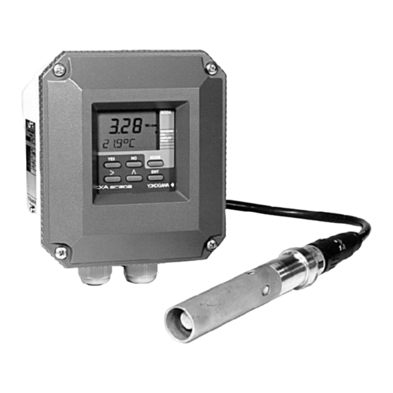
- Page 1 User’s Model SC202G(S) Conductivity and Resistivity Manual Transmitter YOKOGAWA IM 12D7B3-E-H 6th Edition...
-
Page 3: Table Of Contents
TABLE OF CONTENTS PREFACE CONFIGURATION CHECKLIST FOR SC202 1. INTRODUCTION AND GENERAL DESCRIPTION ..............1-1 1-1. Instrument check ........................1-1 1-2. Application..........................1-2 2. SC202 SPECIFICATIONS ......................2-1 2-1. General Specifications ......................2-1 2-2. Operating specifications......................2-2 2-3. Model and suffix codes......................2-3 2-4. Intrinsic safety - common specifications..................2-3 2-5. - Page 4 5-3. Service Codes ........................5-11 5-3-1. Parameter specific functions ..................5-12 5-3-2. Temperature compensation and measuring functions..........5-14 5-4. Temperature compensation ....................5-16 5-5. mA Output functions.......................5-18 5-6. User interface .........................5-20 5-7. Communication setup......................5-22 5-8. General ...........................5-22 5-9. Test and setup mode......................5-22 6. CALIBRATION ..........................6-1 6-1.
- Page 5 Do not use an abrasive or solvent in cleaning the instrument. Notice Contents of this manual are subject to change without notice. Yokogawa is not responsible for damage to the instrument, poor performance of the instrument or losses resulting from such, if the problems are caused by: Improper operation by the user.
- Page 6 CONFIGURATION CHECKLIST FOR SC202 Primary choices default alternatives reference on page menu Measurement Conductivity Resistivity 5.8- 5.9 SC 01 Range 0-1000 µS/cm max. 1999 mS°C "range" Temperature unit Celsius Fahrenheit 5.10- 5.11 SC 11 Sensor Cell constant 0.1 /cm any value between 0.08 and 50 5.8-5.9, 6.1- 6.3 SC 03 Sensor type 2-electrode...
-
Page 7: Introduction And General Description
This user’s manual contains the information needed to install, set up, operate and maintain the unit correctly. This manual also includes a basic troubleshooting guide to answer typical user questions. Yokogawa can not be responsible for the performance of the EXA analyzer if these instructions are not followed. 1-1. Instrument check Upon delivery, unpack the instrument carefully and inspect it to ensure that it was not damaged during ship- ment. -
Page 8: Application
For best results, read this manual in conjunction with the corresponding sensor user’s manual. Yokogawa designed and built the EXA to meet the CE regulatory standards. The unit meets or exceeds stringent requirements of EN 55082-2, EN55022 Class A without compromise, to assure the user of continued accurate performance in even the most demanding industrial installations. -
Page 9: Sc202 Specifications
Specifications 2-1 2. GENERAL SPECIFICATIONS 2-1. Specifications A. Input specifications : Two or four electrodes measurement - Matrix : : Conductivity function of concen- with square wave excitation. Cell con- tration and temperature. Choice out of stants from 0.008 to 50 cm-1 WU40 5 preprogrammed matrixes and a sensor cable up to 20m. -
Page 10: Operating Specifications
2-2 Specifications L. Input isolation : 1000 VDC G. Data protection : EEPROM for configuration and log- M. Shipping Details : Package size w x h x d book, and lithium battery for clock. 290 x 225 x 170 mm. H. -
Page 11: Connection Diagram For Power Supply
Specifications 2-3 2-3. Connection diagrams for power supply ATEX intrinsic safe and non-incendive diagrams for SC202S-A Intrinsically safe design EEX ib II 2 (1) G EEX ib [ia] IIC: T4 for ambient temperature < 55 ºC Certified safety barrier or power supply T6 for ambient temperature <... - Page 12 2-4 Specifications CSA intrinsic safe and non-incendive diagrams for SC202S-A Intrinsically safe design CSA Ex ia Class I, Div. 1, Group ABCD, T4 for ambient temp. < 55 ºC CSA certified T6 for ambient temp. < 40 ºC Safety barrier or power supply with Rint = 300 Ohm EXA SC202S analyzer (Hart compatible)
- Page 13 2-5 Specifications FM intrinsic safe diagrams for SC202S-A Intrinsically safe design FM Approved FM Class I. Div. 1, Group ABCD: T4 for ambient temperature < 55 ºC Safety barrier or power supply with R = 300 Ω T6 for ambient temperature < 40 ºC (HART compatible) EXA SC202S analyser Suitable values are:...
- Page 14 FM non-incendive diagrams for SC202S-N Intrinsically safe design FM Class I. Div. 2, Group ABCD: T4 for ambient temperature < 55 ºC T6 for ambient temperature < 40 ºC EXA SC202S analyser For electrical data: see text below Protective earth Load Resistance Unclassified Location...
-
Page 15: Installation And Wiring
Installation and wiring 3-1 3. INSTALLATION AND WIRING 3-1. Installation and dimensions 3-1-1. Installation site The EXA transmitter is weatherproof and can be installed inside or outside. It should, however, be installed as close as possible to the sensor to avoid long cable runs between sensor and transmitter. In any case, the cable length should not exceed 60 meters (200 feet). - Page 16 3-2 Installation and wiring wall mounting pipe mounting pipe mounting (vertical) (horizontal) (2.20) 2x ø6.5 (0.26) 4x ø10 (0.4) 92 (3.6) 115 (4.5) (2.75) 2" ND pipe OPTION /U: Universal pipe/wall mounting Figure 3-3. Wall and pipe mounting diagram Figure 3-4. Internal view of EXA wiring compartment IM 12D7B3-E-H...
-
Page 17: Preparation
Installation and wiring 3-3 3-2. Preparation Refer to figure 3-4. The power/output connections and the sensor connections should be made in accor- dance with the diagram on page 3-6. The terminals are of a plug in style for ease of mounting. To open the EXA 202 for wiring: 1. -
Page 18: Wiring Of Sensors
HOLD FAIL MODE MEASURE AUT.CAL YES NO MAN.CAL DISPLA Y TEMP HOLD MODE > YOKOGAWA OUTPUT/SUPPLY INPUT SENSORS 2,5 or 10 m DISTRIBUTOR 1 8 0 1 8 0 Safety Barrier SC202S only RECORDER Figure 3-6. System configuration 3-3. Wiring of sensors 3-3-1. -
Page 19: Wiring Of Power Supply
Installation and wiring 3-5 3-3-3. Installation in: Hazardous Area-Non-Incendive The SC202S-N may be installed in a Category 3/ Zone 2/ Div.2 area without the use of safety barriers. Maximum permissible supply voltage 31.5V 3-4. Wiring of power supply 3-4-1. General precautions Do not activate the power supply yet. -
Page 20: Sensor Wiring
Where a convenient installation is not possible using the standard cables between sensors and transmitter, a junction box and extension cable may be used. The Yokogawa BA10 junction box and the WF10 exten- sion cable should be used. These items are manufactured to a very high standard and are necessary to ensure that the specifications of the system can be met. -
Page 21: Other Sensor Systems
Where a convenient installation is not possible using the standard cables between sensors and transmitter, a junction box and extension cable may be used. The Yokogawa BA10 junction box and the WF10 exten- sion cable should be used. These items are manufactured to a very high standard and are necessary to ensure that the specifications of the system are not compromised. - Page 22 3-8 Installation and wiring TRANSMITTER / CONVERTER 15 Core 16 Screen White Co-axial cable Thermistor (Temperature sensor) 14 Overall Screen WF10 Cable 13 Core 17 Screen Secondary Coil Brown Co-axial Cable 11 Red Primary Coil 12 Blue Ground (Shield) Overall shield White Brown...
- Page 23 Installation and wiring 3-9 Extension cable may be purchased in bulk quantities, cut to length. Then it is necessary to terminate the cable as shown below. Termination procedure for WF10 cable. 1. Slide 3 cm of heat shrink tube (9 x 1.5) over the cable end to be terminated. 2.
- Page 24 IM 12D7B3-E-H...
-
Page 25: Operation; Display Functions And Setting
Installation and wiring 3-10 4. OPERATION; DISPLAY FUNCTIONS AND SETTING 4-1. Operator interface This section provides an overview of the operation of the EXA operator interface. The basic procedures for obtaining access to the three levels of operation are described briefly. For a step-by-step guide to data entry, refer to the relevant section of this user’s manual. -
Page 26: Explanation Of Operating Keys
4-1 Operation Fail flag Output hold flag Menu pointer flags Units MODE HOLD FAIL Main display Commissioning function menu Message display MEASURE OUTPUT DISPLAY SET HOLD YES NO HOLD TEMP. SERVICE Key prompt flags Commissioning MODE mode access key Selection keys YES : Accept setting : Change setting Measure/Maintenance... -
Page 27: Setting Passcodes
Operation 4-2 4-3. Setting passcodes 4-3-1. Passcode protection In Service Code 52, EXA users can set passcode protection for each one of the three operating levels, or for any one or two of the three levels. This procedure should be completed after the initial commissioning (setup) of the instrument. -
Page 28: Display Functions
Operation 4-3 4-5. Display functions Sequence for resistivity function is similar to this conductivity example. Display Functions (Sequence for resistivity function equals this conductivity example). Actual cell constant S / c m YES NO Reference temperature S / c m S / c m Software MODE... -
Page 29: Parameter Setting
Parameter setting 5-1 5. PARAMETER SETTING 5-1. Maintenance mode 5-1-1. Introduction Standard operation of the EXA instrument involves use of the Maintenance (or operating) mode to set up some of the parameters. Access to the maintenance mode is available via the six keys that can be pressed through the flexible win- dow in the instrument front cover. -
Page 30: Commissioning Mode
5-2 Parameter setting 5-2. Commissioning mode 5-2-1. Introduction In order to obtain peak performance from the EXA SC202, you must set it up for each custom application. Output ranges : mA output is set as default to 0-1 mS/cm or 0-19.99 M .cm. For enhanced resolution in more stable measuring processes, it may be desirable to select for example 5-10 µS/cm range. -
Page 31: Range
Parameter setting 5-3 5-2-2. Range MODE MEASURE OUTPUT DISPLAY SET HOLD HOLD TEMP. SERVICE MODE IM 12D7B3-E-H IM 12D7B3-E-H... -
Page 32: Hold
5-4 Parameter setting 5-2-3. HOLD MODE MEASURE OUTPUT DISPLAY SET HOLD HOLD TEMP. SERVICE HOLD HOLD HOLD YES NO Set HOLD "fixed value" HOLD HOLD YES NO YES NO HOLD active last measured value. IM 12D7B3-E-H IM 12D7B3-E-H... -
Page 33: Temperature Compensation
Parameter setting 5-5 5-2-4. Temperature compensation 1. Why temperature compensation? The conductivity of a solution is very dependent on temperature. Typically for every 1 °C change in temperature the solution conductivity will change by approximately 2 %. The effect of temperature varies from one solution to another and is determined by several factors like solution composition, concentration and temperature range. -
Page 34: Temperature Compensation Selection
5-6 Parameter setting 5-2-5. Temperature compensation selection MODE MEASURE OUTPUT DISPLAY SET HOLD HOLD TEMP. SERVICE After briefly displaying *WAIT* it will be possible to adjust the display reading to the correct value using > ENT keys. S / c m YES NO YES NO Briefly... -
Page 35: Service Code
Parameter setting 5-7 5-2-6. Service code The figure below shows a typical button sequence to change a setting within the service menu. The specific settings are listed in numerical sequence on the following pages. On the page facing the setting tables are concise explanations of the purpose of the service codes. -
Page 36: Service Codes
5-8 Parameter setting 5-3. Service Codes 5-3-1. Parameter specific functions Code 1 SC/RES Choose the required parameter, either conductivity or resistivity. If the parameter is changed the instrument will go into reset to load parameter specific default val- ues, followed by starting measurement. For all other service codes the instrument will return to commissioning mode after the service code setting is finished. - Page 37 Parameter setting 5-9 Code Display Function Function detail Default values Parameter specific functions *SC.RES Select main parameter Conductivity Cond. Resistivity *4-ELEC Select 2/4-EL system 2-Electrode measurement system 2-El. 4-Electrode measurement system *0.10xC Set cell constant Press NO to step through choice of 0.100 cm multiplying factors on the second display.
- Page 38 5-10 Parameter setting 5-3-2. Temperature measuring functions Code 10 T.SENS Selection of the temperature compensation sensor. The default selection is the Pt1000 Ohm sensor, which gives excellent precision with the two wire connec- tions used. The other options give the flexibility to use a very wide range of other conductivity/resistivity sensors.
- Page 39 Parameter setting 5-11 Code Display Function Function detail Default values Temperature measuring functions *T.SENS Temperature sensor Pt1000 Pt1000 Ni100 Pb36 Pt100 8k55 *T.UNIT Display in °C or °F °C °C °F *T.ADJ Calibrate temperature Adjust reading to allow for cable None resistance.
-
Page 40: Temperature Compensation
5-12 Parameter setting 5-4. Temperature compensation functions Code 20 T.R.°C Choose a temperature to which the measured conductivity (or resistivity) value must be compensated. Normally 25°C is used, therefore this temperature is cho- sen as default value. Limitations for this setting are: 0 to 100 °C. If T.UNIT in code 11 is set to °F, default value is 77°F and the limitations are 32 - 212°F. - Page 41 Parameter setting 5-13 Code Display Function Function detail Default values Temperature compensation functions *T.R.°C Set reference temp. Use >, ^, ENT keys to set value 25 °C *T.C.1 Set temp. coef. 1 Adjust compensation factor 2.1 % if set to TC in section 5-2-5. per °C Set value with >, ^, ENT keys *T.C.2...
-
Page 42: Ma Output Functions
5-14 Parameter setting 5-5. mA output functions Code 31 OUTP.F For the SC202 the output may be chosen as linear to input, or configured in a 21 point table to a particular linearization. Enable the table setup in code 31, and configure the table in code 35. - Page 43 Parameter setting 5-15 Code Display Function Function detail Default values mA Outputs Not used *OUTP.F mA output functions Linear Linear Table *BURN Burn function No burnout No Burn. Burnout downscale Burnout upscale Pulse burnout 33, 34 Not used *TABLE Output table for mA Linearization table for mA in 5% steps.
-
Page 44: User Interface
5-16 Service coded settings 5-6. User interface Code 50 *RET. When Auto return is enabled, the transmitter reverts to the measuring mode from anywhere in the configuration menus, when no button is pressed during the set time interval of 10 minutes. Code 52 *PASS Passcodes can be set on any or all of the access levels, to restrict access to the... - Page 45 Parameter setting 5-17 Code Display Function Function detail Default values User interface *RET Auto return Auto return to measuring mode Off Auto return to measuring mode On Not used *PASS Passcode Maintenance passcode Off 0.0.0 Off Note # = 0 - 9, where Maintenance passcode On Commissioning passcode Off 1=111, 2=333, 3=777 Commissioning passcode On...
-
Page 46: Communication Setup
5-18 Parameter setting 5-7. Communication setup Code 60 *COMM. The settings should be adjusted to suit the communicating device connected to the output. The communication can be set to HART or to PH201*B distributor (for Japanese market only). *ADDR. Select address 00 for point to point communication with 4-20mA transmission. Addresses 01 to 15 are used in multi-drop configuration (fixed 4mA output). - Page 47 Parameter setting 5-19 Code Display Function Function detail Default values Communication *COMM. Communication Set communication Set communication Set communication PH201*B On Communication write enable Write Communication write protect enable *ADDR. Network address Set address 00 to 15 *HOUR Clock setup Adjust to current date and time using *MINUT >, ^ and ENT keys...
- Page 48 IM 12D7B3-E-H...
-
Page 49: Calibration
6. CALIBRATION 6-1 When is calibration necessary? Calibration of conductivity/resistivity instruments is normally not required, since Yokogawa delivers a wide range of sensors, which are factory calibrated traceable to NIST standards. The cell constant values are normally indicated on the top of the sensor or on the integral cable. These values can be entered directly in service code 03 (section 5-3-1). -
Page 50: Calibration Procedure
6-2 Calibration 6-2. Calibration procedure Press the MODE key. MODE The legend CALIB appears, and the YES/NO key prompt flags flash. MEASURE DISPLAY HOLD MODE MODE Put the sensor in standard solution. Press YES. Set the value using the >, , ENT key. Select the flashing digit with the >... -
Page 51: Calibration With Hold Active
Calibration 6-3 6-3. Calibration with HOLD active Press the MODE key. MODE The legend CALIB appears, and the YES/NO key prompt flags flash. MEASURE DISPLAY HOLD MODE MODE HOLD HOLD HOLD HOLD Put the sensor in standard solution. Press YES. HOLD Set the value using the >, , ENT key. - Page 52 IM 12D7B3-E-H...
-
Page 53: Maintenance
The EXA instrument contains a lithium cell to support the clock function when the power is switched off. This cell needs to be replaced at 5 yearly intervals (or when discharged). Contact your nearest Yokogawa service centre for spare parts and instructions. - Page 54 IM 12D7B3-E-H...
-
Page 55: Troubleshooting
Troubleshooting 8-1 8. TROUBLESHOOTING The EXA SC202 is a microprocessor-based analyzer that performs continuous self-diagnostics to verify that it is working correctly. Error messages resulting from faults in the microprocessor systems itself are few. Incorrect programming by the user can be corrected according to the limits set in the following text. In addition, the EXA SC202 also checks the sensor to establish whether it is still functioning within specified limits. - Page 56 Reprogram Table values make no sense Wrong data programmed Reprogram Programmed values outside acceptable limits Incorrect configuration by user Reprogram All programmed data lost Fault in electronics Contact Yokogawa Very severe interference Checksum error Software problem Contact Yokogawa IM 12D7B3-E-H...
-
Page 57: Usp Water Purity Monitoring
USP 9-1 9. USP WATER PURITY MONITORING 9-1. What is USP ? USP stands for United States Pharmacopeia and it is responsible for issuing guidelines for the pharmaceuti- cal industry. Implementing these guidelines is highly recommended for companies wishing to market drugs in the US. -
Page 58: Setting Sc202 For Usp
9-2 USP 9-4. Setting up SC202 for USP First enable USP in service code 57. Change the setting from 0 (default) to 1 (enabled). This activates uncompensated conductivity in the display menu. The E13 feature is also enabled. For E13 the FAIL flag is triggered when the uncompensated conductivity exceeds the relevant value in the graph. -
Page 59: Spare Parts
Spare parts 10-1 10. SPARE PARTS Table 10-1. Itemized parts list Item No. Description Part no. Cover assembly including window, gasket and fixing screws K1542JZ Window K1542JN Internal works assembly (general purpose) K1544DJ Internal works assembly (intrinsically safe) K1544DK Digital (display) board K1544DB Analogue (input) board (general purpose) K1544SK... - Page 60 IM 12D7B3-E-H...
-
Page 61: Appendix
Appendix 11-1 11. APPENDIX 11-1. User setting for non-linear output table (code 31and 35) Output signal value Output 4-20 00.4 04.8 05.6 06.4 07.2 00.8 08.8 09.6 10.4 11.2 0.12 12.8 13.6 14.4 15.2 0.16 16.8 17.6 18.4 19.2 20.0 11-2. -
Page 62: Matrix Data Table
11-2 Appendix 11-3. Matrix data table (user selectable in code 22) Matrix, Solution Temp (°C) Data 1 Data 2 Data 3 Data 4 Data 5 HCL-p (cation) 0 ppb 4 ppb 10 ppb 20 ppb 100ppb selection 1 0.0116 µS 0.0228 µS 0.0472 µS 0.0911µS... -
Page 63: Sensor Selection
Appendix 11-3 11-4. Sensor Selection 11-4-1. General The inputs of the EXA transmitter are freely programmable for ease of installation. Standard 2-electrode type sensors with a cell constant of 0.100/cm and a Pt1000 temperature sensor, need no special programming. The EXA indicates a fault with a signal in the display field if there is a mismatch of sensors in the connec- tion. -
Page 64: User Setting Table
11-4 Appendix 11-6. User setting table FUNCTION SETTING DEFAULTS USER SETTINGS Parameter specific functions *SC.RES *4-Elec 2-Elec. *0.10xC 0.10xC Factor 1.000 *AIR *POL.C.K Temperature measuring functions *T.SENS Pt1000 *T.UNIT °C *T.ADJ None Temperature compensation functions *T.R.°C °C *T.C.1 %/°C *T.C.2 %/°C *MATRX None, see 5-2-5... - Page 65 Appendix 11-5 FUNCTION SETTING DEFAULTS USER SETTINGS User Interface *RET *PASS 0.0.0 all off *Err.01 hard fail *Err.05 hard fail *Err.06 hard fail *Err.07 hard fail *Err.08 hard fail *Err.13 soft fail *E5.LIM (0.004) *E6.LIM 1.000 µS (1.0) *0 % 100% 100.0 *DISP...
-
Page 66: Error Codes
Reprogram Table values make no sense Wrong data programmed Reprogram Programmed values outside acceptable limits Incorrect configuration by user Reprogram All programmed data lost Fault in electronics Contact Yokogawa Very severe interference Checksum error Software problem Contact Yokogawa IM 12D7B3-E-H... -
Page 67: Device Description (Dd) Menu Structure
11-8. Device Description (DD) menu structure The Device Description (DD) is available from Yokogawa or the HART foundation. An example is shown below of the ON LINE menu structure. This manual makes no attempt to explain the operation of the Hand Held communicator (HHC). -
Page 68: Field Change Order
11-8 Appendix 11-9. Field Change Order 11-9-1 Changes made by software release 1.1 • PH201 communication added for Japanese market 11-9-2 Changes made by software release 1.1 • E20 is cleared after the programmed data was recovered 11-9-3 Changes made by software release 2.1 •... -
Page 69: Test Certificate
Test Certificate 12-1 12.1 TEST CERTIFICATE Test EXA Series Certificate Model SC202 Inductive Conductivity Transmitter Introduction This inspection procedure applies to the model SC202 Conductivity transmitter. There is a serial num- ber, unique to the instrument, which is stored in non-volatile memory. Each time the transmitter is pow- ered up, the serial number is shown in the display. - Page 70 12-2 Test Certificate 4.3 Overall Accuracy Test This test can be performed by the end-user to check the overall accuracy of the instrument. The data specified on the Test certificate are results of the overall accuracy test performed during production and can be reproduced by performing similar tests with the following test equipment: 1.
- Page 71 Test Certificate 12-3 IM 12D7B3-E-H...
- Page 72 28028 MADRID GERMANY Via Yokogawa Ges.m.b.H.: Yokogawa Ges.m.b.H. 18-20 Rue Grange Dame Rose Tel. +34-91-724 20 80 Rota Yokogawa GmbH & Co. KG Czechia, Slovakia, Poland, Central East Europe Fax +34-91-355 31 40 Rheinstrasse 8 78140 VELIZY VILLACOUBLAY Croatia, Slovenia, Jugoslavia, Franzosengraben 1 Tel.
Need help?
Do you have a question about the SC202G(S) and is the answer not in the manual?
Questions and answers