
Related Manuals for YOKOGAWA YTA610


Summary of Contents for YOKOGAWA YTA610
- Page 1 User’s Manual YTA610 and YTA710 Temperature Transmitters (Hardware) IM 01C50G01-01EN IM 01C50G01-01EN 4th Edition...
-
Page 2: Table Of Contents
Hardware Error Burnout and Hardware Write Protect Switch ..... 3-1 Integral Indicator Display Function..............3-2 Local Parameter Setting ................... 3-3 3.4.1 Local Parameter Setting (LPS) Overview .......... 3-3 3.4.2 Parameters Configuration ..............3-6 4th Edition: Mar. 2018 (YK) IM 01C50G01-01EN All Rights Reserved, Copyright © 2016, Yokogawa Electric Corporation... - Page 3 Integral Indicator and Error Display ..............6-6 General Specifications ................7-1 7.1 Standard Specifications ................... 7-1 7.1.1 YTA710 ....................7-1 7.1.2 YTA610 ....................7-7 7.2 Model and Suffix Codes ................. 7-12 7.3 Optional Specifications (YTA610 and YTA710) ..........7-13 Dimensions (YTA610 and YTA710) ............... 7-24 Revision Information IM 01C50G01-01EN...
-
Page 4: Preface
These manuals can be downloaded from the • No maintenance should be performed on website of Yokogawa or purchased from the explosionproof type temperature transmitters Yokogawa representatives. while the equipment is energized. If Website address: http://www.yokogawa.com/fld/... -
Page 5: For Safe Use Of Product
(d) Modification or characters (upper/lower case) that differ slightly Yokogawa will not be liable for malfunctions or from the full-scale screen to an extent that does not damage resulting from any modification made hinder the understanding of functions or monitoring to this instrument by the customer. -
Page 6: Warranty
<1. Preface> ■ Warranty • The warranty period of the instrument is written on the estimate sheet that is included with your purchase. Any trouble arising during the warranty period shall be repaired free of charge. • Inquiries with regard to problems with the instrument shall be accepted by the sales outlet or our local dealer representative. -
Page 7: Atex Documentation
<1. Preface> ■ ATEX Documentation This procedure is only applicable to the countries in European Union. IM 01C50G01-01EN... -
Page 8: Control Of Pollution Caused By The Product
<1. Preface> ■ Control of Pollution Caused by the Product This is an explanation for the product based on “Control of Pollution caused by Electronic Information Products” in the People’s Republic of China. IM 01C50G01-01EN... -
Page 9: Notes On Handling
<2. Notes on Handling> Notes on Handling Storage The YTA temperature transmitter is fully factorytested upon shipment. When the YTA is When an extended storage period is expected, delivered, check the appearance for damage, observe the following precautions: and also check that the transmitter mounting 1. -
Page 10: Use Of A Transceiver
<2. Notes on Handling> 2.6.1 Insulation resistance test procedure (3) Impact and Vibration It is recommended that the instrument be installed Testing between the output terminal and in a location that is subject to a minimum amount of input terminal impact and vibration. -
Page 11: Withstand Voltage Test Procedure
<2. Notes on Handling> Testing between the input terminal and Testing between the output terminal and grounding terminal the grounding terminal 1. Lay transition wiring between terminals 1, 2, 1. Lay the transition wiring between the + terminal, 3, 4 and 5 of the terminal box, and connect the the - terminal and the check terminal of the insulation resistor (with the power turned OFF) -
Page 12: Installation Of Explosion Protected Type Transmitters
• Dielectric strength: 500 V a.c.r.m.s.,1 min 2.7.1 ATEX Certification (See specific conditions of use) Fieldbus type (1) Technical Data • YTA610 and YTA710 with /KU25 temperature a) ATEX intrinsically safe approval transmitter (Fieldbus type) is applicable for use in hazardous locations. Caution for ATEX intrinsically safe approval. - Page 13 Transmitter is made of aluminum alloy, if Note 1. Certificate information it is mounted in an area where the use of • YTA710 with /KF2, YTA610 and YTA710 with Category 1G equipment is required, it must /KU2 and /KU25 temperature transmitters are be installed such that, even in the event applicable for use in hazardous locations.
- Page 14 The instrument modification or parts replacement Note 5. Maintenance and Repair by other than authorized Representative of • The instrument modification or parts Yokogawa Electric Corporation is prohibited and replacement by other than authorized will void the certification. representative of Yokogawa Electric Corporation is prohibited and will void ATEX Flameproof Certification.
- Page 15 <2. Notes on Handling> (6) Name Plate Intrinsically safe approval and Flameproof and Dust ignition approval (Fieldbus type) YTA710 /KF2 Flameproof and Dust ignition proof type II 3 G Ex ic IIC T4 Gc -30 ≤ Ta ≤ 70°C IP66/IP67 FISCO field device - - - - - - - - - - - - - - - - - - - - - - - - - - Supply/Output:...
-
Page 16: Iecex Certification
Note 1. Certification information Lo=3.9mH 4 - 20mA type • Electrical parameters (Ex ic): • YTA610 and YTA710 with /SU2 temperature Supply/Output circuit: Terminals: +, - transmitter (4 - 20mA type) is applicable for use FISCO field device or in hazardous locations. - Page 17 • Electrostatic charge may cause an explosion Note 1. Certification information hazard. Avoid any actions that cause the • YTA710 with /SF2, YTA610 and YTA710 with generation of electrostatic charge, such as /SU2 and /SU25 temperature transmitters are rubbing with a dry cloth on coating face of applicable for use in hazardous locations.
-
Page 18: Fm Certification
2-10 <2. Notes on Handling> 2.7.3 FM Certification Fieldbus type • YTA610 and YTA710 with /FU15 temperature (1) Technical Data transmitter (Fieldbus type) is applicable for use in hazardous locations. a) FM (US) intrinsically safe approval/non- • Applicable standard: incendive approval... -
Page 19: Csa Certification
Caution for FM Explosionproof type Caution for FM (Canada) intrinsically safe approval/ Note 1. Certification information non-incendive approval. • YTA710 with /FF1, YTA610 and YTA710 with Note 1. Certification information /FU1 and /FU15 temperature transmitter are 4 - 20mA type applicable for use in hazardous locations. - Page 20 • When the enclosure of the Temperature Fieldbus type Transmitter is made of aluminum alloy, if it is • YTA610 and YTA710 with /CU15 temperature mounted in Zone 0, it must be installed such transmitter (Fieldbus type) is applicable for use that, even in the event of rare incidents, an in hazardous locations.
- Page 21 WARNING: A SEAL SHALL BE INSTALLED WITHIN 50 cm OF THE Note 1. Certification information ENCLOSURE. UN SCELLEMENT • YTA710 with /CF1, YTA610 and YTA710 with DOIT ÊTRE INSTALLÉ À MOINS /CU1 and /CU15 temperature transmitters are DE 50 cm DU BOÎTIER.
-
Page 22: Control Drawing
2-14 <2. Notes on Handling> 2.7.5 Control Drawing Control Drawing for ATEX and IECEx Ex ia Yokogawa Electric Corporation YTAxxx Model Control Drawing Title IIE029-A63 2017-08-18 Page Revision Date Control Drawing (ATEX, IECEx) Intrinsically Safe Installation for YTAxxx – J or – D (Ex ia) Hazardous Area... - Page 23 2-15 <2. Notes on Handling> Control Drawing for ATEX and IECEx Ex ia Yokogawa Electric Corporation YTAxxx Model Control Drawing Title IIE029-A63 2017-08-18 Page Revision Date Intrinsically Safe Installation for YTAxxx – F or – G (Ex ia) Hazardous Area Hazardous Area Non-Hazardous Area Terminator Terminator Associated Apparatus −...
- Page 24 2-16 <2. Notes on Handling> Control Drawing ATEX Ex ic Yokogawa Electric Corporation YTAxxx Model Control drawing Title IKE061-A07 2017-12-27 Page Revision Date Intrinsically Safe Installation for YTAxxx – J or – D (Ex ic) Hazardous Area Hazardous Area Non-Hazardous Area Temperature Transmitter Associated Apparatus...
- Page 25 2-17 <2. Notes on Handling> Control Drawing ATEX Ex ic Yokogawa Electric Corporation YTAxxx Model Control drawing Title IKE061-A07 2017-12-27 Page Revision Date Intrinsically Safe Installation for YTAxxx – F or – G (Ex ic) Hazardous Area Hazardous Area Non-Hazardous Area Terminator Terminator Associated Apparatus −...
- Page 26 2-18 <2. Notes on Handling> Control Drawing IECEx Ex ic Yokogawa Electric Corporation YTAxxx Model Control Drawing Title IIE029-A63 2017-08-18 Page Revision Date Control Drawing (IECEx) Intrinsically Safe Installation for YTAxxx – J or – D (Ex ic) Hazardous Area...
- Page 27 2-19 <2. Notes on Handling> Control Drawing IECEx Ex ic Yokogawa Electric Corporation YTAxxx Model Control Drawing Title IIE029-A63 2017-08-18 Page Revision Date Intrinsically Safe Installation for YTAxxx – F or – G (Ex ic) Hazardous Area Hazardous Area Non-Hazardous Area...
- Page 28 2-20 <2. Notes on Handling> Control Drawing for FM (US) intrinsically safe approval (4 - 20 mA type) Yokogawa Electric Corporation YTAxxx Model Control Drawing Title IIE029-A61 2017-08-18 Page Revision Date Control Drawing (US) Intrinsically Safe Installation for YTAxxx – J or – D...
- Page 29 2-21 <2. Notes on Handling> Control Drawing for FM (US) Division 2 installation (4 - 20 mA type) Yokogawa Electric Corporation YTAxxx Model Control Drawing Title IIE029-A61 2017-08-18 Page Revision Date Division 2 Installation for YTAxxx – J or – D...
- Page 30 2-22 <2. Notes on Handling> Control Drawing for FM (US) intrinsically safe approval (Fieldbus type) Yokogawa Electric Corporation YTAxxx Model Control Drawing Title IIE029-A61 2017-08-18 Page Revision Date Intrinsically Safe Installation for YTAxxx – F or – G Hazardous (Classified) Location...
- Page 31 2-23 <2. Notes on Handling> Control Drawing for FM (US) Division 2 installation (Fieldbus type) Yokogawa Electric Corporation YTAxxx Model Control Drawing Title IIE029-A61 2017-08-18 Page Revision Date Division 2 Installation for YTAxxx – F or – G Hazardous (Classified) Location...
- Page 32 2-24 <2. Notes on Handling> Control Drowing for FM (US) intrinsically safe approval/non-incendive approval (4 - 20 mA & Fieldbus type) Yokogawa Electric Corporation YTAxxx Model Control Drawing Title IIE029-A61 2017-08-18 Page Revision Date Specific Conditions of Use: Electrostatic charges on the non-metallic parts (excluding glass parts) or coated parts of –...
- Page 33 2-25 <2. Notes on Handling> Control Drawing for FM (Canada) intrinsically safe approval (4 - 20mA type) Yokogawa Electric Corporation YTAxxx Model Control Drawing Title IIE029-A62 2017-08-18 Page Revision Date Control Drawing (Canada) Intrinsically Safe Installation for YTAxxx – J or – D...
- Page 34 2-26 <2. Notes on Handling> Control Drawing for FM (Canada) Division 2 installation (4 - 20 mA type) Yokogawa Electric Corporation YTAxxx Model Control Drawing Title IIE029-A62 2017-08-18 Page Revision Date Division 2 Installation for YTAxxx – J or – D...
- Page 35 2-27 <2. Notes on Handling> Control Drawing for FM (Canada) intrinsically safe approval (Fieldbus type) Yokogawa Electric Corporation YTAxxx Model Control Drawing Title IIE029-A62 2017-08-18 Page Revision Date Intrinsically Safe Installation for YTAxxx – F or – G Hazardous Location...
- Page 36 2-28 <2. Notes on Handling> Control Drawing for FM (Canada) Division 2 installation (Fieldbus type) Yokogawa Electric Corporation YTAxxx Model Control Drawing Title IIE029-A62 2017-08-18 Page Revision Date Division 2 Installation for YTAxxx – F or – G Hazardous Location...
- Page 37 2-29 <2. Notes on Handling> Control Drawings for FM (Canada) intrinsically safe approval/non-incendive approval (4 - 20 mA & Fieldbus type) Yokogawa Electric Corporation YTAxxx Model Control Drawing Title IIE029-A62 2017-08-18 Page Revision Date Specific Condition of Use: Electrostatic charges on the non-metallic parts (excluding glass parts) or coated parts of –...
-
Page 38: Emc Conformity Standards
Please use this instrument in the industrial environment only. NOTE YOKOGAWA recommends customer to apply the Metal Conduit Wiring or to use the twisted pair Shield Cable for signal wiring to conform the requirement of EMC Regulation, when customer installs the YTA Transmitter to the plant. -
Page 39: Part Names And Functions
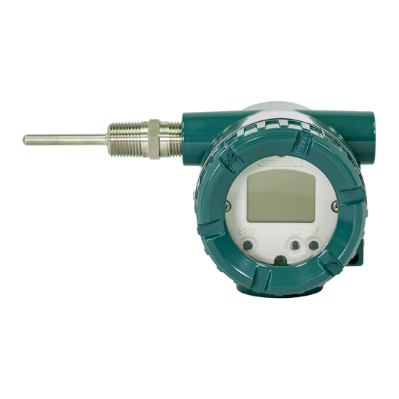
<3. Part Names and Functions> Part Names and Functions Part Names O-ring Burn out output direction Name plate setting switch upon hardware failure BOUT TEMP assembly MAIN assembly Terminal cover Stud bolt Indicator assembly Grounding terminal Amplifer cover Tag plate Lock screw (for ATEX and IECEx (HART/BRAIN) -
Page 40: Integral Indicator Display Function
<3. Part Names and Functions> Integral Indicator Display The temperature transmitter is equipped with a hardware error burnout function used to set the Function output direction upon hardware error, and a sensor burnout function that sets the direction of the output (1) Integral Indicator Display When Powering in the event of burnout of the temperature sensor. -
Page 41: Local Parameter Setting
<3. Part Names and Functions> Local Parameter Setting (2) Process Variable Display Process variables that can be displayed in YTA WARNING are shown in the Table 3.2. A cycle of up to four displays can be shown by assigning variables to the The local push button on the integral indicator parameters. - Page 42 <3. Part Names and Functions> Table 3.4 Parameters List (HART) Write Mode: RW=read/write, R=read only Item Indicator Display Write Mode Setting Type Remarks Tag number Character up to 8 characters Long tag number LNG.TAG Character up to 32 characters PV unit PV.UNIT Selection K, °C, °F, °R, mV, ohm, mA, %,...
- Page 43 <3. Part Names and Functions> Table 3.6 Parameters List (BRAIN) Write Mode: RW=read/write, R=read only Item Indicator Display Write Mode Setting Type Remarks Tag number Character up to 16 characters PV unit PV.UNIT Selection K, °C, °F, °R, mV, ohms, mA, %, NOUNIT PV damping time PV.DAMP...
-
Page 44: Parameters Configuration
<3. Part Names and Functions> 3.4.2 Parameters Configuration (3) Tag Number (TAG) Configuration TAG → Push SET button → Change the first (1) Activating Local Parameter Setting character by pushing ▲/▼ button → Push SET Push the ▲ or ▼ button on the integral indicator button to go to the second character →... - Page 45 <3. Part Names and Functions> (6) Other Parameters Configuration Parameter Indicator display Configuration Long tag number LNG.TAG Please refer to “Tag Number Configuration” for how to set. Sensor 1 type S1.TYPE Please refer to “PV Unit Configuration” for how to set. Sensor 1 wire S1.WIRE Please refer to “PV Unit Configuration”...
-
Page 46: Installation
<4. Installation> Installation • For details of choosing the installation location, IMPORTANT refer to the guidelines outlined in Section 2.4, “Choosing the installation location”. • When performing on-site pipe fitting work that • The mounting bracket shown in Figure 4.1 is involves welding, use care to prevent outflow used for the transmitter and is installed on 50A of the welding current into the transmitter. -
Page 47: Wiring
<5. Wiring> Wiring Notes on Wiring Loop Construction The YTA is a two-wire temperature transmitter that IMPORTANT uses the output power supply wiring and signal wiring alternately. • Apply a waterproofing sealant to the threads of the connection port. (It is recommended The transmission loop requires DC power. -
Page 48: Cable Selection
<5. Wiring> Cable Selection Cable and Terminal Connections 5.3.1 Input signal Cable Selection 5.4.1 Input Terminal Connections A dedicated cable is used for connection between the temperature sensor and the temperature NOTE transmitter. When a thermocouple is used as the temperature It is recommended that the terminals be sensor, a compensation wire must be used that it connected in the order of STEP 1 and STEP 2. -
Page 49: Output Terminal Connection
<5. Wiring> 5.4.2 Output Terminal Connection The temperature sensor is to be connected as shown in Figures 5.5. (1) Connection of output signal/power supply cable Connect the output signal cable (shared with the power supply cable) to the – terminal and the + terminal. -
Page 50: Wiring Cautions
<5. Wiring> Wiring Cautions (1) General-use Type Use metal conduit wiring or a waterproof gland (metal wiring conduit JIS F 8801) for cable wiring. • Apply nonhardening sealant to the threads of the wiring tap and a flexible fitting for secure waterproofing. -
Page 51: Maintenance
<6. Maintenance> Maintenance General 1. In accordance with the example wiring shown in Figure 6.1, connect each equipment and initiate Each component of this instrument is configured in warm up. Lay wiring on the input side according units to make maintenance easier. to the sensor to be used. -
Page 52: Disassembly And Assembly
<6. Maintenance> Disassembly and Assembly 2. For DC voltage input With a voltage generator, deliver input signals This section details the procedure for part corresponding to 0, 25, 75, or 100% of the input replacement or disassembly and assembly of span to the temperature transmitter. -
Page 53: Replacement Of Integral Indicator
<6. Maintenance> Mounting the Integral indicator Terminal cover Integral Indicator can be installed in the following three directions. TEMP assembly MAIN assembly Indicator assembly Amplifer cover Lock screw (for ATEX and IECEx flameproof type) Stud bolt F0602.ai Figure 6.2 Mounting and Removal of Integral Indicator Assembly 6.3.1 Replacement of Integral Indicator... -
Page 54: Troubleshooting
<6. Maintenance> Troubleshooting 6.4.2 Example of Troubleshooting Flow When the measured value is found abnormal, The following phenomena indicate that this follow the troubleshooting flowchart below. If the instrument may be out of operation. [Example] complex nature of the trouble means that the cause •... - Page 55 <6. Maintenance> Table 6.3 Problems, Causes and Countermeasures (HART and FF) Related Observed Related Parameter Possible Cause Countermeasure Parameter Problems (FF) (HART) Output fluctuates Span is too narrow. Check the range, and change PV LRV ─ greatly. the settings to make the span PV URV larger.
-
Page 56: Integral Indicator And Error Display
<6. Maintenance> Integral Indicator and Error Display For temperature transmitters equipped with an integral indicator, errors in the temperature sensor or the transmitter cause an integral indicator to call up the applicable error code. Table 6.5 lists the error codes for HART and BRAIN. - Page 57 <6. Maintenance> Alarm Indicator Cause Output operation during error Number Message AL.51 LRV HI LRV setting is above the sensor operating Continue to operate and output temperature range AL.52 URV LO URV setting is below the sensor operating Continue to operate and output temperature range AL.53 URV HI...
- Page 58 <6. Maintenance> Table 6.7 List of Error Codes (FF) Alarm Indicator Cause Number Message AL.00 CPU.ERR MAIN CPU failed AL.01 SENSOR Sensor non-volatile memory verifies alarm AL.02 TMP.MEM Non-volatile memory of the TEMP ASSY verifies alarm AL.03 AD.CONV Input circuit hardware failed AL.04 CAL.ERR MAIN ASSY memory failed...
- Page 59 <6. Maintenance> Alarm Indicator Cause Number Message AL.117 AI4 O/S The actual mode of the AI4 block is O/S. AL.118 SCHEDL Execution of AI1 is not scheduled. AL.119 SCHEDL Execution of AI2 is not scheduled. AL.120 SCHEDL Execution of AI2 is not scheduled. AL.121 SCHEDL Execution of AI1 is not scheduled.
-
Page 60: General Specifications
<7. General Specifications> General Specifications 7.1 Standard Specifications Functional Specifications Input signals 7.1.1 YTA710 Input number: single and dual input Input type is selectable: Thermocouples, 2-, 3-, Performance Specifications and 4-wire RTDs, ohms and DC millivolts. Accuracy See Table 7.1. HART and BRAIN communication type: Input signal source resistance (for T/C, mV) A/D accuracy/span + D/A accuracy 1 kΩ... - Page 61 <7. General Specifications> Output in Transmitter Failure (HART and BRAIN Analog input (AI) Type) Four independent AI blocks can be selected. Down-scale: –5%, 3.2 mA DC or less , sensor Digital input (DI) burnout –2.5%, 3.6 mA (Optional code C1) Four DI function blocks can be used as a Down-scale: –5%, 3.2 mA DC or less (Optional limit switch for those temperature.
- Page 62 <7. General Specifications> Safety Requirement Standards Normal Operating Condition EN61010-1, C22.2 No.61010-1 (Optional features or approval codes may affect • Altitude of installation site: limits.) Max. 2,000 m above sea level Ambient Temperature Limits • Installation category: I –40 to 85°C (–40 to 185°F) (Anticipated transient overvoltage 330 V) –30 to 80°C (–22 to 176°F) (with indicator •...
- Page 63 <7. General Specifications> Communication Requirements (BRAIN Type) Physical Specifications Communication Distance Enclosure Up to 2 km (1.25 miles) when using CEV Material & Coating polyethylene-insulated PVC-sheathed • Low copper cast aluminum alloy cables. Communication distance varies [for aluminum housing] depending on type of cable used. Urethane-cured polyester powder coating Load Capacitance Mint-green paint (Munsell 5.6BG 3.3/2.9...
- Page 64 <7. General Specifications> Table 7.1 Sensor type, measurement range, and accuracy. Measurement Range A/D Accuracy Minimum Sensor Type Standard Span Accuracy °C °F °C °F 100 to 300 212 to 572 ±3.0 ±5.4 300 to 1820 572 to 3308 ±0.75 ±1.35 -200 to -50 -328 to -58 ±0.35 ±0.63...
- Page 65 <7. General Specifications> Table 7.2 Temperature coefficient Sensor Type Temperature Coefficient Thermocouples E, J, K, N, T, L, U 0.08°C + 0.02% of abs.reading Thermocouples R, S, W3, C 0.25°C + 0.02% of abs.reading 100°C ≤ Reading < 300°C 1°C + 0.02% of abs.reading Thermocouple B 300°C ≤...
-
Page 66: Yta610
High (21.6 mA DC) or Low (3.6 mA DC), user Vibration Effect selectable. The YTA610 is tested to the following Output in Transmitter Failure (HART Type) specifications with no effect on performance per Down-scale: –5%, 3.2 mA DC or less , sensor IEC 60770-1 burnout –2.5%, 3.6 mA (Optional code C1) - Page 67 <7. General Specifications> Sensor-Diagnostics Software download function Sensor failure: Detect the disconnection of This function permits to update YTA software sensor. via a F fieldbus. OUNDATION Sensor line information: Measure the line Based on Fundation fieldbus specifications resistance. (FF883) Sensor drift: Detect the difference between Download class: Class 1 sensor1 and sensor2.
- Page 68 <7. General Specifications> Normal Operating Condition Physical Specifications (Optional features or approval codes may affect Enclosure limits.) Material & Coating Ambient Temperature Limits • Low copper cast aluminum alloy –40 to 85°C (–40 to 185°F) [for aluminum housing] –30 to 80°C (–22 to 176°F) (with indicator Urethane-cured polyester powder coating model) Mint-green paint (Munsell 5.6BG 3.3/2.9...
- Page 69 7-10 <7. General Specifications> Table 7.3 Sensor type, measurement range, and accuracy Measurement Range A/D Accuracy Minimum Sensor Type Standard Span Accuracy °C °F °C °F 100 to 300 212 to 572 ±3.0 ±5.4 300 to 1820 572 to 3308 ±0.77 ±1.39 -200 to -50...
- Page 70 7-11 <7. General Specifications> Table 7.4 Temperature coefficient Sensor Type Temperature Coefficient Thermocouples E, J, K, N, T, L, U 0.08°C + 0.02% of abs.reading Thermocouples R, S, W3, C 0.25°C + 0.02% of abs.reading 100°C ≤ Reading < 300°C 1°C + 0.02% of abs.reading Thermocouple B 300°C ≤...
-
Page 71: Model And Suffix Codes
<7. General Specifications> 7.2 Model and Suffix Codes Model Codes Description YTA610 · · · · · · · · · · · · · · · · Temperature Transmitter YTA710 Output · · · · · · · · · · · · ·... -
Page 72: Optional Specifications (Yta610 And Yta710)
The combination of X2 and P is not possible. Applicable for Electrical Connection code 4. (The thread of connection between YTA and CABLE GLAND is M20, and the thread of connection between CABLE GLAND and CABLE is G1/2.) Not applicable for YTA610. Not applicable for BRAIN type. *10: Not applicable for Fieldbus type. - Page 73 7-14 <7. General Specifications> Table 7.5 Temperature coefficient (R1) Input Range Sensor Type A/D Coefficient D/A Coefficient °C 100 to 300 ±(0.586°C - 0.1433% of reading) 300 to 1000 ±(0.187°C - 0.0103% of reading) 1000 to 1820 ±(0.038°C + 0.0046% of reading) -200 to 0 ±(0.007°C + 0.0158% of abs.reading) 0 to 1000 ±(0.007°C + 0.0065% of reading)
- Page 74 7-15 <7. General Specifications> [For Explosion Protected Type] Item Description Code ATEX [4-20mA & Fieldbus: Flameproof and dust ignition proof approval] Applicable Standard: EN 60079-0:2012+A11:2013, EN 60079-1:2007, EN 60079-31:2009 Certificate: KEMA 07ATEX0130 II 2 G Ex d IIC T6/T5 Gb, II 2 D Ex tb IIIC T70°C, T90°C Db Ambient Temperature for Gas Atmospheres: –40 to 75°C for T6, –40 to 80°C for T5 Ambient Temperature for Dust Atmospheres: –30 to 65°C for T70°C, –30 to 80°C for T90°C Enclosure: IP66/IP67...
- Page 75 7-16 <7. General Specifications> Item Description Code IECEx [4-20mA & Fieldbus: Flameproof and dust ignition proof approval] Applicable standard: IEC 60079-0:2011, IEC 60079-1:2007-04, IEC 60079-31:2008 Certificate: IECEx KEM 07.0044 Ex d IIC T6/T5 Gb, Ex tb IIIC T70°C / T90°C Db Ambient Temperature for Gas Atmospheres: –40 to 75°C (–40 to 167°F) for T6, –40 to 80°C (–40 to 176°F) for T5 Ambient Temperature for Dust Atmospheres: –30 to 65°C (–22 to 149°F) for T70°C,...
- Page 76 7-17 <7. General Specifications> Item Description Code FM (US) [4-20mA & Fieldbus: Explosionproof approval] Applicable standard: FM Class 3600: 2011, FM Class 3615: 2006, FM Class 3810: 2005, NEMA250: 2014 Class I, Division 1, Groups A, B, C and D.; Class II/III, Division 1, Groups E, F and G. "FACTORY SEALD, CONDUIT SEAL NOT REQUIRED."...
- Page 77 7-18 <7. General Specifications> Item Description Code [4-20mA & Fieldbus: Explosionproof approval] *3*7 Applicable standard: C22.2 No. 0-10, C22.2 No. 0.4-04, C22.2 No. 25-M1966, C22.2 No. 30-M1986, C22.2 No. 94-M1991, C22.2 No. 142-M1987, C22.2 No. 157-92, (Canada) *4*7 C22.2 No. 213-M1987, C22.2 No.61010-1-12, C22.2 No. 61010-2-030-12 Class I, Groups B, C and D, Class II, Groups E, F and G, Class III.
- Page 78 7-19 <7. General Specifications> Item Description Code Fieldbus: *3*7 [Intrinsically safe approval/non-incendive approval] Applicable standard: CAN/CSA-C22.2 No. 94.2-07, C22.2 No.213:1987, (Canada) *4*7 CAN /CSA-C22.2 No. 60079-0:11, CAN/CSA-C22.2 No. 60079-11:14, CAN/CSA-C22.2 No. 60529:05, CAN/CSA-C22.2 No. 61010-1-12, CAN/CSA-C22.2 No. 61010-2-030-12 Intrinsically safe for Class I, II, III, Division 1, Groups A, B, C, D, E, F, G T4 Ex ia IIC T4 Ga Non-incendive for Class I, II, Division 2, Groups A, B, C, D, F, G T4...
- Page 79 7-20 <7. General Specifications> Item Description Code NEPSI 4-20mA and Fieldbus: [Flameproof and Dust Ignition Proof Approval] Applicable Standard: GB3836.1-2010, GB3836.2-2010, GB12476.1-2013, GB12476.5-2013 Certificate No. GYJ16.1396X Ex d IIC T6/T5 Gb, Ex tD A21 IP66/IP67 T70°C/T90°C Ambient Temperature for Gas Atmospheres: –40 to 75°C for T6, –40 to 80°C for T5 Ambient Temperature for Dust Atmospheres: –30 to 65°C for T70°C, –30 to 80°C for T90°C Enclosure: IP66/IP67 Electrical Connection: 1/2 NPT female and M20 female...
- Page 80 7-21 <7. General Specifications> Item Description Code INMETRO [4-20mA & Fieldbus: Flameproof and dust ignition proof approval] Applicable Standard: ABNT NBR IEC 60079-0:2013 Versão Corrigida 2: 2016, ABNT NBR IEC60079-1:2016, ABNT NBR IEC 60079-31:2014 Certificate: DEKRA 16.0009 Ex db IIC T6/T5 Gb, Ex tb IIIC T70°C/ 90°C Db Ambient Temperature for Gas: –40 to +75°C for T6, –40 to +80°C for T5 Ambient Temperature for Dust: –30 to +65°C for T70°C, –30 to +80°C for T90°C Enclosure: IP66/IP67...
- Page 81 7-22 <7. General Specifications> Item Description Code KOSHA [4-20mA & Fieldbus: Flameproof and dust ignition proof approval] Applicable Standard: Notice of Ministry of Labor No. 2016-54, harmorized with IEC 60079-0:2011, IEC 60079-1:2014, IEC 60079-31:2013 Certificate: 17-AV4BO-0457 (Flameproof) 17-AV4BO-0458 (Dust Ignition Proof) Ex d IIC T6/ T5, Ex tD A21 IP66/IP67 T70°C/ T90°C Ambient Temperature for Gas Atmospheres: –40 to 75°C for T6, –40 to 80°C for T5 Ambient Temperature for Dust Atmospheres: –30 to 65°C for T70°C, –30 to 80°C for T90°C...
- Page 82 Applicable for Electrical Connection Code 2 and 4. Applicable for Electrical Connection Code 2. For Explosionproof approval. For Intrinsically safe approval/non-incendive approval. Not applicable for YTA610. GF1, /GS1 and /GS15 shall be combined with either /VE or /VR. Not applicable for BRAIN type. IM 01C50G01-01EN...
-
Page 83: Dimensions (Yta610 And Yta710)
7-24 <7. General Specifications> Dimensions (YTA610 and YTA710) Unit: mm (Approx. inch) 2-inch horizontal pipe mounting 65.4(2.57) 66.1(2.60) 111(4.37) Electrical Connection Electrical Connection 47.1 18.5 (Input signal) Terminal Cover (Output signal) (0.73) (1.85) With Indicator (Optional) Shrouding Bolt Ground Terminal... -
Page 84: Revision Information
Revised Item June 2016 — New publication. Oct. 2016 — Add YTA610. Incorporate manual change 16-028 and 16-045. Add document No. of GS 01C50H01-01EN. Add YTA610 to the table. Add ATEX Intrinsically safe approval. Revise the name plate. 2-6 & 2-7 Add name plate (intrinsically safe approval and Flameproof and Dust ignition approval). - Page 85 Edition Date Page Revised Item Mar. 2018 Revise ATEX intrinsically safe approval Add “Ex ic” of ATEX intrinsically safe approval 4-20mA type Add “Ex ic” of IECEx intrinsically safe approval Revise IECEx intrinsically safe approval 2-10 Revise FM (US) intrinsically safe approval/nonincendive 2-11 Revise FM (Canada) intrinsically safe approval/nonincendive approval 2-14 to 2-29...
Need help?
Do you have a question about the YTA610 and is the answer not in the manual?
Questions and answers