
Subscribe to Our Youtube Channel
Related Manuals for YOKOGAWA SC200


Summary of Contents for YOKOGAWA SC200
- Page 1 Model SC200 Instruction 2-wire Conductivity Manual or Resistivity transmitter IM 12D7B2-E-H 4th edition...
- Page 2 OUTPUT MANUALLY SET FAIL MENU POINTER HOLD FLAG TEMPERATURE FLAG FLAGS COMPENSATION MENU FOR FLAG MAINTENANCE FUNCTIONS see chapter 5 MEASURE VALUE TEMP.MAN HOLD FAIL MODE DISPLAY k Ω / c m µ S / c m m S / c m M Ω...
-
Page 3: Table Of Contents
CONTENTS 1. INTRODUCTION 5. MAINTENANCE..............20 1-1. Application..............1 5-1. Calibration........CAL......20 1-2. Required components for 5-2. Selecting a value to display ..DISPLAY ....22 conductivity measurement .........1 5-3. Use of the hold function ....HOLD....24 1-3. Identification...............2 6. TROUBLE SHOOTING ............26 2. TECHNICAL SPECIFICATIONS .........2 6-1. - Page 4 8. CLASSIFICATION .............36 8-1. Cenelec ..............36 8-2. FM ................37 9. CHANGE FROM CONDUCTIVITY TO RESISTIVITY MEASUREMENT .........38 9-1. How to change from conductivity to resistivity measurement............38 9-2. Resistivity measurement ..........38 9-3. Maintenance of the transmitter.........38 10. SOFTWARE VERSION 3.0 COMPARED TO VERSIONS 1 AND 2 ......39 10-1.
-
Page 5: Introduction
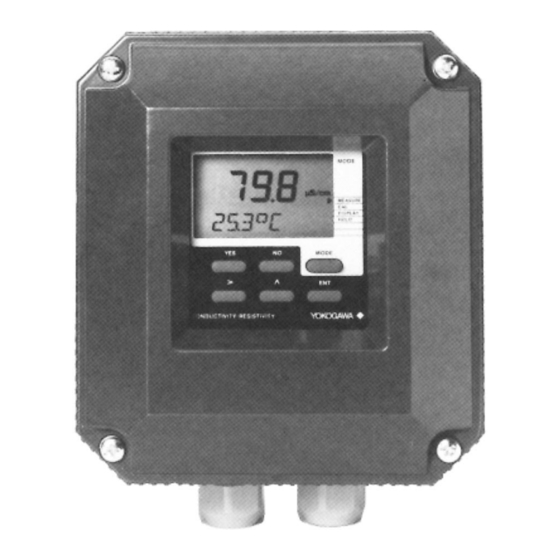
1. INTRODUCTION 1-1. Application 1-2. Required components for 1-3. Identification The EXA SC200 transmitter is a 2-wire con- conductivity measurement The instrument has an identification label, ductivity instrument intended to be used in A. a conductivity sensor ( also called con- which is fixed to the front plate. -
Page 6: Technical Specifications
2. SPECIFICATIONS G. Display method : Custom liquid crystal display. - Main display : 31/2digit, 12.5 mm high. 2-1. General specifications - Message display : 6 alphanumeric characters, 7 mm. - Special fields : Flags for status indication. A. Intrinsic safety (model SC200S only) : Units: µS/cm, mS/cm. -
Page 7: Functional Description
2-2. Functional description The keys are scanned continuously and the The instrument comes in 2 versions only: The EXA SC200 is a real time micro-control- actions are taken immediately. An extensive -A general purpose model. ler operated conductivity-analyzing system. system of checking values and parameters -An intrinsically safe model. -
Page 8: Installation And Wiring
162 (6.4) min. 203 (8) 154(6.06) 3-1-2. Mounting methods The EXA SC200 transmitter has universal 30 (1.18) mounting possibilities: - panel mounting using selftapping screws; - surface mounting on a plate (by bolts from the back);... - Page 9 Universal pipe/wall mounting 2x ø6.6 4x ø10 2" I.D. pipe 2" I.D. pipe Pipe mounting Pipe mounting Wall mounting (vertical) (horizontal) IM 12D7B2-E-H...
-
Page 10: Wiring Of Sensors
EXA SC200 by releasing the conductivity sensor is at a low voltage and nals of the EXA SC200 do not exceed the 4 captive screws. high impedance level. Thus care must be limits given in the certificate.This sets a limit... -
Page 11: Connecting Diagram For Sensors
3-2-5. Connecting diagram for sensors 2-Electrode system 4-Electrode system e.g. e.g. Use cable WU40/LH... Use cable WU40/LH... Max. recommended length 10 m Max. recommended length 10 m. Use Cells SC41 or SC42 Use Cells SC49 TEMPERATURE SENSOR TEMPERATURE SENSOR * Use of 4-electrode cell recommended Range selection Range selection... -
Page 12: Wiring Of Power Supply
§ 3-2-4. nals of the EXA SC200 do not exceed the Use the left-hand gland to insert the 2-wire limits given in the certificate of the safety cable to the transmitter. - Page 13 Wiring diagrams for power supply General purpose design Conductivity transmitter EXA SC200G Distributor NOTE: The outside earth terminal should be connected to site ground by a large area conductor (e.g. a flat earth strip) for best protection against interference. Dependance of load to supply voltage 1200 1000 1718...
- Page 14 Wiring diagrams for hazardous areas Intrinsically safe design (CELENEC standard EEX ib [ia] IIC T4) EEx ib Conductivity transmitter certified safety EXA SC200S barrier Distributor Elektronic current Limiting barrier Vmax: 31.5 V lmax : 35 Pmax: 0.66 W Zener barrier with resistor Vmax: 28 lmax : 93.3 mA...
-
Page 15: Commissioning
4. COMMISSIONING 4-1. Operations overview Routine Chapter Calibration MAINTENANCE Operation by keys DISPLAY Show or fix additional values through the closed cover HOLD Switching hold function on/off COMMISSIONING OUTPUT Adjusting the output range Operation by *-key when cover is removed SET HOLD Activating the hold function TEMPERATURE... -
Page 16: Output Range Adjustment
4-2. Output range adjustment 1. Access output 2. Adjust low span value 3. Adjust high span value µS/cm mS/cm OUTPUT O U T P U T O U T P U T SET HOLD S E T H O L D S E T H O L D TEMPERATURE T E M P . - Page 17 3. Example The display will always show the full range of A linear output range is programmed by The EXA SC200 has an output table which the instrument from 0-2000 mS/cm. entering two values: can be programmed to give any non-linear...
-
Page 18: Set Up Hold Function
4-3. Set up HOLD function 1. Access HOLD routine 2. Activate HOLD function 3. Adjust value to hold HOLD OUTPUT OUTPUT O U T P U T SET HOLD SET HOLD S E T H O L D TEMPERATURE TEMPERATURE T E M P . - Page 19 (caustic soda) has to be kept preventing all sorts of alarming situations to at 5% . The mixing process is controlled by occur. The EXA SC200 will keep the output frozen a conductivity transmitter and electro-mag- Two possibilities are generally used: during the following events: netic valves.
-
Page 20: Temperature Compensation
4-4.Temperature compensation 1. Access temperature 2. Select automatic NaCl 3 Select temperature coefficient compensation routine temperature compensation compensation TEMP. MAN mS/cm OUTPUT OUTPUT O U T P U T SET HOLD SET HOLD S E T H O L D TEMPERATURE TEMPERATURE T E M P . - Page 21 3. Measure the conductivity of the solution and the compensation factor is decreased with the SC200 and note the reading of A coefficient (a) is used to express the too. In these extreme regions the tempera- the display.
-
Page 22: Sensor Selection And Diagnostics
For conductivity values below 1 µS/cm the The EXA SC200 can be programmed to ac- only choice is a cell with cellconstant 0.01 cept any cell with a cell-constant between . From 1 µs/cm up to 10 mS/cm a cell- 0.01 and 50/cm. - Page 23 IM 12D7B2-E-H...
-
Page 24: Maintenance
5. MAINTENANCE 5-1. Calibration 1. Access calibration routine 2. Adjust value 3. End calibration MODE MODE MODE µS/cm µS/cm µS/cm M E A S U R E M E A S U R E M E A S U R E C A L C A L C A L... - Page 25 5-1. Calibration 1. When is calibration necessary? 2. How is calibration done? 3. Typical calibration solutions Calibration of conductivity instruments is not Calibration is carried out by measuring a The table below shows typical conductivity normally required since conductivity cells are solution which has a known conductivity values for solutions which may be made up manufactured within controlled tolerances...
-
Page 26: Selecting A Value To Display
5-2. Selecting a value to display 1. Access display routine 2. Read data 3. Reprogram data display MODE MODE MODE M E A S U R E M E A S U R E M E A S U R E C A L C A L C A L... - Page 27 5-2. Selecting a value to display 1. What is the display routine? 2. What can you read? 3. Example The second line in the display is intended to Temperature is an actual value. To check the value of the output signal be used to: Output is an actual value.
-
Page 28: Use Of The Hold Function
5-3. Use of HOLD function 1. Access hold 2. Switch hold on/off HOLD MODE MODE M E A S U R E M E A S U R E C A L C A L D I S P L A Y. D I S P L A Y. - Page 29 5-3. Use of HOLD function 1. What is HOLD? 2. How does it work? 3. Example Hold is a function which freezes the output From this level the HOLD function can only During the transfer of cleaning liquid into a signal temporarily, it is normally used during be switched ON or OFF.
-
Page 30: Trouble Shooting
6. TROUBLE SHOOTING 6-1. Introduction 6-2. Self diagnostics of the conductivity 6-3. Self diagnostics of the temperature The EXA SC200 microprocessor based cell sensor conductivity analyser continuously monitors During measurement the instrument adjusts The temperature sensor, which is normally the condition of all key components of the... -
Page 31: Error Messages And Explanation
Check programming of table descending or vice versa Programmed value not accepted Values not acceptable Reprogram with new values E20* Data lost Data, including initial setting, lost Call your YOKOGAWA service organisation * These errors will trigger the FAIL-status. IM 12D7B2-E-H... -
Page 32: Service Mode
7. SERVICE MODE Code Routine Chapter Temperature sensors and units Select sensor type 7-1. Introduction Select °C or °F Generally speaking their is no necessity to Reference temperature Adjust value adjust the settings of the service section All Output table or linear Select which to use parameters are pre-programmed to values Program output table... -
Page 33: Access To Service Settings
7-2. Access to service settings 1. Access service 2. Enter code to select 3. Adjust setting required function (see individual routines) OUTPUT O U T P U T O U T P U T SET HOLD S E T H O L D S E T H O L D TEMPERATURE T E M P . -
Page 34: Temperature Sensors And Units
Otherwise CODE 04 will have no effect. See Default value is Pt-1000 for Yokogawa sen- programmed temperature coefficient (e.g. the entry at the next CODE. -
Page 35: Output Table For Non-Linear Range
7-6. Output table for non-linear range Example of output tables ACCESS-CODE : 04 (see §7-2) mA-output range DISPLAY : 0% to 100% Output bi-lin log 2 log 3 hyp 2 hyp 3 0.10 1.00 0.10 Adjustment : A 21 step table can be 0.14 1.20 0.27... -
Page 36: Cell Constant Adjustment
Yokogawa produces several models with are pushed for 10 minutes. The 4-electrode principle is used for the cell-constants of 0.01, 0. 1, 1 and 10/cm. -
Page 37: Signalling Of Fail Condition
7-10. Temperature sensor adjustment 7-11. Signalling of fail condition 7-12. Temperature compensation ACCESS-CODE :08 (see § 7-2) ACCESS-CODE : 09 (see §7-2) coefficient adjustment DISPLAY :*T.ADJ DISPLAY : *BURN ACCESS-CODE : 10 (see § 7-2) DISPLAY : *T.C. Adjustment :Adjust the value of the indicated temperature Adjustment : X.X Adjustment... -
Page 38: Percent By Weight Indication On Second Display Line
Explanation: In case a conductivity measurement is used The instrument uses interpolation between The EXA SC200 normally checks the signal for concentration monitoring it can be con- the entered values. As the relation between from the cell to search for distortion typical... -
Page 39: Passcode Protection By Three Digit Code
0 = No passcode 5 = Passcode is 123 when entering from the measure mode. Yokogawa and thus erase all previously pro- 1 = Passcode is 111 6 = Passcode is 957 - For the Service level the passcode entry is grammed information. -
Page 40: Non Linear Ranges
Imax. out = 35 mA, P max. out = 1.1 W type : Yokogawa Bard 400 (BASEEFA Cert. Ex 84B2257x) ZONE 1 Any shunt zenerdiode safety barrier certified by BASEEFA or any EEC approeved certification body to [EEx ia] II C or [EEx ib] ii C where the ZONE 2 output current is limited by a resistor "R"... - Page 41 8-2. FM NON HAZARDOUS LOCATION FMRC-Approved Barrier 31.5 Vmax To be installed in accordance with ANSI/RP 12.6 and NEC requirements 4-20 mA Maximum safe area voltage should not exceed 250 V • HAZARDOUS LOCATION Class I, Division I, Groups ABCD Vmax = 31.5 V Imax...
-
Page 42: Change From Conductivity To Resistivity Measurement
9. CHANGE FROM CONDUCTIVITY TO RESISTIVITY MEASUREMENT 9-2.Resistivity measurement 9-3.Maintenance of the transmitter The EXA SC200 can be used for both con- As a resistivity measuring transmitter the Calibration of the resistivity transmitter is ductivity and resistivity measurement. As EXA SC200 has the same function as... -
Page 43: Software Version 3.0 Compared To Versions 1 And 2
10. SOFTWARE VERSION 3.0 COM- PARED TO VERSIONS 1* AND 2*. The new features are: 10-2.Matrix compensation In 1994 the software of EXA SC200 has un- 10-1. Cell constant ACCESS CODE : 13 dergone a major update as result of user... -
Page 44: Matrix Temperature-Compensation Range
Explanation: one in one specific access code (15 to 19). temperature range. In service codes 14 to 18 the SC200 trans- Adjust the conductivity value of the first solu- mitter can be fingerprinted to one particular tion at temperature T1 using keys > and ^. -
Page 45: Selection Between "Soft" Or "Hard" Fail Situations
10-5. Selection between ”soft” or ”hard” 10-6. Selection between yes or no E6 FAIL Situations Fail-message. ACCESS CODE : 20 Display : *ERR.01 Adjustment: Error 01 is skipped; next error is shown YES 0 = Soft alarm 1 = Hard alarm Pressing ENTER confirms the selec- tion Explanation:... -
Page 46: Matrix Examples
10-7 Matrix examples Temp. 0 ppb 4 ppb 10 ppb 20 ppb 100 ppb Cation 0,00975 0,152 0,31 0,62 1,23 Conductivity 0,0559 0,25 0,50 µS/cm 0,1752 0,385 0,70 1,35 2,70 0,4092 0,62 0,96 0,7681 0,98 Ammonia 0,00975 0,122 0,23 0,43 0,82 Conductivity 0,0559... - Page 47 IM 12D7B2-E-H...
- Page 48 The Netherlands Vicolo D. Pantaleoni, 4 SINGAPORE 1930 ZAVENTEM Tel. +31-33-4641 611 20161 MILANO Yokogawa Engineering Asia Pte. Ltd. Tel. +32-2-719 55 11 Fax +31-33-4641 610 Tel. +39-02-66 24 11 5 Bedok South Road Fax +32-2-725 34 99 E-mail: info@yokogawa.nl...
Need help?
Do you have a question about the SC200 and is the answer not in the manual?
Questions and answers