Table of Contents
Advertisement
Advertisement
Table of Contents

Related Manuals for Gefen Toolbox GTB-HDMI-3DTV


Summary of Contents for Gefen Toolbox GTB-HDMI-3DTV
- Page 1 Extender for HDMI 3DTV GTB-HDMI-3DTV User Manual www.gefentoolbox.com...
- Page 3 Notice Gefen, LLC reserves the right to make changes in the hardware, packaging and any accompanying documentation without prior written notice. GefenToolBox Extender for HDMI 3DTV is a trademark of Gefen, LLC HDMI, the HDMI logo, and High-Definition Multimedia Interface are trademarks or registered trademarks of HDMI Licensing in the United States and other countries.
-
Page 4: Table Of Contents
CONTENTS Introduction Operation Notes Features Sender Unit Layout Sender Unit Descriptions Receiver Unit Layout Receiver Unit Descriptions Connecting the Extender For HDMI 3DTV Wiring Diagram DIP Switch Configuration 11 Network Cable Wiring Diagram 12 Wall Mounting Instructions 13 Specifications 14 Warranty... -
Page 5: Introduction
IR “eye” can see the IR signals at the display location, or an external Gefen EXT-RMT-EXTIR IR Extender may be plugged into the Receiver and located near the display. Connect a Gefen EXT-2IREMIT IR Blaster to the Sender and locate the blasters near the source equipment. Only one CAT-5e cable connects the Sender and the Receiver units to each other. -
Page 6: Operation Notes
OPERATION NOTES READ THESE NOTES BEFORE INSTALLING OR OPERATING THE EXTENDER FOR HDMI 3DTV • CAT-5 or CAT-6 cables should not exceed 330 feet (100 meters). • Shielded (STP) CAT-5 or CAT-6 is recommended. However, unshielded (UTP) CAT-5 or CAT-6 is acceptable. NOTE: Shielded cable has an advantage by providing immunity to Electromagnetic Interference (EMI) from cell phones and A/C motors. -
Page 7: Features
FEATURES HDMI Features • 225 MHz (up to 12-bit YUV 4:4:4 @ 1080p60) • Deep Color • Dolby® TrueHD and DTS-HD® Master Audio™ • Lip-Sync • CEC Pass-Through Features • Extends resolutions up to 1080 Full HD and 4K (4096 x 2160 @ 24 Hz) up to 330 feet (100 meters) using one CAT-5e (or better) cable •... -
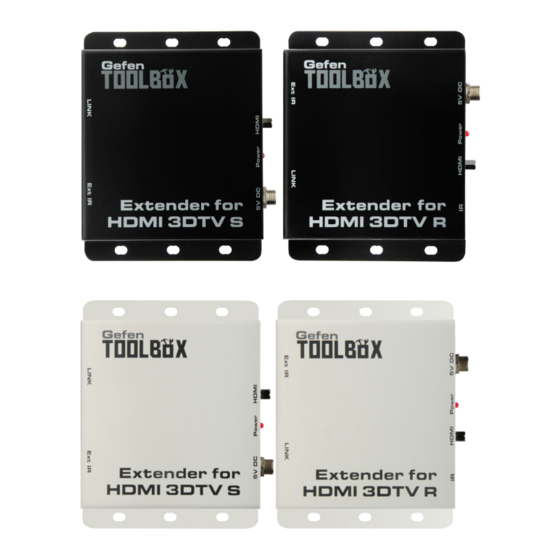
Page 8: Sender Unit Layout
SENDER UNIT LAYOUT Left Right... -
Page 9: Sender Unit Descriptions
SENDER UNIT DESCRIPTIONS Link Connects the Sender to the Receiver unit using CAT-5 cabling. Ext IR Connect an IR Blaster cable from this port to the Hi-Def source to control the source from the viewing location (IR Blaster not included). 5V DC Connect the included 5V DC locking power supply to this connector. -
Page 10: Receiver Unit Layout
RECEIVER UNIT LAYOUT Left Right... -
Page 11: Receiver Unit Descriptions
RECEIVER UNIT DESCRIPTIONS Ext IR Connect an IR extender (Gefen part no. RMT-IR-EXT) to this port. Link Connects the Receiver to the Sender unit using CAT-5e (or better) cabling. Receives signals from the 3D source IR remote control. The IR signals are sent back to the source device, when using an IR Blaster on the Sender. -
Page 12: Connecting The Extender For Hdmi 3Dtv
NOTE: If the source and display support 3D then the Extender for HDMI 3DTV will pass through the 3D signal. Wiring Diagram for the Extender for HDMI 3DTV CAT5 LINK CABLE (Up to 330 ft) HDMI CABLE Set-top Box Receiver IR Emitter IR Extender Sender HD Display GTB-HDMI-3DTV... -
Page 13: Dip Switch Configuration
DIP SWITCH CONFIGURATION DIP Switch Location On the bottom of the Extender for HDMI 3DTV Receiver unit there are four (4) DIP switches. The DIP switches allow advanced EDID management of the Extender for HDMI 3DTV which may be necessary when troubleshooting or using different brands of hardware. - Page 14 DIP SWITCH CONFIGURATION DIP 1 - EDID Mode ON (default) - External EDID Mode • DDC and HPD are passed through. Both the connection status and the full A/V capabilities of the display. The HPD status will also be detected by the source device.
-
Page 15: Network Cable Wiring Diagram
NETWORK CABLE WIRING DIAGRAM Gefen recommends the TIA/EIA-568-B wiring option. Please adhere to the table below when field terminating cable for use with Gefen products. Color Orange / White Orange Green / White Blue Blue / White Green Brown / White... -
Page 16: Wall Mounting Instructions
WALL MOUNTING INSTRUCTIONS The GefenToolbox Extender for HDMI 3DTV should be mounted vertically on a wall or inside / outside a cabinet with wood / drywall screws as shown in the diagram above. There should be an inch or two of clearance between the edges of the unit and any walls or vertical surfaces to allow for enough clearance for connection and disconnection of the HDMI cable. -
Page 17: Specifications
SPECIFICATIONS Maximum Pixel Clock................225 MHz Video Input Connector (Sender)......(1) HDMI Type-A , 19-pin, female Video Output Connector (Receiver).....(1) HDMI Type-A , 19-pin, female Link Connectors (Sender / Receiver).........(1) RJ-45, shielded IR Blaster Port (Sender)..........(1) 3.5mm mini-mono jack IR Extender Port (Receiver)..........(1) 3.5mm mini-stereo jack Power Indicators (Sender / Receiver)...........(1) LED, red Power Supply Connectors (Sender / Receiver)......(1) 5V DC, locking Power Consumption..............10W per unit (max.) -
Page 18: Warranty
If equipment fails because of such defects and Gefen is notified within two (2) years from the date of shipment, Gefen will, at its option, repair or replace the equipment, provided that the equipment has not been subjected to mechanical, electrical, or other abuse or modifications. - Page 20 Rev A8 20600 Nordhoff St., Chatsworth CA 91311 1-800-545-6900 818-772-9100 fax: 818-772-9120 www.gefentoolbox.com support@gefentoolbox.com This product uses UL or CE listed power supplies.
Need help?
Do you have a question about the Toolbox GTB-HDMI-3DTV and is the answer not in the manual?
Questions and answers