
Related Manuals for Gefen GTB-DVIKVM-ELR


Summary of Contents for Gefen GTB-DVIKVM-ELR
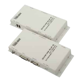
- Page 1 Gefen DVIKVM Extra Long Range Extender GTB-DVIKVM-ELR User Manual www.gefentoolbox.com...
- Page 2 Chatsworth, CA 91311 www.gefen.com support@gefen.com Notice Gefen LLC reserves the right to make changes in the hard ware, packaging and any accompanying doc u men ta tion without prior written notice. DVIKVM Extra Long Range Extender is a trademark of Gefen LLC ©...
-
Page 3: Table Of Contents
CONTENTS Introduction Operation Notes Features Sender Unit Layout Sender Unit Descriptions Receiver Unit Layout Receiver Unit Descriptions Connecting and Operating the DVIKVM Extra Long Range Extender DIP Switch Confi guration 12 Firmware Update 13 Network Cable Wiring Diagram 14 Mounting Plate Installation 15 Specifi... -
Page 4: Introduction
We invite you to explore our distinct product line. Please visit http://www.gefen.com for the latest offerings in High-Defi nition signal solutions or call us between the hours of 8:00 am and 5:00 pm Monday-Friday, Pacifi c Standard Time for assistance with your A/V needs. -
Page 5: Operation Notes
OPERATION NOTES PLEASE READ THESE NOTES BEFORE INSTALLING OR OPERATING THE DVIKVM EXTRA LONG RANGE EXTENDER • CAT-5 or CAT-6 cables should not exceed 330 feet (100 meters). • Shielded (STP) CAT-5 or CAT-6 is recommended. However, un-shielded (UTP) CAT-5 or CAT-6 is acceptable. NOTE: The shielded cable has an advantage by providing immunity to Electromagnetic Interference (EMI), cell phones and A/C motors. -
Page 6: Features
FEATURES Features • Supports DVI resolutions up to 1920x1200 @ 60 Hz or 1080p at 330 feet (100 meters) • Extends USB 2.0 up to 330 feet (100 meters) • Supports USB 2.0 480 Mbps • Backward-compatible with USB 1.1 devices •... -
Page 7: Sender Unit Layout
SENDER UNIT LAYOUT Right Side Left Side... -
Page 8: Sender Unit Descriptions
SENDER UNIT DESCRIPTIONS USB Link Connector Connects the USB signals from the Sender Unit to the Receiver Unit using CAT- 5e / CAT-6 cable. DVI / RS-232 Link Connector Connects the DVI and RS-232 signals from the Sender Unit to the Receiver Unit using CAT-5e / CAT-6 cable. -
Page 9: Receiver Unit Layout
RECEIVER UNIT LAYOUT Right Side Left Side... -
Page 10: Receiver Unit Descriptions
RECEIVER UNIT DESCRIPTIONS Remote Ethernet Port Connect a CAT-5 Cable from this jack to the remote device that needs an Ethernet LAN connection. Up to 100BaseT speeds are supported. DVI / RS-232 Link Connector Connects the DVI and RS-232 signals from the Receiver Unit to the Sender Unit using CAT-5e / CAT-6 cable. -
Page 11: Connecting And Operating The Dvikvm Extra Long Range Extender
Wiring Diagram for the DVIKVM Extra Long Range Extender Over One CAT5 CAT-5 LINK CABLE / ETHERNET (Up to 330 ft) RS-232 CABLE USB CABLE 100BASE-T Router or Ethernet switch DVI CABLE DVI Source Computer Receiver Receiver Sender Sender USB External HDD Monitor or Kiosk Touchscreen Display GTB-DVIKVM-ELR... -
Page 12: Dip Switch Confi Guration
DIP SWITCH CONFIGURATION Sender Unit The Gefen DVIKVM Extra Long Range Extender contains DIP switches on the bottom of the Sender Unit. Each DIP switch performs a different function. Two DIP switches located on the bottom of the Sender Unit. - Page 13 DIP SWITCH CONFIGURATION Receiver Unit The Gefen DVIKVM Extra Long Range Extender contains four (4) DIP switches on the bottom of the Receiver Unit. Each DIP switch performs a different function. Four DIP switches located on the bottom of the Receiver Unit.
- Page 14 DIP SWITCH CONFIGURATION DIP Switch 2 - Hot Plug Detect (Default = OFF)* • ON - HPD Pass-Through HPD follows upstream HPD towards the source. The HPD signal will refl ect the connection status between the display device and the source device. If the source or monitor is temporarily disconnected then reconnected, there will be a delay of 20 - 30 seconds before the content is restored to the monitor.
-
Page 15: Firmware Update
FIRMWARE UPDATE Updating the Firmware Connect an RS-232 cable from the computer to the Sender Unit. Set DIP switch 2 to the ON position. Connect the 5V DC locking power supply to the Sender Unit. Go to the directory where the fi rmware fi les are stored. Double-click the .BAT fi... -
Page 16: Network Cable Wiring Diagram
NETWORK CABLE WIRING DIAGRAM Gefen recommends the TIA/EIA-568-B wiring option. Please adhere to the table below when fi eld terminating cable for use with Gefen products. Color Orange / White Orange Green / White Blue Blue / White Green Brown / White... -
Page 17: Wall Mounting Instructions
WALL MOUNTING INSTRUCTIONS The GefenToolBox DVIKVM ELR Sender and Receiver may be mounted vertically in a wall or cabinet with wood/drywall screws as shown in the diagram above. There should be an inch or two of clearance between the edges of the unit and any walls or vertical surfaces to allow for enough clearance for insertion and retraction of cables at the DVI and RS-232 connectors. -
Page 18: Specifications
SPECIFICATIONS Maximum Pixel Clock................165 MHz Input Video Signal................1.2 Volts p-p Input DDC Signal................5 Volts p-p (TTL) DVI Connector (Sender / Receiver).........DVI-I 29-pin, female USB Connector (Sender).................(1) Type B USB Connector (Receiver)..............(2) Type A Ethernet Connector (Sender / Receiver)........RJ-45 (1 per unit) Link Connector (Sender / Receiver)........(4) RJ-45 (2 per unit) RS-232 Connector (Sender)...............DB-9, female RS-232 Connector (Receiver)..............DB-9, male... -
Page 19: Specifi Cations
Gefen warrants the equipment it manufactures to be free from defects in material and workmanship. If equipment fails because of such defects and Gefen is notifi ed within two (2) years from the date of shipment, Gefen will, at its option, repair or replace the equipment, provided that the equipment has not been subjected to mechanical, electrical, or other abuse or modifi... - Page 20 Rev A1 20600 Nordhoff St., Chatsworth CA 91311 1-800-545-6900 818-772-9100 fax: 818-772-9120 www.gefen.com support@gefen.com This product uses UL listed power supplies.
Need help?
Do you have a question about the GTB-DVIKVM-ELR and is the answer not in the manual?
Questions and answers