
Related Manuals for Gefen GTB-HDBT-POL


Summary of Contents for Gefen GTB-HDBT-POL
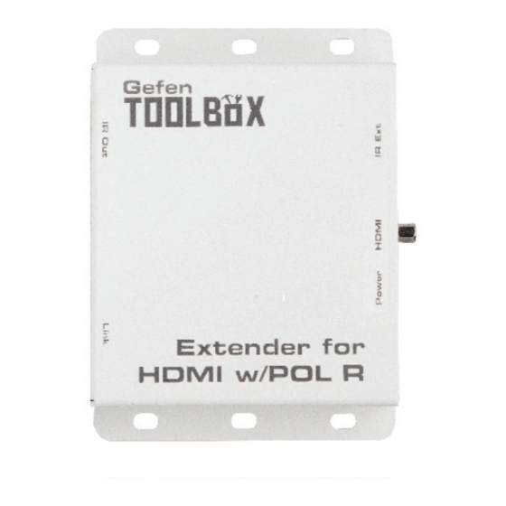
- Page 1 Extender for HDMI w/POL GTB-HDBT-POL GTB-HDBT-POL-BLK User Manual gefentoolbox.com gefentoolbox com...
- Page 3 Notice Gefen, LLC reserves the right to make changes in the hard ware, packaging, and any accompanying doc u men ta tion without prior written notice. Extender for HDMI w/POL is a trademark of Gefen, LLC HDMI, the HDMI logo, and High-Defi nition Multimedia Interface are trademarks or registered trademarks of HDMI Licensing in the United States and other countries.
-
Page 4: Table Of Contents
CONTENTS Introduction Operation Notes Features Sender Unit Layout Sender Unit Descriptions Receiver Unit Layout Receiver Unit Descriptions Connecting the Extender for HDMI w/POL Wiring Diagram Bi-Directional IR (Controlling the Source) Bi-Directional IR (Controlling the Display) 13 Network Cable Wiring Diagram 14 Wall Mounting Instructions 15 Specifications 16 Warranty... -
Page 5: Introduction
(Gefen part no. EXT-RMT-EXTIRC) to the Ext IR connector on the Receiver unit. Connect the IR emitter (Gefen part no. GTB-IREMIT) to the IR Out of the Sender unit and place the IR emitter over the IR sensor of the Hi-Def source. Point the IR remote at the IR Extender to control the Hi-Def source. -
Page 6: Operation Notes
NOTE: Shielded cable has an advantage by providing immunity to Electromagnetic Interference (EMI) from cell phones and A/C motors. • POL (Power Over Line) technology from Gefen sends power to the Receiver uni over the same CAT-5e/6 cable that is used for extending the HDMI signal. •... -
Page 7: Features
198ft (60 meters) over a single CAT-5e • Bi-Directional IR remote control of source device and the display • Gefen POL feature provides power to the Receiver unit over the CAT-6 • Uses HDBaseT® technology • Locking power connector •... -
Page 8: Sender Unit Layout
SENDER UNIT LAYOUT Front Back... -
Page 9: Sender Unit Descriptions
IR In Connect a mono or stereo 3.5mm-to-3.5mm cable from this jack to one of the IR Emitter jacks on the Gefen PACS or Gefen Mini PACS. IR Emitters or IR Extenders will not function if connected to this port. -
Page 10: Receiver Unit Layout
RECEIVER UNIT LAYOUT Front Back... -
Page 11: Receiver Unit Descriptions
RECEIVER UNIT DESCRIPTIONS IR Out Connect a single infrared IR emitter (Gefen part no. GTB-IREMIT) from this jack to the IR sensor window of the HDTV display. Link Connect a CAT-5e/CAT-6 cable from the Sender to the Receiver unit Power/HDCP Indicatior This LED will turn on once the included 24V DC power supply has been connected. -
Page 12: Connecting The Extender For Hdmi W/Pol
Connect the included 24V DC power supply to the Sender unit and plug the AC power cord into an available electrical outlet. Power to the Receiver unit is delivered from the Sender unit over the CAT-5e/CAT-6 cable using Gefen POL technology. -
Page 13: Bi-Directional Ir (Controlling The Source)
The source device can be controlled from the viewing location by connecting an IR Extender (Gefen part no. EXT-RMT-EXTIRC) to the Receiver unit. The display can be controlled from the source location by connecting a PACS / Mini PACS to the Sender unit. - Page 14 CONNECTING AND OPERATING THE EXTENDER FOR HDMI W/POL To control the source from the display location, point the included IR remote control at the IR Extender connected to the Receiver unit. The IR signals are transmitted from the Receiver to the Sender unit over the CAT-5e/CAT-6 cable. HDMI Cable e Receiver Unit IR Extender...
-
Page 15: Bi-Directional Ir (Controlling The Display)
For IR control of a display from the source location, connect a 3.5mm-to- 3.5mm mono or stereo cable from one of the IR Emitter jacks on an automation device, such as the Gefen PACS or Mini PACS, to the IR In jack on the Sender unit. - Page 16 CONNECTING AND OPERATING THE EXTENDER FOR HDMI W/POL To control the display from the source location, point the included IR remote control at the PACS or MIni PACS connected to the Sender unit. The IR signals are transmitted from the Sender to the Receiver unit over the CAT-5e/CAT-6a cable.
-
Page 17: Network Cable Wiring Diagram
NETWORK CABLE WIRING DIAGRAM Gefen recommends the TIA/EIA-568-B wiring option. Please adhere to the table below when fi eld terminating cable for use with Gefen products. Color Orange / White Orange Green / White Blue Blue / White Green Brown / White... -
Page 18: Wall Mounting Instructions
WALL MOUNTING INSTRUCTIONS The GefenToolbox Extender for HDMI w/POL should be mounted vertically on a wall or inside / outside a cabinet with wood / drywall screws as shown in the diagram above. There should be an inch or two of clearance between the edges of the unit and any walls or vertical surfaces to allow for enough clearance for connection and disconnection of the HDMI cable. -
Page 19: Specifications
SPECIFICATIONS Maximum Pixel Clock................225 MHz Video Input Connector (Sender)....(1) HDMI Type-A, 19-pin, female, locking Video Output Connector (Receiver)..(1) HDMI Type-A, 19-pin, female, locking Link Connectors (Sender / Receiver).........(1) RJ-45, shielded Power/HDCP Indicator LED: ..........Bi-color: Blue/Amber IR Extender Port (Receiver):..........3.5mm mini-stereo jack IR Out Port (Sender / Receiver):..........3.5mm mini-mono jack IR In port (Sender):............. -
Page 20: Warranty
Gefen warrants the equipment it manufactures to be free from defects in material and workmanship. If equipment fails because of such defects and Gefen is notifi ed within two (2) years from the date of shipment, Gefen will, at its option, repair or replace the equipment, provided that the equipment has not been subjected to mechanical, electrical, or other abuse or modifi... - Page 24 Rev A2 20600 Nordhoff St., Chatsworth CA 91311 1-800-545-6900 818-772-9100 fax: 818-772-9120 www.gefentv.com support@gefentv.com This product uses UL or CE listed power supplies.
Need help?
Do you have a question about the GTB-HDBT-POL and is the answer not in the manual?
Questions and answers