
Subscribe to Our Youtube Channel
Related Manuals for Rose electronics CrystalView DVI Plus


Summary of Contents for Rose electronics CrystalView DVI Plus
- Page 1 CrystalView DVI Plus™ Digital Fiber KVM USB Extender INSTALLATION OPERATIONS MANUAL CRK-1DFMT1SL / CRK-1DFMT2SL CRK-1DFMH1SL / CRK-1DFMH1SL 10707 Stancliff Road 800-333-9343 Houston, Texas 77099 www.rose.com...
- Page 3 LIMITED WARRANTY Rose Electronics warrants the CrystalView DVI Plus to be in good working order for one year from the date of purchase from Rose Electronics or an authorized dealer. Should this product fail to be in good working order at any time during this one-year warranty period, Rose Electronics will, at its option, repair or replace the Unit as set forth below.
- Page 4 FCC/CE STATEMENTS, EU DECLARATION OF CONFORMITY FEDERAL COMMUNICATIONS COMMISSION AND INDUSTRY CANADA RADIO-FREQUENCY INTERFERENCE STATEMENTS Models: CRK-1DFMT1SL CRK-1DFMT2SL CRK-1DFMT1DL CRK-1DFMH1SL CRK-1DFMH2SL CRK-1DFMH1DL This equipment generates, uses and can radiate radio frequency energy and if not installed and used properly, that is in strict accordance with the manufacturer’s instructions may cause interference to radio communication.
- Page 5 LASER SAFETY Laser Safety Precautions The CrystalView DVI Plus models can be operated in a non-restricted area and requires no laser warning labeling. The optical transceivers used in all models have a typical output power of approximately 5 mW. This corresponds to Hazard Class 1M as per EN 60825-2 (safety of optical fiber communications systems).
-
Page 6: Table Of Contents
Page # Disclaimer ......................1 System introduction ..................1 Compatibility ....................1 Features ......................2 Rose Electronics web site ................2 Package Contents ..................2 About this manual ..................2 Models ......................3 Installation – Singlelink / Single Video .............. 4 Installation –... -
Page 7: Disclaimer
DVI-D Duallink (6x1.6 Gbit/sec – Max resolution 2560 x 2048) Keyboard – All standard USB keyboards / USB keyboards with built-in hub Mouse – All standard 2, 3, and wheel mice USB Peripherals – Compatible USB 2.0 compliant devices CrystalView DVI Plus Installation and Operations Manual... -
Page 8: Features
Rose Electronics web site Visit our web site at www.rose.com for additional information on the CrystalView DVI Plus and other products designed for data center applications, classroom environments, and many other applications. Register your product for future updates at: www.rose.com/htm/online- registrationform.htm... -
Page 9: Models
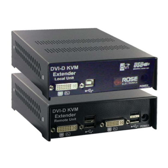
Front View Connectors 3- SC Type fiber (USB + KVM + Video) Local Rear View Connectors 2-DVI-D 2-USB Type B Power Remote Rear View Connectors 2-DVI-D 4-USB Type A Power Figure 1. Models CrystalView DVI Plus Installation and Operations Manual... -
Page 10: Installation - Singlelink / Single Video
6. Plug-in the two supplied power adapters to the local and remote units (5V / 2.4A to transmitter, 5V / 4A to receiver) 7. Power on the monitor, remote unit, local unit, and the computer CrystalView DVI Plus Installation and Operations Manual... -
Page 11: Installation - Singlelink / Dual Video
5. Attach your USB 2.0 compatible devices to the USB connectors on the remote unit. 6. Plug-in the two supplied power adapters to the local and remote units 7. Power on the monitors, remote unit, local unit, and the computer CrystalView DVI Plus Installation and Operations Manual... -
Page 12: Installation - Duallink / Single Video
5. Attach your USB 2.0 compatible devices to the USB connectors on the remote unit. 6. Plug-in the two supplied power adapters to the local and remote units 7. Power on the monitors, remote unit, local unit, and the computer CrystalView DVI Plus Installation and Operations Manual... -
Page 13: Diagnostic Leds
Monitor DDC is being transmitted from Remote Unit to Local Unit and stored there (only if video source switched off or not connected) Power Device not ready or no power applied (RED) Device ready CrystalView DVI Plus Installation and Operations Manual... -
Page 14: Ddc Information
LED at the Local Unit is blinking rapidly for approx. 1 second With some graphic cards you must reboot your CPU to make the graphic card accept the new DDC information from the Local Unit. CrystalView DVI Plus Installation and Operations Manual... -
Page 15: Troubleshooting
Check the DVI 1 and DVI2 LEDs. If they are off, check the video signal and graphic card settings. Keyboard or mouse do not operate Verify that the keyboard and mouse USB cables are connected to the correct USB ports on the receiver. CrystalView DVI Plus Installation and Operations Manual... -
Page 16: Service Information
Technical Support If you are experiencing problems, or need assistance in setting up, configuring or operating your CrystalView DVI Plus, consult the appropriate sections of this manual. If, however, you require additional information or assistance, please contact the Rose Electronics Technical Support... -
Page 17: Safety
SAFETY Safety The CrystalView DVI Plus KVM extender has been tested for conformance to safety regulations and requirements, and has been certified for international use. Like all electronic equipment, the CrystalView DVI Plus should be used with care. To protect yourself from possible injury and to minimize the risk of damage to the Unit, read and follow these safety instructions. - Page 18 Servicing There are no user-serviceable parts inside these products. Only service- trained personnel must perform any servicing, maintenance, or repair. The user may adjust only items mentioned in this manual. CrystalView DVI Plus Installation and Operations Manual...
-
Page 19: Appendix A - General Specifications
Approvals Audio Transmission Bi-directional stereo audio link Signal Level Line-level 5 volts peak-to-peak Impedance 47KΩ Mic. Powered or un-powered Speakers Powered Serial 19,200 baud / format independent / flow control Singlehead-RTS,CTS,DTR,DSR / Dualhead-Xon/Xoff CrystalView DVI Plus Installation and Operations Manual... -
Page 20: Appendix B - Part Numbers
Dual Link Models Part Number Description CRK-1DFMT1DL Single Video / DVI / USB 2.0 CRK-1DFMH1DL Single Video / DVI / USB HID /AUD = Audio option RM-VDP14/19 Rackmount bracket kit RM-BR3DV4 Rackmount shelf kit CrystalView DVI Plus Installation and Operations Manual... - Page 21 Appendix C – Rack mount Rack mounting the CrystalView DVI Plus uses the rackmount kit part number RM-BR3DV4. You can mount 1 to 3 units on a single shelf and mount the shelf in a standard 19” rack. The units can be orientated on the rack with either the front or rear panel facing to the front or rear of the shelf.
- Page 22 NOTES CrystalView DVI Plus Installation and Operations Manual...
- Page 24 10707 Stancliff Road Phone: (281) 933-7673 Houston, Texas 77099 WWW.ROSE.COM...
- Page 25 CrystalView DVI Plus™ Addendum Digital Fiber KVM USB Extender Serial / Audio Model addition 10707 Stancliff Road 800-333-9343 Houston, Texas 77099 www.rose.com...
- Page 26 Single video - SingleLink/DualLink USB HID serial audio model Front view – Transmitter / Receiver Connectors: Program Link C Mode switches Rear view – Transmitter Connectors: DVI in Serial / Audio Power Rear view – Receiver Connectors DVI out Serial / Audio Power Single video - SingleLink/DualLink USB 2.0 serial audio model Front view –...
- Page 27 Dual video – SingleLink USB HID serial audio model Front view – Transmitter / Receiver Connectors: Program Link B Link C Mode switches Rear view – Transmitter Connectors: 2- DVI in Serial / Audio Power Rear view – Receiver Connectors 2-DVI out Serial / Audio Power...
- Page 28 All Serial / Audio models install and connect in the same manor. Transmitter serial/audio installation Connect the Transmitter unit’s DB9F connector to the computer’s DB9M Com port using a standard serial cable (DB9MF). The Audio In connector on the Transmitter unit is a 3.5mm stereo audio port.
Need help?
Do you have a question about the CrystalView DVI Plus and is the answer not in the manual?
Questions and answers