Table of Contents
Advertisement
Owner's Manual and Instructions
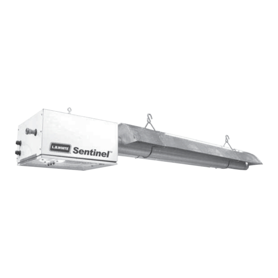
SENTINEL
Congratulations!
You have purchased the finest radiant tube heater available for the heating of
poultry confinement buildings.
Your new L.B. White radiant heater incorporates the benefits from the most
experienced manufacturer of heating products using state-of-the-art technology.
We, at L.B. White, thank you for your confidence in our products and welcome
any suggestions or comments you may have...call us toll free at (800) 345-7200.
ATTENTION ALL USERS
This heater has been tested and evaluated by C.S.A. International in
accordance with the requirements of standard ANSI Z83.20-2008 . CSA
2.34-2008 and is listed and approved as a direct gas-fired radiant tube
heater with intended use for the heating of poultry confinement buildings.
If you are considering using this product for any application other than its
intended use, then please contact your fuel gas supplier, or the
L.B. White Co., Inc.
®
Agricultural Building Radiant Tube Heaters
MODELS
AT 150
150,000
AT 125
125,000
AT 100
100,000
OUTPUT (Btuh)
FUEL
Propane Vapor
Withdrawal
Natural Gas
or
150-26736
Advertisement
Table of Contents

Related Manuals for L.B. White SENTINEL AT 150


Summary of Contents for L.B. White SENTINEL AT 150
- Page 1 Your new L.B. White radiant heater incorporates the benefits from the most experienced manufacturer of heating products using state-of-the-art technology. We, at L.B. White, thank you for your confidence in our products and welcome any suggestions or comments you may have...call us toll free at (800) 345-7200.
- Page 2 Save this Owner’s Manual for future use and reference. ■ Owner’s Manuals and replacement labels are available at no charge. For assistance, contact L.B. White at 800-345-7200. WARNING ■ Proper gas supply pressure must be provided to the inlet of the heater.
-
Page 3: Table Of Contents
When calling for technical service assistance, or for other specific information, always have the model number and Contact your local L. B. White distributor or the L.B. White serial number available. Co., Inc. for assistance, or if you have any questions about the use of the heater or its application. -
Page 4: Heater Specifications
Tube Heater Specifications Models SPECIFICATIONS AT100 AT125 AT150 Available Tube Lengths (ft.) Net Weight (lbs.) Shipping Weight (lbs.) Maximum Input per Hour (BTUH) 100,000 125,000 150,000 Minimum Input per Hour (BTUH) 65,000 75,000 90,000 (Two Stage Gas Control) L.P. GAS (lbs.) 4.63 5.79 7.09... - Page 5 FIG. 1 SAFE CLEARANCES FROM COMBUSTIBLES 6 FT 6 FT 1 FT 6 IN 6 FT 6 FT 6 FT 6 FT FIG. 2 TEMPERATURE SENSOR LOCATION HEATER SENSOR LOCATED DIRECTLY ABOVE INSIDE WATER LINE AND OR IN PROXIMITY SENSOR 12-18 IN.
-
Page 6: Safety Precautions
Safety Precautions WARNING Asphyxiation Hazard ■ Do not use this radiant heater for heating human living L.B. White Company to determine combustion air quarters. ventilation requirements of the heater. ■ ■ Do not use in unventilated areas. Lack of proper ventilation air will lead to carbon monoxide poisoning in humans leading to serious ■... - Page 7 2. All installations and applications of L.B. White heaters 11. Always turn off the gas supply to the heater when not must meet all relevant local, state and national in use.
-
Page 8: Installation Instructions General
Installation Instructions GENERAL 1. Read all safety precautions and follow L.B. White c. locations where wind and/or the recommendations when installing this heater. If elements can create a negative during the installation of the heater, you suspect that pressure. a part is damaged or defective, call a qualified service agency for repair or replacement. - Page 9 Consult your fuel gas Regulator installed inside should be vented supplier, or the L.B. White Co., Inc. for proper line outside. sizing and installation. Local state and national codes apply to regulator installation.
-
Page 10: Initial Setup
INITIAL SETUP 1. Plan the installation. Determine location for the FIG. 5 heater to optimize its heat pattern, keeping in mind cooler regions in the house (end walls, and curtains) JOIST and clearances to combustibles. OPEN EYE HOOKS IN LINE WITH 2. -
Page 11: Hanging The Tubes
HANGING THE TUBES Refer to Fig. 7 and the following instructions: 3. Slide on hangers and connect to chains. 1. Slide a tube clamp over the non-swaged end of 10 ft. 4. Connect and hang remaining tubes. F F ollow the aluminized tube. -
Page 12: Installing Reflectors & Supports
INSTALLING REFLECTORS & SUPPORTS Refer to Fig. 8 for the following instructions: 4. Attach remaining end cap to last reflector with U-clips. 1. Attach end cap to non-notched end of a reflector. Use 5. Install a support at end of reflector nearest burner 4 U-clips. -
Page 13: Air Turbulation Strips & Vent Hood
AIR TURBULATION STRIPS & VENT HOOD Assemble the strips and insert into last tube. Edge of strip FIG. 10 is flush with end of tube. See Fig. 9. Refer to Fig.10 for installation of vent hood. FIG. 9 TUBE VENT HOOD PUSH VENT HOOD FIRMLY ONTO END OF PUSH FIRMLY ONTO END TUBE LAST TUBE, OUTLET DOWN. -
Page 14: Heater Controls
HEATER CONTROLS Refer to the heater’s burner box hinged access panel, or Building Controller Connections (See Fig.15) refer to Start-up instructions in this manual to determine if -- Remove wire nut from yellow and orange wires. your heater has a single or two stage gas control. -- Connect controller contacts as shown. -
Page 15: Start-Up Instructions
Start-Up Instructions Follow steps 1 - 6 on initial start-up after heater installation. FIG. 19 For normal start-up, simply turn thermostat above room temperature. The heater will start. 1. Open all manual fuel supply valves and check for gas leaks using approved leak detectors. The gas control valve has a manual shut-off feature incorporated into the valve assembly. -
Page 16: Cleaning Instructions
Cleaning Instructions WARNING Fire, Burn, and Explosion Hazard ■ This heater contains electrical and mechanical components in the gas management, safety and airflow systems. ■ Such components may become inoperative or fail due to dust, dirt, wear, aging, or the corrosive atmosphere of an animal confinement building. -
Page 17: Maintenance Instructions
Maintenance Instructions 1. Have your gas supplier check all gas piping annually 6. If any warning or instruction labels, dataplates, etc. for leaks or restrictions in gas lines. Also, at this time become lost or hard to read, replace them have your gas supplier clean out the sediment trap on immediately. -
Page 18: Igniter
IGNITER The tip of the igniter is exposed to a harsh environment B. MAINTENANCE consisting of high temperatures and combustion products. Periodic servicing is required. Remove igniter from burner box. Ensure the gap is 1/8 in. See Fig. 22. A. REPLACEMENT Clean the electrode and ground rod using emery Remove igniter mounting screws. -
Page 19: Burner Orifice
BURNER ORIFICE 1. Remove the igniter FIG. 25 2. Remove the clear flexible tube from the pressure switch. Fig.24. . 3. Remove the four nuts from the burner mounting studs and remove burner . See Fig.24. ORIFICE FIG. 24 MANIFOLD TUBE 5. -
Page 20: Air Differential Pressure Switch, Tubing & Pressure Orifice
AIR DIFFERENTIAL PRESSURE SWITCH, TUBING & PRESSURE ORIFICES For proper heater operation: Servicing the differential air pressure switch: ■ ■ The copper pressure tube at the burner vane must The differential pressure switch is non- adjustable. If be straight. See Fig.31. the switch does not make the circuit after inspection of tubes and orifices, it must be replaced. -
Page 21: Gas Pressure Checks
Description Gas pressure gauges capable of reading up to 35 in. W.C. (may also be ordered from L.B. White, part number 00764) 1/2 in. x 3 in. nipple 1/2 in. tee 6. If connector is occupied by thermostat wiring, remove Bushing, 1/2 in.x 1/8 in. - Page 22 4. If the inlet pressure is correct but the burner manifold Single Stage Gas Controls pressure does not agree with that specified on the Set the thermostat to its highest setting. The single dataplate, then the pressure regulator internal to the amber light on the burner box panel will come on, and gas control requires adjustment.
-
Page 23: Troubleshooting Information
Troubleshooting Information Components should be replaced only after each step has READ THIS ENTIRE SECTION BEFORE BEGINNING TO TROUBLESHOOT PROBLEMS. been completed and replacement is suggested in the flow chart. Refer to the Servicing sections as necessary to obtain information on disassembly and replacement WARNING procedures of the component once the problem is identified ■... -
Page 27: Electrical Connection And Ladder Diagrams
Electrical Connection and Ladder Diagram SINGLE STAGE THERMOSTAT & GAS CONTROL... - Page 28 TWO STAGE THERMOSTAT & GAS CONTROL...
-
Page 29: Heater Component Function
Heater Component Function Burner Gas Hose Cast iron component used to channel gas and provide an Flexible connector used to convey gas from supply line in area at which the fuel may ignite. building to heater. Burner Orifice Igniter Brass metering device used to feed gas to burner at a Ignition device used on automatic direct spark ignition specific rate. -
Page 30: Parts Identification
Parts Identification PARTS SCHEMATIC... -
Page 31: Parts List
PARTS LIST AT125 AT150 AT100 Item Description 24737 ------------------------------ ------------------------------ Air Turbulation Strip 24859 ------------------------------ ------------------------------ Vent Hood 24587 ------------------------------ ------------------------------ Tube, Uncoated, 4 in. x 10 ft. 24586 ------------------------------ ------------------------------ Tube, Aluminized, 4 in. x 10 ft. ------------------------------ 24589 ------------------------------ Clamp 26804... -
Page 32: Warranty Policy
12 months from date of shipment from L B. White. the end user, any component is found to be defective, L.B. White Co., Inc. will at its option, repair or replace the defective part or heater, with a new part or heater, F.O.B., Onalaska, Wisconsin.
Need help?
Do you have a question about the SENTINEL AT 150 and is the answer not in the manual?
Questions and answers