Takagi T-M1 Installation Manual And Owner's Manual
Instantaneous water heater
Hide thumbs
Also See for T-M1:
- Installation and operating instructions manual (39 pages) ,
- Installation and operating instructions manual (39 pages) ,
- Installation and operation instruction manual (38 pages)
Table of Contents
Advertisement
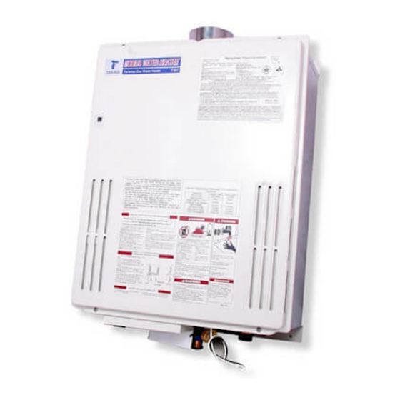
Mobius Water Heater™
Model T-M1.
Suitable for potable water heating and space heating
FEATURING
•
ENDLESS HOT WATER
•
ON DEMAND
•
COMPACT, SPACE SAVING
•
ENERGY CONSERVING
•
COMPUTER CONTROLS
•
COMPUTERIZED SAFETY
•
NO PILOT LIGHT
T-M1
Instantaneous Water Heater
Installation Manual and Owner's Guide
WARNING
This product must be installed and
serviced by a licensed plumber, a licensed
gas fitter, or a professional service
technician and/or in accordance with all
local code. Improper installation and/or
operation, or installation by an unqualified
person, will void the warranty.
WARNING
Operation of this unit creates carbon
monoxide gas and flue gases which can
cause serious injury or death. In addition,
if the information in this manual is not
followed exactly, a fire or explosion may
result causing property damage, personal
injury or death.
Takagi Industrial Co. USA Inc.
5 Whatney
Irvine, CA 92618
Toll Free (888) 882-5244 USA
Toll Free (877) 877-4953 CANADA
www.Takagi.com
Advertisement
Table of Contents

Related Manuals for Takagi T-M1


Summary of Contents for Takagi T-M1
- Page 1 Model T-M1. injury or death. Suitable for potable water heating and space heating FEATURING • Takagi Industrial Co. USA Inc. ENDLESS HOT WATER • ON DEMAND 5 Whatney • COMPACT, SPACE SAVING Irvine, CA 92618 •...
-
Page 2: Table Of Contents
Gas). For elevations above 6000ft or for Parts list …………31-32 specific instructions on how to lower the manifold pressure, please call the Takagi Output temperature Chart …………..33 office Manufacturer reserves the right to discontinue, or change at any time, specifications or designs without notice and without incurring obligations. -
Page 3: Introduction
Mobius T-M1 Water for the installation, operation, and maintenance Heater. Installation and service must be of the Model T-M1 water heater. This unit performed by a qualified installer (for includes a fan enabling sidewall (power) example, a licensed plumber or gas fitter) venting and an advanced electronic ignition system. - Page 4 Refer to the section on Water Heater is simple. Once you open a hot Winterizing and the Freeze Prevention water tap, water flows through the T-M1 Water Device for more information. The Warranty heater. Once a minimum of 0.75 GPM is...
-
Page 5: Installation
No. TK-TV06. damage caused to the unit due to installation contaminated When installed outdoors, the T-M1 water environment that has not be converted. heater shall be wall mounted only. Locate the 5. Particles from these objects may clog... -
Page 6: Indoor Installation
INDOOR INSTALLATION input of the total input rating of water heater in the enclosed area. These openings should When installed indoors, the T-M1 water heater never be less than 100 sq. in. shall be located in an area to maintain the... -
Page 7: Venting Instructions
Mechanical fan or Make up air device. other Category III approved, non-combustible, The T-M1 water heater is equipped with a corrosion-resistant material. The following are combustible air sensor that will shut off the unit UL listed manufacturers: ProTech Systems Inc. - Page 8 General rules for venting the T-M1 water Vent Termination heater are: A sidewall vent terminator must be used when the water heater is vented through a sidewall. 1. Place the water heater as close as possible Takagi recommends the use of its part No.TK- to the vent terminator;...
- Page 9 Canada U.S.A Direct vent and Direct vent Other than Direct Vent other than Direct Vent Clearance above grade, veranda, porch, 1 foot 1 foot 1 foot deck, or balcony. 4 feet from below or Clearance to window or door that may be 3 feet 1 foot side opening.
-
Page 10: Gas Supply/Gas Pipe Sizing
Until testing of the main gas line supply pressure is completed, ensure the gas line to the T-M1 is FOR YOUR SAFETY, READ disconnected to avoid any damage to the water heater. -
Page 11: Water Connection
1. Turn off the power supply to the T-M1 to replace any damaged parts. Water Heater. 2. Close the manual gas shut off valve located on the gas supply line. -
Page 12: Electrical Connection
5. Open the manual gas shut-off valve located on the gas supply line. The heater must be electrically grounded. Do 6. Turn on the power supply to the T-M1 not attach the ground wire to either the gas or Water Heater. -
Page 13: Initial Operation
Energy method of testing water heater output, on the water supply line. the T-M1 is rated for 300 gallons per hour 3. Open a hot water tap to verify that water is (GPH), or 5.0 gallons per minute (GPM), when flowing to that tap. -
Page 14: Temperature Setting
Hot Water Output Temperature Setting: With the MOBIUS T-M1 Water Heater, the output hot water temperature can be adjusted either manually from the main computer board’s dipswitches or with the optional remote Hot Water Heater temperatures over controller (Part TM-RE10, from 99°F to 182°F). -
Page 15: Wiring Diagram
Wiring Diagram Wiring Diagram A wiring diagram is located on the inside front panel of the appliance. Electrical Rating: 120 VAC, 60 Hz, 0.8 A. Note: If any of the original wiring supplied with this appliance must be replaced, it must be replaced with appliance wiring material (180c) or its equivalent. -
Page 16: Freeze Protection Device
(including wind chill) before servicing. below 5ºF (-15ºC), this will void the warranty and Takagi will not be responsible for any Do this immediately after installation. damage to the heat exchanger as a result of freezing. In any areas subject to freezing 1. -
Page 17: Troubleshooting
The the source of the problem. Consult the time it takes to deliver hot water from the T-M1 following chart for the cause of an error code: to your fixtures depends on the length of piping between the two. -
Page 18: For Your Safety
FOR YOUR SAFETY READ BEFORE OPERATING WARNING: If you do not follow these instructions exactly, a fire or explosion may result causing property damage, personal injury or loss of life. A. This water heater does not have a pilot. It is equipped with an ignition device that automatically lights the burner. -
Page 19: Danger
W ARNING The outlet hot water temperature of the T-M1 water heater is factory set at 122 °F. WARNING: Use this heater at your own risk. The set outlet water temperature can cause severe burns instantly or death from scalds. Test the water before bathing or showering. -
Page 20: Application
Applications Space Heating Applications The T-M1 can be used for potable hot water heating applications as well as space heating applications. WARNING • Toxic chemicals used in boiler treatments such as alcohol, glycerol and glycol group must not be introduced into the system when used for open loop potable water and space heating. -
Page 21: Dual-Purpose Heating
Designers must add all necessary safety and auxiliary equipment to conform to code requirements and design practice. For more details, contact the Takagi Technical Department at (888) 882-5244 - 21 -... -
Page 22: Storage Tank
T-M1 with Storage Tank The maximum flow rate through the T-M1 is 9.6 GPM. This illustration is a concept design only. If it is necessary to achieve higher flow rates with full pressure for longer periods of time, then it can be installed in conjunction with a storage tank. A pump will be necessary to keep the storage tank water hot. -
Page 23: Optional Items
1. TM-RE10 Temperature Remote Controller 2. TK-TV01 Vent Terminator TM-RE10 This terminator can be used Temperature Remote where a T-M1 is going to be Controller vented out through a wall. This functions. It allows the tested Takagi output temperature from component. -
Page 24: Manifold Multi-System
One computer (Part TM-RE20) system can make from 25,000 BTU to 4.7 Million BTU system, with fully automatic modulation for large applications. Electric Wiring: MOBIUS Water Heater™ Model T-M1 Electrical Load: Maximum 0.8 A, 120V per Unit. Individual cut off switch, even though units have very low electrical load, recommended for multi-system for the purpose of maintenance. - Page 25 For TM-RE10 Port. Use 18 Gage Wire. No Polarity It has four Ports. Each port can connect up to five T-M1. No Polarity. This connects “201” connecter in the first T-M1 LP or Natural Gas, Please don’t change these switch, Factory already set it correctly.
-
Page 26: Pump Connection
Firing System: Power on TM-RE20, TM-RE10 will show Number 0000 for 20 to 25 second, and then power on the each T-M1. Next, the RE-10 will show a default temperature setting of 108F this can be changed with HOT and COLD button located on the TM-RE10. If you press the ON/OFF button this time, RE10 shows current TIME that can be changed, refer to the instructions provided with the TM-RE10. -
Page 27: Component Diagram
Component Diagram 37 38 - 27 -... - Page 28 - 28 -...
- Page 30 - 30 -...
-
Page 31: Parts List
Parts List Part No. Description Part No. Description Case Assembly Screw M4 x 12 Brackets Flange Screw (W) M4 x 10 Flow Adjustment Valve Back Guard Panel O-ring P16 Transformer Bypass Junction Transformer Screw M4 x 6 Junction Box O-ring P18 Junction Box Cover Water Outlet Connection Screw M4 x 8... - Page 32 Burner Assembly Igniter Screw M4- 12 Screw M4 x 6 Wire Holder Solenoid Valve Wire Spark Electrode Holder Packing Proportional Valve Wire Spark Electrode Holder Gas Valve Unit Screw M4 x 10 O-ring P22 Silicon Cap O-ring P18 Spark Electrode Fixing Plate Screw M4 x 8 High Voltage Igniter Cable O-ring P26...
-
Page 33: Output Temperature Chart
Water Output... - Page 34 - 33 - MM1097...
Need help?
Do you have a question about the T-M1 and is the answer not in the manual?
Questions and answers