Takagi T-KD20 Installation Manual And Owner's Manual
Instantaneous
flash water heater
Hide thumbs
Also See for T-KD20:
- Installation manual and owner's manual (29 pages) ,
- Installation manual and owner's manual (28 pages)
Table of Contents
Advertisement
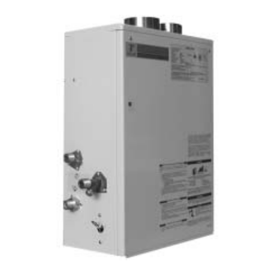
T-KD20
Installation Manual and Owner's Guide
Flash Water Heater
Model T-KD20
Suitable for potable water heating and space heating
Indoor Installation Only
FEATURING
•
ENDLESS HOT WATER
•
ON DEMAND
•
COMPACT, SPACE SAVING
•
ENERGY CONSERVING
•
COMPUTER CONTROLS
•
COMPUTERIZED SAFETY
•
NO PILOT LIGHT
Takagi Industrial Co. USA Inc.
6 Goddard
Irvine, CA 92618
Toll Free (888) 882-5244
www.takagi-usa.com
Instantaneous Water Heater
FOR YOUR SAFETY
must be installed and serviced by a
qualified professional service technician
or licensed person, in water heater
installation. Operation creates carbon
monoxide gas and flue gases, which
can cause serious injury or death.
Improper installation and/or operation,
or installation by an unqualified person,
will void warranty.
WARNING
: If the information in this
manual is not followed exactly, a fire or
explosion may result, causing property
damage, personal injury or death.
•
Do not store or use gasoline or other
flammable vapors or liquids in the
vicinity of this or any other gas
appliance.
•
WHAT TO DO IF YOU SMELL GAS
•
Do not use any appliance.
•
Do not touch any electrical
switch
in your building.
•
Immediately contact your gas
supplier
location.
supplier's instructions.
•
If you cannot reach your gas
supplier,
department.
•
Installation and service must be
performed by a qualified installer,
service agency or the gas supplier.
- This product
do not use any phone
,
from
another
Follow
the
call
the
gas
fire
Advertisement
Table of Contents

Related Manuals for Takagi T-KD20


Summary of Contents for Takagi T-KD20
- Page 1 COMPUTERIZED SAFETY • supplier, call fire NO PILOT LIGHT department. Takagi Industrial Co. USA Inc. 6 Goddard • Installation and service must be Irvine, CA 92618 performed by a qualified installer, Toll Free (888) 882-5244 service agency or the gas supplier.
-
Page 2: Table Of Contents
Gas Supplier. Exploded Diagrams………………………. 24-27 • Check the rating plate to insure this Parts List………………………………….. product matches your specifications. Flow Chart……………………………….. • Takagi - USA is constantly improving our products, therefore specifications subject to change without prior notice. -
Page 3: For Your Safety
5. If a problem should occur, turn off all hot water taps temperature. All Takagi products flue gas vents are and turn off the gas. Call a trained technician, the positive pressure, it requires perfect seal of all vent pipe Gas Company, or the manufacturer. -
Page 4: Operation
Flow To turn on the Flash water heater 1. Open a hot water tap, or turn on water demanding The flow rate through the T-KD20 is limited to a appliance. maximum of 6.9 GPM. The temperature setting, along 2. Unit will detect flow, burners will ignite, “Fire On”... -
Page 5: Freeze Protection
Please keep this owner’s manual in a safe extremely cold weather. This will void your warranty and place for future reference. Copies of this Takagi Industrial Co. USA Inc. will not be responsible manual are available from TAKAGI-USA for any damage that occurs. -
Page 6: Electrical Connections
A green screw is provided in the junction box for the grounding connection. Electrical Connections The T-KD20 requires a 60 Hz 120 VAC electrical power supply, and it should be properly grounded in accordance with the most recent edition of the National Electrical Code, ANSI/NFPA 70 and any local codes. - Page 7 Electrical Rating 120 VAC, 60 Hz, 0.8 A. Note : If any of the original wiring supplied with this appliance must be replaced, it must be replaced with appliance wiring material (180c) or its equivalent. Wires are available through the manufacturer.
-
Page 9: Gas Supply Piping
Gas Supply Piping Insufficient gas supply pressure can cause the Flash Water Heater to lose efficiency or not work at all. Attention: Proper gas pressure is important but gas WARNING: Fire or explosion may result if the maximum volume is more critical than pressure. Right volume gas supply pressures are exceeded. -
Page 10: Water Plumbing
Water Piping Contact the water supplier or a local plumbing inspector on how to control this situation. Important: Purge the water line of air, and clean the Follow local guidelines for the length of the plumbing line in order to ensure that there is enough water filter before initial operation. -
Page 11: Wall Hanging Installation
¼” per foot. The unit should be vented out to directly through a wall. If the unit will be vented through a wall, use Takagi USA Inc. optional part, the TK-TV05 vent terminator, or an equal vent terminator that approved by UL or CSA. -
Page 12: Combustion Air Supply
7. Turn on the electrical power to the appliance. 8. Turn on any tap, and the T-KD20 will initiate itself. 9. If the appliance will not operate, follow the instructions in the “Turning Off the Gas Supply to the Appliance”... -
Page 13: Maintenance
Close the manual valve on the gas inlet line. Turn off the power supply. Troubleshooting Water Isn’t Hot Enough The T-KD20 can burn gas at a maximum input rate of 195,000 BTUH. This puts a limit on the Manifold pressure tap possible... - Page 14 GFCI and the circuit plate. Contact Takagi Industrial Company for Instructions. Error Codes All Takagi units are self-diagnostic for errors. If there is a problem with the installation or the unit, it will give a signal, through a pair...
-
Page 15: Applications
• The FLASH T-KD20 can be used to supply potable water and space heating and shall not be connected to any heating system or component(s) previously used with non-potable water where any chemicals were added to the water heating appliances. - Page 16 necessary safety and auxiliary equipment to conform to code requirements and design practice. For more details, contact Technical Department at (888) 882-5244 Dual-purpose hot water heating (Domestic and Heating): Pressure Relief Valve Air Vent Pump Expansion Tank Radiant, Hydro or Baseboard Domestic Heating Equipment.
-
Page 17: Storage Tank
Pressure relief valve Pump The maximum flow rate through the T-KD20 is 6.9 GPM. If it is necessary to achieve higher flow rates for longer periods of time, then it can be installed in conjunction with a storage tank. A pump will be necessary to keep the water hot. We suggest a pump of 1/12 hp or greater depending on the system. -
Page 18: For Your Safety Read Before Operating
FOR YOUR SAFETY READ BEFORE OPERATING WARNING: If you do not follow these instructions exactly, a fire or explosion may result causing property damage, personal injury or loss of life. A. This water heater does not have a pilot. It is equipped with an ignition device that automatically lights the burner. - Page 19 WA RN I N G The outlet hot water temperature of the T-KD20 water heater is factory set 120 ° F. WARNING: Use this heater at your own risk. The set outlet water temperature can cause severe burns instantly or death from scalds.
- Page 20 For technical support contact Takagi toll free at (888) 882-5244, or check our website at www.takagi-usa.com.
-
Page 21: Optional Items
TK-TV03 Vent Damper TK-TV05 Vent Terminator The TK-TV03 Vent Damper This terminator can be used prevents the backflow of air where a T-KD20 is going to through the exhaust vent. be vented out through a wall. This also This is an AGA approved part approved part of the unit. -
Page 22: Dipswitch Settings
T-KD20 Dipswitch Temperature Settings In the following dipswitch diagrams, the direction in which the head of the dipswitch should be pointing is represented with black. Indoor NG Dipswitch Settings NG Indoor Temperature Settings ° F ° F 105° F 112° F... -
Page 23: Indoor Lp Dipswitch Settings
Indoor LP Dipswitch Settings LP Indoor Temperature Settings 105° F 112° F 120° F 180° F ERROR Outdoor LP Dipswitch Settings LP Outdoor Temperature Settings 105° F 112° F 120° F 180° F ERROR... -
Page 24: Exploded Diagrams
Computer board assembly... - Page 25 Case assembly...
- Page 26 Burner assembly...
- Page 27 Waterway assembly...
-
Page 28: Parts List
T - KD20 PARTS LIST CASE ASSEMBLY 46 SCREW BACK GUARD PANEL ASSEMBLY 47 SPARK ELECTRODE HOLDER FRONT COVER 48 SPARK ELECTRODE FIXING PLATE 49 FLAME SENSOR TRANSFORMER 50 SCREW JUNCTION BOX 51 DAMPER JUNCTION BOX COVER 52 WIRE HOLDER SCREW 53 SCREW SCREW (COATED) -
Page 29: Flow Chart
Flow Rate vs. Temperature Hot Water Out GPM vs. Output Temperature for Various Input Temperature 40 F 50 F 60 F 70 F Output Temperature...
Need help?
Do you have a question about the T-KD20 and is the answer not in the manual?
Questions and answers