Table of Contents
Advertisement
Quick Links
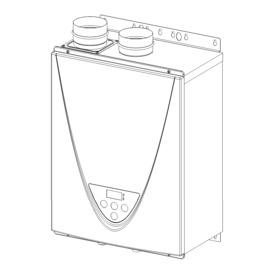
On-Demand Water Heater
Installation Manual and Owner's Guide
R
D
Gas Tankless Water Heater
Suitable for potable water heating and space-heating
Please refer to local codes for space-heating compliance.
FEATURING
• ENDLESS HOT WATER
• ON-DEMAND USAGE
• COMPACT, SPACE SAVING
• ENERGY CONSERVATION
• COMPUTERIZED SAFETY
• NO PILOT LIGHT
• EASY-LINK SYSTEM*
• MULTI-UNIT SYSTEM*
• COMMERCIAL GRADE COPPER*
*(T-H3-DV / 540H model only)
ANSI Z21.10.3 and CSA 4.3
R
T-H3-DV / 540H
model only
TM
Models
T-H3J-DV / 240H
T-H3S-DV / 340H
T-H3-DV / 540H
If the information in these
instructions is not followed
exactly, a fire or explosion may
result causing property damage,
WARNING
personal injury or death.
- Do not store or use gasoline or other
flammable vapors and liquids in the vicinity
of this or any other appliance.
- WHAT TO DO IF YOU SMELL GAS
• Do not try to light any appliance.
• Do not touch any electric switch, do not
use any phone in your building.
• Immediately call your gas supplier from
a neighbor's phone. Follow the gas
supplier's instructions.
• If you cannot reach your gas supplier, call
the fire department.
- Installation and service must be performed
by a qualified installer, service agency or the
gas supplier.
If you have any questions, please
call 1-888-479-8324
89V012-3
REV. 03 (04-15)
Advertisement
Table of Contents

Related Manuals for Takagi T-H3J-DV / 240H


Summary of Contents for Takagi T-H3J-DV / 240H
- Page 1 On-Demand Water Heater Installation Manual and Owner’s Guide ANSI Z21.10.3 and CSA 4.3 Models T-H3J-DV / 240H T-H3S-DV / 340H T-H3-DV / 540H T-H3-DV / 540H model only If the information in these instructions is not followed exactly, a fire or explosion may...
-
Page 2: Table Of Contents
Contents CONTENTS Installation Manual SPECIFICATIONS .......................... 4 INTRODUCTION .......................... 5 SAFETY GUIDELINES ........................6 INSTALLATION ..........................7 General.............................7 Clearances..........................9 Included accessories........................9 Optional items..........................9 Warning for installations......................11 High-altitude installations......................12 Venting Instructions.......................13 Gas supply and gas pipe sizing....................23 Water connections........................25 Condensate drain........................26 Electrical connections......................28 Easy-Link System........................29 Multi-Unit System........................33... -
Page 3: Installation Manual
Installation Manual Installation Manual CONGRATULATIONS Congratulations and thank you for choosing our tankless water heater. Before use, we recommend that you read through this safety manual carefully. Please refer to the back of the manual for details about the warranty. Keep this manual for future reference. If you lose the manual, contact the manufacturer, your local distributor, or download from the manufacturer's website. -
Page 4: Specifications
Installation Manual Specifications SPECIFICATIONS Model T-H3J-DV / 240H T-H3S-DV / 340H T-H3-DV / 540H Natural Gas Input Min.: 15,000 Min.: 15,000 Min.: 15,000 BTU/h (Operating Range) Max.: 160,000 Max.: 180,000 Max.: 199,000 Propane Input Min.: 13,000 Min.: 13,000 Min.: 13,000... -
Page 5: Introduction
• These high-efficiency models have a built-in secondary heat exchanger that absorbs latent heat from the exhaust gas. • The T-H3J-DV / 240H, T-H3S-DV / 340H and T-H3-DV / 540H models are only to be installed indoors. • The principle behind tankless water heaters is simple:... -
Page 6: Safety Guidelines
Installation Manual Safety Guidelines SAFETY GUIDELINES SAFETY DEFINITION Indicates an imminently hazardous situation which, if not avoided, will result in death or serious injury. DANGER Indicates an imminently hazardous situation which, if not avoided, could result in death or serious injury. WARNING Indicates an imminently hazardous situation which, if not avoided, could result in minor or moderate injury. -
Page 7: Installation
Regular maintenance is recommended for these types of environments. 9. T-H3J-DV / 240H, T-H3S-DV / 340H, and T-H3-DV / 540H models are to be installed indoors only. These units are equipped with a thermistor and hi-limit switch for the exhaust gas, detecting excess temperatures within the flue and enabling the unit to safely stop operations if needed. - Page 8 Installation Manual Installation • Installation and service must be performed by a qualified installer (for example, a licensed plumber or gas fitter), otherwise the warranty will be void. WARNING • The installer (licensed professional) is responsible for the correct installation of the water heater and for compliance with all national, state / provincial, and local codes.
-
Page 9: Clearances
Maintain all clearances around Back Side the water heater. Front Side Bottom Model Bottom Front Back Sides T-H3J-DV / 240H 305 mm 305 mm 102 mm* 13 mm 76 mm T-H3S-DV / 340H (12 in.) (12 in.) (4 in.) (0.5 in.) (3 in.) T-H3-DV / 540H *610 mm (24 inches) recommended for maintenance. - Page 10 Installation Manual Installation 1. Temperature remote controller: 2. N/A TM-RE42-Standard model/TM-RE40 The temperature remote controller has three functions. It allows the output temperature from the water heater to be adjusted, and it also works as a diagnostic tool and it provides a concise error code whenever there is a problem with the unit.
-
Page 11: Warning For Installations
Installation Manual Installation 7. Non-return valve: 9008847005 It is a must-have item for common venting system. It prevents the escape of combustion gas through non-operating appliances. (Refer to p. 18 and 19.) WARNING FOR INSTALLATIONS FOR YOUR SAFETY, READ BEFORE INSTALLATION: • Do not install the heater where water, debris, or flammable vapors may get into the flue terminal. -
Page 12: High-Altitude Installations
No. 4 : ON NOTE: The dark squares indicate the direction the DIP switches should be set to. *The maximum allowable altitude is 3,100 m (10,100 ft.) T-H3J-DV / 240H and T-H3S-DV / 340H T-H3-DV / 540H Computer board Computer board... -
Page 13: Venting Instructions
CAUTION applicable national and local codes. T-H3J-DV / 240H, T-H3S-DV / 340H, and T-H3-DV / 540H models must be vented in accordance with the section “Venting of Equipment" of the latest edition of CSA B149.1, Natural Gas and propane installation code, as well as applicable local building codes. - Page 14 Installation -DIP switch settings for Vent length- Set DIP switches shown in the table below depending on the vent length. 76 mm (3") venting T-H3J-DV / 240H T-H3-DV / 540H Vent length T-H3S-DV / 340H (Upper bank of DIP switches)
- Page 15 Installation Manual Installation • The maximum length of exhaust vent piping must not exceed 21.3 m (70 ft.) for 76 mm (3”) venting, which depends on the elevation where the water heater is installed. 30.5 m (100 ft.) for 102 mm (4”) venting (deducting 1.5 m (5 ft.) for each elbow used in the venting system). Do not use more than 5 elbows.
- Page 16 Installation Manual Installation <How to install plastic venting> 76 mm (3") vent connection Diagram 1. Connect a 76 mm (3") coupling directly on 76 mm (3”) the exhaust and intake vent collars of the 76 mm (3”) plastic straight pipe plastic straight pipe water heater. 2.
- Page 17 Installation Manual Installation Diameter Max. No. of Elbows Max. Vertical and Horizontal (Total) Vent Length 102 mm (4 in.) 30.5 m (100 ft.) *For each elbow added, deduct 1.5 m (5 ft.) from max. vent length. No. of Elbows Max. Vertical or Horizontal Vent Length 30.5 m (100 ft.) 29.0 m (95 ft.) 27.4 m (90 ft.)
- Page 18 • The water heaters must all be direct-vented. • For common-venting pieces and components, the manufacturer recommends Centrotherm's vent line. Allowable models for common-venting T-H3J-DV / 240H T-H3S-DV / 340H T-H3-DV / 540H • Check with the current version of the Canadian gas code or authority having jurisdiction to see if common venting is approved in your area.
- Page 19 Common-venting system Max. DIP switch settings Vent Max. Vertical and No.of Diameter* Horizontal T-H3J-DV / 240H T-H3-DV / 540H water (Total) Vent Length** (L) T-H3S-DV / 340H (Upper bank of DIP switches) heaters 110 mm 7.6 m (25 ft.) (4 in.
-
Page 20: Vent Termination Clearances
Installation Manual Installation -Vent termination clearances- INSIDE CORNER DETAIL Vent terminal Air supply inlet Area where is not permitted Gas meter / regulator Canada U.S.A Direct-vent and other Direct- Other than than Direct-vent vent Direct-vent Clearance above grade, veranda, porch, deck, or 1 foot 1 foot 1 foot... - Page 21 Installation Manual Installation -For sidewall terminations- Please follow all local and national codes in regards to proper termination clearances. In the absence of such codes, the clearances below can be used as guidelines. Local codes supersede these guidelines. CAUTION For multiple sidewall exhaust terminations (e.g. Multi-Unit Systems), an exhaust termination must be at least 305mm 610 mm 305 mm...
- Page 22 Exhaust and/or direct-vent sidewall terminations should be at least 610 mm (2 ft.) away from an opposite surface/ wall. Do not place the termination directly in front of an opening into a building 610 mm 2 ft.) Exhaust termination -For rooftop terminations- 610 mm (2 ft) Air intake...
-
Page 23: Gas Supply And Gas Pipe Sizing
Installation Manual Installation GAS SUPPLY AND GAS PIPE SIZING -General- • Check that the type of gas matches the rating plate first. • Ensure that any and all gas regulators used are operating properly and providing gas pressures within the specified range shown below. Excess gas inlet pressure may cause serious accidents. - Page 24 Installation Manual Installation -Natural Gas Supply Piping- Maximum delivery Capacity of Cubic Feet of Gas per Hour of IPS Pipe carrying Natural Gas with 0.60 Specific Gravity Based on Pressure Drop of 0.5" W.C. Based on Energy Content of 1,000 BTU/Cubic ft.: The water heater requires 160 Cubic ft./hr for the T-H3J-DV / 240H, 180 Cubic ft./hr for the T-H3S-DV / 340H, and 199 Cubic ft./hr for the T-H3-DV / 540H.
-
Page 25: Water Connections
Installation Manual Installation -Measuring inlet gas pressure- 1. Turn off all electric power to the water heater if service is to be performed. 2. Turn the manual gas valve located on the outside of the unit clockwise to the off position. The water heater cannot perform properly without sufficient inlet gas pressure. -
Page 26: Condensate Drain
• The pressure relief valve must conform to CAN 1-4.4 and installation must follow local codes. • The discharge capacity must be at least 160,000 BTU/h for the T-H3J-DV / 240H, 180,000 BTU/h for the T-H3S-DV / 340H, and 199,000 BTU/h for the T-H3-DV / 540H. - Page 27 Installation Manual Installation -Condensate Drain Connections- Discharge condensate (acidic water) in accordance with all local codes and common safety practices. WARNING The water heater is a high efficiency condensing water heater that produces condensate (acidic water). The acidic condensate generated in the secondary heat exchanger can be neutralized by the Neutralizer accessory, part number TH-NT01.
-
Page 28: Electrical Connections
Installation Manual Installation • The condensate drain is at atmospheric pressure (non-pressurized) and therefore must be allowed to drain freely with gravity only. Please ensure that there are no blockages along the condensate drain tube. All portions of the WARNING condensate drain (neutralizer and drain tube) must be at a lower elevation than the water heater to prevent condensate water from building up inside the heat exchanger. -
Page 29: Easy-Link System
Installation Manual Installation EASY-LINK SYSTEM (Available on the T-H3-DV / 540H only) -General- The T-H3-DV / 540H water heaters can be connected with allowable heaters (see the table below) with communication cables to work as a multiple-unit manifold system. • The Easy-Link System allows up to 4 units to manifold together. • A communication cable (gray color) comes with each T-H3-DV / 540H model. - Page 30 Installation Manual Installation 3. Select one unit to be the “PARENT” unit. The “PARENT” unit should be one of the end units. 4. “PARENT” unit: Locate the two banks of DIP switches at the bottom left of the computer board of the unit that you select to be the “PARENT”...
- Page 31 Installation Manual Installation Either a temperature controller or a remote controller is required for the Easy- NOTICE Link System for ease of usage and maintenance. (C) Examples of incorrect settings and /or connections CASE 1: Wrong DIP switch setting on the "PARENT" unit • Unless you change DIP switch No.
- Page 32 Installation Manual Installation CASE 3: Wrong connections between the "CHILD-1" unit and the "CHILD-2" unit • If you connect the “PARENT” connector of the “CHILD-1” unit to the “1” connector of the “CHILD-2” unit, the “CHILD-2” unit will operate as an individual unit, and will not be part of the Easy-Link System.
-
Page 33: Multi-Unit System
Installation Manual Installation MULTI-UNIT SYSTEM Multiple T-H3-DV / 540H units can be combined for a Multi-Unit System, along with the Multi- Unit Controller (TM-MC02). The Multi-Unit Controller can control 2 to 20 units. For a 20-unit system, the computer can modulate between the usages of 13,000 BTU/h (Propane) or 15,000 BTU/h (Natural gas) to 4.0 Million BTU/h. -
Page 34: Applications
Installation Manual Applications APPLICATIONS -Space-Heating Applications- • In order to purge air in water pipes within a closed-loop system, an air vent and air separator should be installed in the system. Required circulation flow rates are labeled next to each application diagram. These flow rate requirements must be followed. - Page 35 -Dual-purpose hot water heating- (Domestic and Space Heating): (Domestic and Space Heating): Diagramatic layout of Radiant Heating and Domestic Water Heater. 4" gas exhaust vent Cold water supply (Discharge must comply with local and state codes). Cannot be common vented Check valve will have with other appliances 1/8"...
-
Page 36: Initial Operation
Installation Manual Initial Operation INITIAL OPERATION FOR YOUR SAFETY, READ BEFORE OPERATING • Check the GAS and WATER CONNECTIONS for leaks before firing unit for the first time. • Open the main gas supply valve to the unit using only your hand to avoid any spark. Never use tools. -
Page 37: Owner's Guide
Owner's Guide Owner's Guide CONGRATULATIONS Congratulations and thank you for choosing our tankless water heater. Before use, we recommend that you read through this safety manual carefully. Please refer to the back of the manual for details about the warranty. Keep this manual for future reference. If you lose the manual, contact the manufacturer, your local distributor, or download from the manufacturer's website. -
Page 38: Operating Safety
Owner's Guide Operating Safety OPERATING SAFETY FOR YOUR SAFETY READ BEFORE OPERATING WARNING: If you do not follow these instructions exactly, a fire or explosion may result causing property damage, personal injury or loss of life. A. This water heater does not have a pilot. It is equipped with an ignition device that automatically lights the burner. - Page 39 Owner's Guide Operating Safety DANGER Vapors from flammable liquids will explode and catch fire causing death or severe burns. Do not use or store flammable products such as gasoline, solvents or adhesives in the same room or area near the water heater. Keep flammable products: Vapors: 1.
-
Page 40: Normal Operation
Owner's Guide Normal Operation NORMAL OPERATION TEMPERATURE CONTROLLER and REMOTE CONTROLLER The illustration below, shows examples of the controllers. The exact display may differ from examples. Temperature controller Remote controller Display for Temperature "INFO" Button When the STAND BY LED is ON, the hot water temperature will be Each time the button is pressed, displayed. -
Page 41: Temperature Settings
63 °C (145 °F). 4. Press the "HOT" button to set up to 70 °C (160 °F). TEMPERATURE TABLE OF CONTROLLER a) For T-H3J-DV / 240H and T-H3S-DV / 340H °C °F 100 105 110 115 120* 125 130 135 140 b) For T-H3-DV / 540H °C... -
Page 42: Additional Features
Owner's Guide Normal Operation ADDITIONAL FEATURES -Information mode- You can get some information about the water heater condition by pressing the "INFO" button. For more information, follow the procedures below: Screen on the controller Operation Temperature controller Remote controller Inlet water temperature First of all, inlet water temperature will be displayed on the controller by pressing the "INFO"... -
Page 43: Temperature Settings On The Pcb (Without Remote Controller)
DIP switch settings. • The temperature has been preset at the factory to 50 °C (120 °F). T-H3J-DV / 240H and T-H3S-DV /340H Computer board 50 °C (120 °F) 60 °C (140 °F) -
Page 44: Flow
• The freeze protection system will activate when the freeze protection thermostat senses temperature at 2.5 °C (36.5 °F) or lower. • For the T-H3J-DV / 240H , T-H3S-DV / 340H and T-H3-DV / 540H models: • In indoor installations, freezing issues can only occur if cold air enters through the venting into the heat exchanger, whether by negative pressures within the installation location or by strong outside winds. -
Page 45: Maintenance And Service
Owner's Guide Normal Operation MAINTENANCE AND SERVICE Turn off the electrical power supply and close the manual gas shutoff valve and the manual water control valve before servicing. WARNING • Clean the cold-water inlet filter. (Refer to Unit draining and filter cleaning section in this page.) • Be sure that all openings for combustion and ventilation air are not blocked. -
Page 46: Descaling
Descaling the Unit Hard water is a severe problem for the copper coils inside heat exchangers. Heat exchanger failure due to scale buildup from hard water conditions is NOT covered by warranty. It is highly suggested that a scale inhibitor be installed before the cold water inlet after this procedure is done. 1) TOOLS Gather the following materials: a. -
Page 47: Troubleshooting
Owner's Guide Troubleshooting TROUBLESHOOTING GENERAL PROBLEM SOLUTIONS It takes long time to • The time it takes to deliver hot water from the water heater to your get hot water at the fixtures depends on the length of piping between the two. The longer fixtures. - Page 48 Owner's Guide Troubleshooting PROBLEM SOLUTIONS Unit does not ignite • Is the power on the water heater? • Is the gas on? when water goes through • Is the flow rate over 1.9 L/min (0.5 GPM)? (p. 40) the unit. • Check for the filter on cold water inlet.
-
Page 49: Error Codes
• If there is a problem with the installation or the unit, the error code will be displayed on the temperature controller and remote controller. • Consult with the table on the following pages for the description of each error code. Error code indicator on T-H3J-DV / 240H and T-H3-DV / 540H the temperature controller T-H3S-DV / 340H... - Page 50 Owner's Guide Troubleshooting -Fault Analysis of Error Codes- If the error code is displayed on the computer board of the water heater or remote controller and/or temperature controller, please check the following. After checking, consult with the manufacturer. Green Malfunction Remote Diagnosis description...
- Page 51 Owner's Guide Troubleshooting Green Malfunction Remote Diagnosis description Two Times Outlet thermistor failure (T-H3J-DV / 240H and T-H3S-DV / 340H only) Heat exchanger thermistor failure • Check for connection/breakage of wires and/or (T-H3-DV / 540H debris on thermistor (Part #407, 408, 411, 715). only) • Check the resistance.
- Page 52 Owner's Guide Troubleshooting Green Malfunction Remote Diagnosis description Miscommunication • Check the model type of the remote controller. between water • Inspect the connections between the water heater heater and remote and remote controller. controller • Check the power supply of the water heater. Miscommunication • Inspect the connections between the water heater between water...
-
Page 53: Components Diagram
Owner's Guide Components Diagram COMPONENTS DIAGRAM Case assembly Temperature Temperature controller remote controller TM-RE42 Page... - Page 54 Owner's Guide Components Diagram Computer board assembly T-H3J-DV / 240H and T-H3S-DV / 340H T-H3-DV / 540H 707 722 Surge box assembly Page...
- Page 55 Owner's Guide Components Diagram Burner assembly Burner assembly 109 111 Manifold assembly T-H3-DV / 540H Page...
- Page 56 Owner's Guide Components Diagram Water Way assembly T-H3-DV / 540H T-H3J-DV / 240H and T-H3S-DV /340H Bypass section (T-H3-DV / 540H) Water outlet section Water inlet section Page...
-
Page 57: Parts List
EK163 O-ring P18 NBR (Black) EZP18 O-ring P20 NBR (Black) EK042 Primary heat exchanger assembly for T-H3J-DV / 240H and T-H3S-DV / 340H EK252 Primary heat exchanger assembly for T-H3-DV / 540H EK250 Flow adjustment valve / Flow sensor EK129... - Page 58 Rubber grommet EX00B Surge box EK280 120 VAC wire EK146 120 VAC Power ON-OFF switch EKK4V Remote controller wire for T-H3J-DV / 240H and T-H3S-DV / 340H EK189 for T-H3-DV / 540H EK165 Gas valve wire EK168 Flame rod wire EK166...
-
Page 59: Output Temperature Chart
Owner's Guide Output Temperature Chart OUTPUT TEMPERATURE CHART Chart is based on properly sized gas line T-H3J-DV / 240H Output Temperature vs. GPM (Max. 6.6 GPM) with Various Inlet Water Temperature Set Temp. T-H3S-DV / 340H Output Temperature vs. GPM (Max. 8.0 GPM) with Various Inlet Water Temperature Set Temp. -
Page 60: Limited Warranty
(3) In all applications, the total of length of operation time must be less than 3,000 hours for the T-H3J-DV / 240H and T-H3S-DV / 340H, and less than 9,000 hours for the T-H3-DV / 540H. (4) Includes dual-purpose applications (combination heating and domestic). - Page 61 • Freeze damage that occurs without taking proper preventive measures as described in the installation manual. • Condensate damage due to improperly installed or lack of a condensate trap (drain). • Any product not installed in compliance with all applicable local & provincial codes, ordinances, and good trade practices. • Any product sold to or installed in areas outside of the fifty states (and the District of Columbia) of the United States of America and Canada. • Any product installed in applications that cause the water heater to activate more than 300 times per day. (This averages to an activation every 5 minutes in a 24-hour period.) • Any failures that are not due to defects in materials or workmanship (mechanical and/or electrical parts). • Damages due to improper installation: • Gas: incorrect gas pipe sizing, incorrect gas meter sizing, incorrect gas type, and/or gas pressures that fall outside the product’s specified range. • Water: incorrect water pipe sizing, water pressures that fall outside the product’s specified range, recirculation flow rates that fall outside the product’s specified range (air removal), and/or lack of proper methods of air removal in a closed-loop, circulation system.
- Page 62 If you have any questions, please call 1-888-479-8324 89V012-3...
Need help?
Do you have a question about the T-H3J-DV / 240H and is the answer not in the manual?
Questions and answers