
Related Manuals for Evo EV522T


Summary of Contents for Evo EV522T
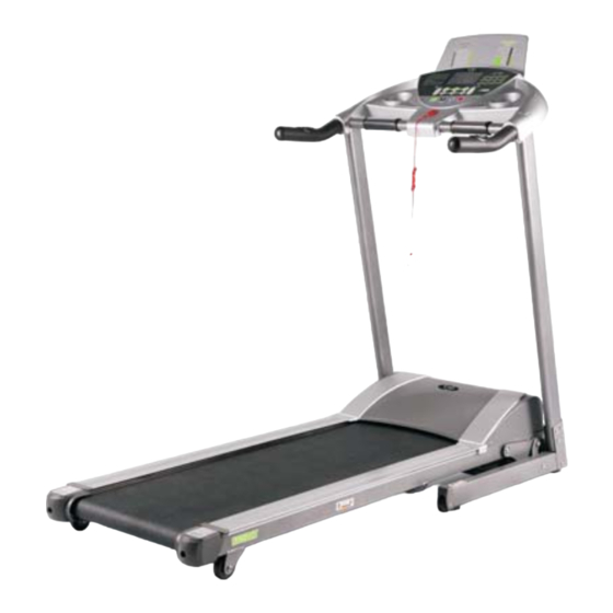
- Page 1 OWNER’S MANUAL EV522T RETAIN OWNER'S MANUAL FOR FUTURE REFERENCE Service call 1300 796 636 www.evofitness.net.au...
-
Page 2: Table Of Contents
TABLE OF CONTENTS SAFETY ------------ p1~p2 WARM-UP & COOL DOWN ------------ UNPACKING & ASSEMBLY ------------ ASSEMBLY DRAWING ------------ p5-p6 FOLDING INSTRUCTION ------------ INCLINE MANUAL ------------ COMPUTER OPERATIONS ------------ p9-p12 Control panel function, control panel operation BELT ADJUSTMENT ------------- CARE & MAINTENANCE ------------- LUBRICATION MAINTENANCE ------------... -
Page 3: Safety
SAFETY IMPORTANT: Read all instructions and warnings before using the treadmill WARNING! : Do not attempt to use this treadmill with a voltage adapter. Do not attempt to use this treadmill with an extension cord. CONSULT A PHYSICIAN IMMEDIATELY Warning: before starting any exercise program consult your physician. This is especially important for individuals over the age of 35 or persons with pre-existing health problems. - Page 4 SAFETY TARGET HEART RATE ZONE You do not want to workout at your maximum heart rate. The recommended Heart Rate Zone is a percentage of your maximum heart rate. Between 60% and 75% of your maximum heart rate. Lower limit of Target Heart Rate Zone =maximum heart rate X 0.6 Upper limit of Target Heart Rate Zone =Maximum heart rate X0.75...
-
Page 5: Warm-Up & Cool Down
WARM-UP & COOL DOWN WARM- UP& COOL-DOWN A successful exercise program consists of a warm up, aerobic exercise, and a cool down. Warming up is an important part of your workout, and should begin every session. It prepares your body for more strenuous exercise by heating up and stretching out your muscles. -
Page 6: Unpacking & Assembly
UNPACKING & ASSEMBLY WARNING!: Use extreme caution when assembling the treadmill. Failure to do so could result in injury NOTE: Each step number in the assembly instructions tells you what you will be doing. Read and understand instructions thoroughly before assembling the treadmill. 1. -
Page 7: Assembly Drawing
ASSEMBLY DRAWING Step 1 Step 2... - Page 8 Step 3 STEP 4 Note:Please check that all of the parts are assembled correctly and the plug is fitted into wall correctly...
-
Page 9: Folding Instruction
Folding instruction Step 1 Lift up the machine deck and push forward until you hear a “click” which means that the safety casing has locked into the pneumatic cylinder. Unfolding instruction ruction Step 2 Push the deck slightly forward and STEP 2 kick lightly on the center of the pneumatic cylinder. -
Page 10: Incline Manual
INCLINE MANUAL PICTURE 1 PICTURE 2 S: INCLINE INSTRUCTION " 、 " “+”、“-” INCLINE+” INCLINE-” and on left handrail are the incline increase and decrease buttons . To adjust the incline while the treadmill is running you can also press the incline shortcut keys on the console. -
Page 11: Computer Operations
COMPUTER OPERATIONS CONTROL PANEL FUNCTION Window display:1 LCD window CALORIES: Indicates START: Start the treadmill estimated calories burnt SPEED: Indicates kph in 0.1 PULSE: estimated heart rate STOP: Stop the treadmill increments INCLINE: Indicates incline in percent of grade in 1% increments DISTANCE: Indicates km travelled in 0.1 increment TIME: Indicates time you workout, can be set to countdown... - Page 12 By Pressing mode key under manual mode you can enter into time count down mode Time window lights up and indicates preliminary time 30:00. Press start to run the machine Press mode key under time count down mode enter into distance count down mode Window lights up and indicates preliminary distance 1.0 Pressing speed +/-...
- Page 13 TIME INTERVAL set time / 10 = every grade time mode SPEED INCLINE SPEED INCLINE SPEED INCLINE SPEED INCLINE SPEED INCLINE SPEED INCLINE SPEED INCLINE SPEED INCLINE SPEED INCLINE SPEED INCLINE SPEED INCLINE SPEED INCLINE...
- Page 14 . Safety key function “↓ ”, “ ” Pull off the safety key, the LCD windows show the buzzer sound BIBI-BI the data of other windows keep unchanged) the motor will stop moving 7. T he display range of numerical value :...
-
Page 15: Belt Adjustment
BELT ADJUSTMENT BELT ADJUSTMENT You may need to adjust the running belt during the first few weeks of use. All running belts are properly set at the factory. It may stretch or be off-center after use. Stretching is normal during the break-in period. -
Page 16: Care & Maintenance
CARE & MAINTENANCE WARNING!:To prevent electrical shock, be certain the treadmill is turned off and unplugged before cleaning or routine maintenance. RUNNING BELT AND RUNNING DECK LUBRICATION For maximum treadmill life, this treadmill needs a routine lubrication as part of a general maintenance for the machine. -
Page 17: Lubrication Maintenance
LUBRICATION MAINTENANCE It is important to take good care of your treadmill deck (the walking surface underneath the belt). A good silicone lubrication will also improve the performance of your treadmill. NOTE: Use the silicone that is supplied with the treadmill. Additional HEALTHSTREAM silicone lubricant can be purchased from your retail store. -
Page 18: Trouble Shooting
TROUBLE SHOOTING Fault Code Fault Description Fault Processing The computer has The control board stops and enters into error abnormal code. The console will display “E1” and beeps 3 communication after sounds starting Possible Reasons: Communication Abnormal: control computer abnormal communication after start The motor wire The computer shows fault code “E2”. -
Page 19: Exploded Drawing
EXPLODED DRAWING... -
Page 20: Parts List
PARTS LIST DESCRIPTION REMARK DESCRIPTION REMARK MAIN FRAME TRANSPORT WHEEL ¡ Ó 8 .2* ¡ Ó 5 1.5*20 ∮ 9*¡ Ó 6 2*23.5 BASE FRAME ADJUSTABLE WHEEL LEFT UPRIGHT 26 POWER SWITCH 250V/15A RED ∮ 38 *t1.5 RIGHT UPRIGHT 27 INNER END CAP ∮... - Page 21 PARTS LIST DESCRIPTION REMARK DESCRIPTION REMARK BOLT M10*45 WASHER ¡ Ó 9 * ¡ Ó 1 6*t1.6 BOLT M10*90 WASHER ¡ Ó 6 .6*¡ Ó 1 2*t1.6 ROUND HEAD HEX M8*20 INNER WASHER ¡ Ó 1 4.5*¡ Ó 8 .4*t0.8 BOLT ROUND HEAD HEX M8*35...
Need help?
Do you have a question about the EV522T and is the answer not in the manual?
Questions and answers