Table of Contents
Advertisement
Quick Links
www.opti-ups.com
USER MANUAL
PS-D Line interactive UPS
PS650D / PS1000D / PS1500D / PS2000D
PS1000D-RM / PS1500D-RM
PS1000D-RT / PS1500D-RT / PS2000D-RT
PS3000D-RT / PS5000D-RT / PS7500D-RT / PS10000D-RT
PS3000DL / PS5000DL / PS7500DL
Uninterruptible Power Supply
CONTENTS
1. INTRODUCTION ...........................................................
2. SAFTY INSTRUCTION...............................................
3. SYSTEM DESCRIPTION..............................................
4. OUTLINE DESCRIPTION.............................................
5. CABLE CONNECTION................................................
6. OPERATION .................................................................
7. TROUBLE SHOOTING GUIDE.....................................
8. OPERATION MODES OF THE UPS ............................
9. COMPUTER INTERFACE ............................................
10. SPECIFICATIONS...................................................
1
2
3
7
9
22
23
28
30
32
33
Advertisement
Table of Contents

Subscribe to Our Youtube Channel
Related Manuals for OPTI-UPS PS650D


Summary of Contents for OPTI-UPS PS650D
-
Page 1: Table Of Contents
CONTENTS USER MANUAL 1. INTRODUCTION ..........……..PS-D Line interactive UPS 2. SAFTY INSTRUCTION....……...……………..PS650D / PS1000D / PS1500D / PS2000D 3. SYSTEM DESCRIPTION......……..…..PS1000D-RM / PS1500D-RM 4. OUTLINE DESCRIPTION......……..PS1000D-RT / PS1500D-RT / PS2000D-RT PS3000D-RT / PS5000D-RT / PS7500D-RT / PS10000D-RT 5. -
Page 2: Introduction
1. INTRODUCTION 1.3 Important Notices To be sure that the UPS will be operated correctly, the following items should be 1.1 General Description noticed: The continuity of electrical power is an essential requirement for critical load 1. Read instructions carefully before operating the UPS. operations. - Page 3 2.2 Positioning 2.4 Operation 1. Do not put the UPS on rugged or declined surface. 1. Do not disconnect the mains cable on the UPS system or the building wiring 2. Do not install the UPS system near water or in damp environments. socket outlet during operations since this would cancel the protective earthing of 3.
-
Page 4: System Description
3. Batteries may cause electric shock and have a high short-circuit current. Please 3. SYSTEM DESCRIPTION take the precautionary measures specified below and any other measures 3.1 Front Panel Description for LCD Model necessary when working with batteries: - remove wristwatches, rings and other metal objects - use only tools with insulated grips and handles. -
Page 5: Outline Description
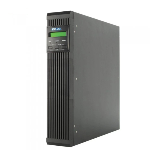
UPS. Beside, it is pressed to confirm and enter the item selected. 4.1 Case Outline 5. Fault LED (red): To indicate the UPS is in fault condition because of inverter PS650D shutdown or over-temperature. 6. Warning LED (yellow): To indicate the UPS is in the status of overload, bypass and battery back-up. - Page 6 PS1000D / PS1500D / PS2000D PS1000D-RT / PS1500D-RT / PS2000D-RT (2U)
- Page 7 PS5000D-RT Rack & Tower Convertible Unit (3U) PS3000D-RT / PS3000DL Rack & Tower Convertible Unit (3U)
- Page 8 PS7500D-RT / PS10000D-RT / PS5000DL / PS7500DL Rack & Tower 4.2 Back View Description Convertible Unit (3U) PS650D 4. Output Socket (NEMA 5-15R 1. USB Interface Port or IEC320) 2. Remote Control (optional) 5. Breaker RJ11 Surge Protection (optional) 6. Input Socket...
- Page 9 PS1000D / PS1500D / PS2000D PS1000D-RM / PS1500D-RM (1U) 1. RS-232 Interface Port 5. Output Socket 4. Output Socket (NEMA 5-15R or 1. RS-232 Interface Port IEC320) 2. Intelligent Slot (SNMP, optional) 6. External Battery Socket ( L ) 2. Intelligent Slot (SNMP, optional) 5.
- Page 10 PS1000D-RT / PS1500D-RT / PS2000D-RT (2U) PS3000D-RT / PS3000DL Convertible Unit (3U) 1. RS-232 Interface Port 6. Fan 1. RS-232 Interface Port 6. Fan 2. Intelligent Slot (SNMP, optional) 7. External Battery Socket ( L ) 2. Intelligent Slot (SNMP, optional) 7.
- Page 11 PS5000D-RT Convertible Unit (3U) PS5000DL / PS7500D-RT / PS7500DL / PS10000D-RT Convertible Unit (3U) 1. RS-232 Interface Port 6. Fan 1. RS-232 Interface Port 6. Fan 2. Intelligent Slot (SNMP, optional) 7. External Battery Socket ( L ) 2. Intelligent Slot (SNMP, optional) 7.
-
Page 12: Cable Connection
6. OPERATION 5. CABLE CONNECTION 6.1 Check Prior to Start Up 5.1 Inspection 1. Ensure the UPS is in a suitable positioning. 1. The system may be installed and wired only by qualified electricians in 2. Check input cord is secured. accordance with applicable safety regulations. - Page 13 2. By pressing the Enter- key and the Down-key simultaneously for 3 1£ ® Rated Spec Menu 2£ ® Status Menu seconds until the buzzer beeps twice, the UPS will start up and Normal LED lights up to indicate the power is from its inverter to the load. 3.
- Page 14 9.Output Voltage/Frequency Set Menu 5£ ® Battery Status Menu A. In this screen, press on/off Control Key to enter the following steps for output voltage or frequency setting. The cursor (→) will pop up to 6£ ® V Output Power Menu 7£...
-
Page 15: Trouble Shooting Guide
7.TROUBLE SHOOTING GUIDE 7.1 For LCD Model UPS STATUS POSSIBLE CAUSE ACTION The following guideline may be helpful for basic problem solving. 1. Reduce the less AC utility power 1. AC utility power critical load in UPS STATUS POSSIBLE CAUSE ACTION fails .The load is failure. -
Page 16: Operation Modes Of The Ups
8. OPERATION MODES OF THE UPS 8.3 AC Utility Failure (Battery Mode) The AC output comes from battery, passing through DC/AC inverter and static 8.1 UPS System Block Diagram switch within the battery backup time. 8.2 Normal Operation There are two main loops when AC utility is normal: the AC loop and the battery charging loop. -
Page 17: Computer Interface
10. SPECIFICATION 9. COMPUTER INTERFACE 9.1 communication interface The communication interface (DB9 port) on the back of the UPS may be connected to a host computer. The port provides communication of RS-232 for monitoring software (like RUPSII or UPSilon 2000 of Megatec Company) The UPS communicates with the computer by sending out RS-232 data streams to one of the serial ports. - Page 19 www.opti-ups.com...
Need help?
Do you have a question about the PS650D and is the answer not in the manual?
Questions and answers