Table of Contents
Advertisement
Advertisement
Table of Contents

Related Manuals for OPTI-UPS VS375C


Summary of Contents for OPTI-UPS VS375C
- Page 1 User’s Guide Value Series Model VS375C, VS575C...
- Page 2 For your records The serial number of your UPS is on the rear panel. You should note the serial number in the space provided below. Retain this booklet as a permanent record of your purchase to aid in identification in the event of theft or loss. Model No: Serial No.: Purchase Date:...
-
Page 3: Limited Warranty
What the warranty covers: We warrant this product to be free from defects in material and workmanship during the warranty period. If a product proves to be defective in material or workmanship during the warranty period, we will at our sole option repair or replace the product with a like product. How long the warranty is effective: For accurate warranty period and conditions, please contact local branch offices or your dealers. - Page 4 Limitation of implied warranties: THERE ARE NO WARRANTIES, EXPRESS OR IMPLIED, WHICH EXTEND BEYOND THE DESCRIPTION CONTAINED HEREIN INCLUDING THE IMPLIED WARRANTY OF MERCHANTABILITY AND FITNESS FOR A PARTICULAR PURPOSE. Exclusion of damages: OUR LIABILITY IS LIMITED TO THE COST OF REPAIR OR REPLACEMENT OF THE PRODUCT.
- Page 5 Life Support: We do not recommend the use of our UPS products for life support equipment or direct care where failure of a UPS product could cause failure of, or diminished effectiveness of the life support equipment or patient care. *Except as expressly provided for by the UPS “Equipment Protection Policy”...
-
Page 7: Important Safety Instructions
GASES. OBSERVE PROPER PRECAUTIONS. ♦ WHEN REPLACING BATTERIES, USE THE SAME NUMBER AND THE FOLLOWING TYPE BATTERIES: SEALED LEAD-ACID MAINTENANCE FREE (VS375C: 1 X 3.5AH/12V; VS575C: 1 X 3.8AH/12V) ♦ PROPER DISPOSAL OF BATTERIES IS REQUIRED. REFER TO YOUR LOCAL... - Page 8 * Remove watches, rings or other metal objects. * Use tools with insulated handles. To reduce the risk of fire, connect only to a circuit provided with 20 amperes maximum branch circuit overcurrent protection in accordance with the National Electrical Code. ANSI/NFPA 70. REPAIRS SHOULD VS375C/VS575C PERFORMED...
- Page 9 VS375C/VS575C FEDERAL COMMUNICATIONS COMMISSION (FCC) WARNING: This equipment has been tested and found to comply with the limits for a Class B digital device, pursuant to Part 15 of the FCC rules. These limits are designed to provide reasonable protection against harmful interference in a residential installation.
-
Page 10: Table Of Contents
Determining How Much Equipment You Can Connect to Your UPS Powering Up Your UPS Connecting Your Equipment to the UPS Operation and Function Test Storage Instructions SPECIFICATIONS Electrical Specifications Mechanical Specifications Environmental Specifications TROUBLESHOOTING Troubleshooting Chart USER REPLACEABLE BATTERY Warning Battery Replacement Procedure for 500VS II VS375C/VS575C... -
Page 11: Overview
VS375C/VS575C INTRODUCTION 1.1 Overview The Value Series of Uninterruptible Power Systems (UPS) was designed to prevent spikes, transients and blackouts from reaching your sensitive equipment. Your equipment include such telecommunication systems. When AC power is present, the UPS filters the power continuously. -
Page 12: Over Voltage And Under Voltage Protection
UPS. A customized schedule can be developed to meet your specific requirements. 1.6 Data-Line Surge Protection The built-in data-line surge suppression on the rear panel completes your system protection. It provides an easy way to protect a network (RJ45) or modem (single line phone) connection from hazardous spikes. VS375C/VS575C... -
Page 13: Ups Controls
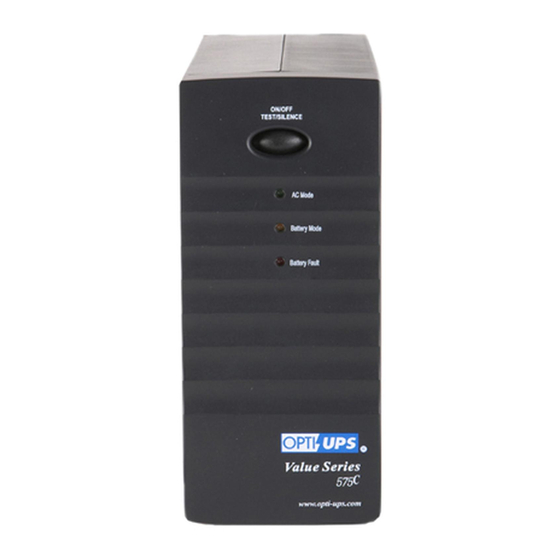
VS375C/VS575C UPS CONTROLS External Views Power On/Off/Test/Silence Button: The On/Off/Test/Silence Button has four functions: When the UPS is off and AC power is present, press this button for more than 3 seconds to turn on the UPS. The UPS can be turned on even when AC power is not present. -
Page 14: Status Indicators
This Red LED indicator indicates two statuses of the UPS: When this Red LED is on, it indicates that the battery needs to be replaced. When this Red LED is flashing rapidly, it indicates the UPS is over loaded. VS375C/VS575C... -
Page 15: Installation And Operation
VS375C/VS575C 3. INSTALLATION AND OPERATION Before installation, please read and understand the following instructions: 3.1 Unpacking and Inspection Examine the packing carton for damage and accessory in the box. Notify the carrier immediately if damage is observed. * UPS *1... -
Page 16: Powering Up Your Ups
ViewSonic G810 120V 2.7A 50 / 60 Hz SN: Q771515388 Multiply the voltage and current of each piece of equipment (VA requirements); for example, 120V x 2.7A = 324VA, 120V x 2.0A = 240VA. Add up the VA requirements for all the devices; for example, 324VA + 240VA = 564VA. -
Page 17: Connecting Your Equipment To The Ups
VS375C/VS575C 3.5 Connecting Your Equipment to the UPS For all UPS models except the 2x0V versions: connect the power cord(s) of your computer equipment to the output receptacle(s) of the UPS. Switch on the computer equipment. For 2x0V versions, as shown in the illustration below: connect the input power cord of your computer equipment to the inlet of the UPS and the wall socket. -
Page 18: Storage Instructions
Plug the power cord back in after a few seconds. 3.7 Storage Instructions For extended storage in moderate climates, the battery should be charged for 12 hours every 3 months. Repeat it every 2 months in high temperature locations. Plug in the power cord to charge the battery. VS375C/VS575C... -
Page 19: Specifications
VS375C/VS575C 4. SPECIFICATIONS 4.1 Electrical Specifications Product Name VS375C VS575C Input/Output Voltage Version 100 / 110 / 120V 220 / 230 / 240V Input/Output Frequency Range Input Output (Inverter mode) Wave Form : AC Mode Back-Up Mode Transfer Time: Power failure... -
Page 20: Mechanical Specifications
Audible Alarm: Battery discharge at power failure Battery approaches final discharge Overload 4.2 Mechanical Specifications: Product Name VS375C VS575C 4.3 Environmental Specifications: 0 ~ 40°C (32° ~ 104°F) Temperature Humidity 5 ~ 90% (non-condensing) 3,000 m (10,000 ft) (Max.) Altitude Dimensions W ×... -
Page 21: Troubleshooting
VS375C/VS575C 5. TROUBLESHOOTING If the UPS fails to operate properly, please review the following steps before calling the repair center: Is the UPS plugged into a proper working outlet? Is the line voltage within the rating specified? Does the circuit breaker on the rear panel need to be reset? 5.1 Troubleshooting Chart... -
Page 22: User Replaceable Battery
CAUTION: Do not open or mutilate batteries. They contain an electrolyte which is toxic and harmful to the skin and eyes. CAUTION: When replacing batteries, use the same number and the following type batteries: sealed Lead-Acid Maintenance Free (VS375C: 1x 12V3.5AH; VS575C: 1 x 12V/3.8AH) VS375C/VS575C... - Page 23 VS375C/VS575C 6.2 Battery Replacement Procedure for VS375C/ VS575C Changing the batteries in your UPS is a safe and easy procedure. Since the battery is isolated from the AC input you may leave your UPS and computer or other equipment on during the following procedure.
- Page 24 VS375C/VS575C Fuse Replacement Procedure 1. Use a slotted screwdriver to take out the fuse socket. 2. Take out the broken fuse from the fuse socket. 3. Throw away the broken fuse. 4. Use the slotted screwdriver to push out the spare fuse.
Need help?
Do you have a question about the VS375C and is the answer not in the manual?
Questions and answers