Table of Contents
Advertisement
Quick Links
Advertisement
Chapters
Table of Contents

Related Manuals for NCR 7890


Summary of Contents for NCR 7890
- Page 1 NCR 7890 Presentation Scanner User’s Guide BD20-0901-A Release G November 1998...
- Page 2 NCR, therefore, reserves the right to change specifications without prior notice. All features, functions, and operations described herein may not be marketed by NCR in all parts of the world. In some instances, photographs are of equipment prototypes. Therefore, before using this document, consult with your NCR representative or NCR office for information that is applicable and current.
- Page 3 Preface This book is for the various people who unpack, install, About this Book program, operate, and troubleshoot the NCR 7890 Presentation Scanner. It contains step-by-step instructions for each of these functions. Since the daily operation of the scanner is very simple, frequent references to this book are not required while using the scanner.
- Page 4 Preface Information Products are available through several different channels. For fax, e-mail, or mail order, an NCR Information Products order form is available to NCR personnel through QuickLook Web Site http://inforetail.AtlantaGA.NCR.COM (NCR only) http://www.info.NCR.COM (Anyone) Online Order Connect System (NCR only)
-
Page 5: Table Of Contents
Contents Chapter 1 Introducing the 7890 Scanner The NCR 7890 Presentation Scanner ......1-1 Using Your Scanner ..........1-3 Laser Scanning ............1-4 Chapter 2 Site Requirements for Your 7890 Scanner Understanding Your 7890 Scanner Requirements ..............2-1 Physical Considerations ........2-1 Environmental Considerations ...... - Page 6 Contents Interpreting the 7890 Product Number ....3-4 Identifying Scanner Module Cables ...... 3-4 Identifying Interface Cables ........3-5 Determining Scanner Location ......3-6 Identifying Available Kits ........3-7 Determining the Communication Protocol ..............3-9 Installing the Scanner ..........3-11 Connecting the Scanner Module Cable ....
- Page 7 Contents Chapter 5 Programming Your 7890 Scanner Overview - Programming Your Scanner ....5-1 Preparing for Your Program ......... 5-1 Completing the Worksheets ........5-1 Entering Your Program .......... 5-2 Requirements ............5-2 Helps ............... 5-2 Suggestion .............. 5-2 Programming Considerations ........5-3 Programming Worksheets ........
- Page 8 Contents UPC/EAN ............. 5-22 Parameter Shortcuts ..........5-25 Sample Program ........... 5-25 Entering the Program ........... 5-26 Bar Codes - 2 ............... 5-32 Code 39 ..............5-32 Parameter Shortcuts ..........5-33 Sample Program ........... 5-34 Entering the Program ........... 5-35 Bar Codes - 3 ...............
- Page 9 Contents RS-232 Parameters - 1 ..........5-68 Baud Rate .............. 5-68 Parity ..............5-68 Stop Bits and Character Length ......5-68 Handshake ............5-69 Parameter Shortcuts ..........5-70 Sample Program ........... 5-70 Entering the Program .......... 5-71 RS-232 Parameters - 2 ..........5-74 BCC Option ............
- Page 10 Contents RS-232 Mode: Normal or Eavesdrop ....5-90 RS-232 Delay ............5-91 OCIA NCR Short Soft Rest ........5-91 Sample Program ........... 5-92 Entering the Program ........... 5-93 Clone Programming ........... 5-95 Scanner Programming Summary ......5-97 Creating the program ........... 5-97 Entering the Program ...........
-
Page 11: Radio Frequency Interference
If this equipment does cause interference, which can be determined by turning the equipment off and on, the user is encouraged to consult an NCR Corporation service representative immediately. User’s Guide... - Page 12 Radio Frequency Interference Statement Caution: NCR Corporation is not responsible for any radio or television interference caused by unauthorized modifications of this equipment or the substitution or attachment of connecting cables and equipment other than those specified by NCR. Such unauthorized modifications, substitutions, or attachments may void the user’s authority to operate the equipment.
- Page 13 Canadian Department of Communications Radio Frequency Interference Statement This digital apparatus does not exceed the Class A limits for radio noise emissions from digital apparatus set out in the Radio Interference Regulations of the Canadian Department of Communication. Le présent appareil numérique n’émet pas de bruits radioélectriques dépassant les limites applicables aux appareils numériques de la Class A prescrites dans le Règlement sur le brouillage radioélectriques édicté...
-
Page 14: Declaration Of Conformity
Presentation Scanner Class 7890 Model Number 9 Vdc, 1.0 A Electrical Rating (Input) NCR Corporation, 1700 South Patterson Boulevard, Dayton, OH 45459, USA, declares that the equipment specified above conforms to the referenced EU Directives and Harmonized Standards. EU Directive... - Page 15 European Contact: NCR Limited 206 Marylebone Road London, NW1 6LY, England User’s Guide xiii...
- Page 16 Declaration of Conformity User’s Guide...
-
Page 17: Laser Safety
Laser Safety The NCR 7890 Presentation Scanner comes from the Laser Safety Label factory with the Laser Safety label attached. The following figure shows the Laser Safety label and its location. Figure 1 7890 Product Label (Laser Safety) Repair Guide... - Page 18 Laser Safety There are seven Country Language Specific IEC Class 1 Country Language Laser labels included with the NCR 7890 Scanner when Specific ICE Class 1 configured for international installations. The importer/installer must attach the correct IEC label to Laser Labels the scanner cabinet.
- Page 19 7890 0100 Laser Module Label Location 7890 0200 Laser Module Label Location CA UTIO N: Laser This laser m odule radiation w hen does not com ply open and interlock with 21CFR 1040. defeated. US E O NLY A S A DO NO T STAR E Com ponent.
- Page 20 Laser Safety The NCR 7890 Presentation Scanner meets the following Laser Power laser/LED power requirements. Class IIa CDRH (Center for Devices and Radiological Health) “Class IIa Laser Product—Avoid Long-Term Viewing of Direct Laser Light.” Class 1 EN60-825 (Europäische Norm) Following is the radiant energy of the laser/LED light as applied to each of the specified requirements.
-
Page 21: Introducing The 7890 Scanner
First printing. 1-1 - 1-6 01/96 Changed product name. 1-1 - 1-4 03/97 Incorporated 7890 0200 Scanner Information. Chapter 2 - Site Requirements for Your 7890 Scanner Page No. Date Remarks 2-1 - 2-4 07/92 First printing. 03/93 Acoustical Noise was lowered. - Page 22 Revision Record Chapter 3 - Installing Your 7890 Scanner Page No. Date Remarks 3-1 - 3-8 07/92 First printing. 3-1 - 3-12 03/93 Added an Overview. Added new cables. Added new kits. Added section on determining the communication protocol. 3-1 - 3-14...
- Page 23 Chapter 4 - Operating Your 7890 Scanner Page No. Date Remarks 4-1 - 4-16 07/92 First printing. 4-1 - 4-16 03/93 Revised description of presentation scanning. Revised description of read indicators. Revised the Summary. 4-1 - 4-18 03/94 Added information to 4-14...
- Page 24 Added RS-232 Delay parameter description. Added Sample Program. 5-92 for Communications Options parameter description. 5-1 - 5-100 03/97 Incorporated 7890 0200 Scanner Information. Added Allow Single 5-33 Character Tags parameter description. 5-91 Added OCIA NCR Short Soft Reset parameter description.
- Page 25 Chapter 6 - Troubleshooting Your 7890 Scanner Page No. Date Remarks 6-1 - 6-6 07/92 First printing. 6-1 - 6-7 03/93 Enhanced troubleshooting chart. Changed Factory Repair to Repairing Your 7890 Scanner and revised section. Revised description of Interface Switch.
- Page 26 01/96 Added Additional Bar Code Options programming worksheet. A-19 Added RS-232 Delay parameter. A-1 - A-20 03/97 Incorporated 7890 0200 Scanner Information. Updated Bar Codes - 1 Worksheet Updated Bar Codes - 2 A-10 Worksheet Updated Communications A-19 Options Worksheet Index Page No.
- Page 27 User’s Guide...
- Page 28 Contents Chapter 1 Introducing the 7890 Scanner The NCR 7890 Presentation Scanner ......1-1 Using Your Scanner ..........1-3 Laser Scanning ............1-4 Book Title...
- Page 29 Contents Book Title...
-
Page 30: The Ncr 7890 Presentation Scanner
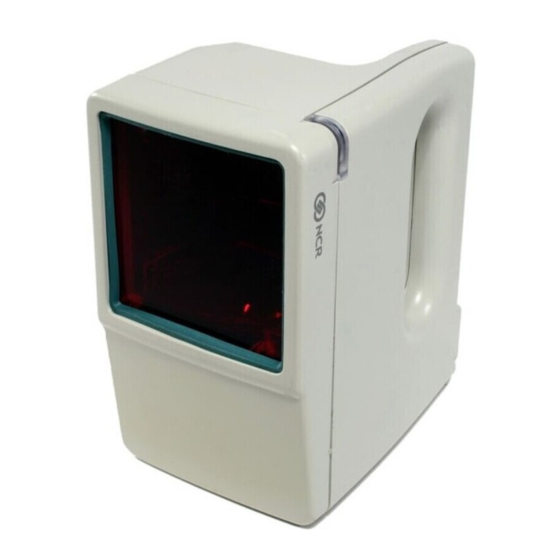
This eliminates the need of moving the label past the scan window, reducing the amount of operator activity. The 7890 Presentation Scanner is a small, compact unit that weighs less than two pounds. Figure 1-1 shows the scanner, connecting cables, and power module. - Page 31 Operating Your 7890 Scanner The NCR 7890 Presentation Scanner Figure 1-1 NCR 7890 Presentation Scanner User’s Guide...
-
Page 32: Using Your Scanner
Operating Your 7890 Scanner The NCR 7890 Presentation Scanner Because your NCR 7890 scanner is a hands-free Using Your Scanner presentation type scanner, it is much easier to use in the retail environment. The scanner sits on the counter and you present the bar code label to the scanner. -
Page 33: Laser Scanning
After reading the information contained in the bar code, the 7890 sends the information to the host terminal or personal computer (PC). Interfaces available for transmitting information are OCIA NCR Long, OCIA NCR Short, OCIA Non-NCR, RS-232, and IBM 468x/469x. -
Page 34: Site Requirements For Your 7890 Scanner
Contents Chapter 2 Site Requirements for Your 7890 Scanner Understanding Your 7890 Scanner Requirements ..............2-1 Physical Considerations ........2-1 Environmental Considerations ......2-3 Power Considerations ..........2-4 Scanner Location ............ 2-4 User’s Guide... - Page 35 Contents User’s Guide...
-
Page 36: Understanding Your 7890 Scanner Requirements
Understanding Your 7890 Scanner Requirements Understanding Your 7890 Scanner Requirements Your 7890 Presentation Scanner is designed to operate within a wide environmental range. Being a small peripheral unit, it does not require any special wiring or mounting. Normally, its requirements are within those of the host terminal or PC. - Page 37 Site Requirements for Your 7890 Scanner Understanding Your 7890 Scanner Requirements Figure 2-1 7890 Physical Dimensions User’s Guide...
-
Page 38: Environmental Considerations
Understanding Your 7890 Scanner Requirements Your 7890 Presentation Scanner operates in all standard Environmental working environments. Temperature and humidity Considerations ranges permitted are greater when the 7890 is in storage or transit. The following table gives the various environmental requirements. Working Range Storage Range 50°F to 104°F... -
Page 39: Power Considerations
Site Requirements for Your 7890 Scanner Understanding Your 7890 Scanner Requirements Your 7890 Presentation Scanner operates on only 9 Power Considerations Vdc. It receives current through the Scanner Module Cable, from a power module that plugs into an electrical outlet. One of four power modules comes with your scanner, depending on the requirements you specify. - Page 40 Preparing for Installation ..........3-3 What is in the Box ..........3-3 Reporting a Damaged Scanner ......3-3 Interpreting the 7890 Product Number ....3-4 Identifying Scanner Module Cables ....3-4 Identifying Interface Cables ......... 3-5 Determining Scanner Location ......3-6 Identifying Available Kits ........
- Page 41 Contents User’s Guide...
-
Page 42: Installing Your 7890 Scanner
Installing Your 7890 Scanner Installing Your 7890 Scanner Installing Your 7890 Scanner This overview of the Installing Your 7890 Scanner is Overview intended to help you understand the steps necessary to install the scanner. It identifies each of the things you must consider to have a successful installation. - Page 43 Installing Your 7890 Scanner Installing Your 7890 Scanner Installing the 7890 Scanner involves connecting all the Installing the Scanner cables, making any program changes, and installing a Holder if one is being used. Perform this process as follows. Install the Scanner Module Cable.
-
Page 44: Preparing For Installation
There is also some information that is useful as you get ready to install the scanner. After you have unpacked the 7890 Scanner according to What is in the Box the instructions printed on the box, take inventory to assure that you have received all components. -
Page 45: Interpreting The 7890 Product Number
Installing Your 7890 Scanner Preparing for Installation Currently, there are two models of the 7890 Presentation Interpreting the 7890 Scanner that can be configured with one of four Product Number different Power Modules. Figure 3-1 shows the interpretation of the 7890 Product Number. -
Page 46: Identifying Interface Cables
Installing Your 7890 Scanner Preparing for Installation The following table identifies the interface cable Identifying Interface required for the different host connections that can be Cables made with 7890 Presentation Scanner Interface Cable Host Connection Interface Corporate ID No. 2122... -
Page 47: Determining Scanner Location
RS-232 Omni-Link RS-232 1416-C200-0004 Note: You can also interface your 7890 Scanner to other host terminals not shown in the previous list. You normally do this by using RS-232 communications through a keyboard wedge. Your application may also require a software wedge. -
Page 48: Identifying Available Kits
Installing Your 7890 Scanner Preparing for Installation Figure 3-2 Scanner Cables Although it is not necessary, a Holder is very useful for Identifying Available keeping the scanner from sliding around on the counter Kits top as you scan labels. There are four available Holder Kits: Cup Holder, Dish Holder, Hook Holder, and Combination (all three holders). - Page 49 Installing Your 7890 Scanner Preparing for Installation A Power Module for the electrical requirements you specified comes with the 7890 Scanner. However, replacement Power Modules are available. The following table identifies the kit number for each available kit. Kit Description...
-
Page 50: Determining The Communication Protocol
(7452 only) Two-Three Tag Firmware 7890-K511-V001 2123 Cable with Opto Isolator 7890-K617-V001 Before connecting your 7890 Scanner to a host terminal Determining the or PC, you must verify the communication protocol Communication being used. The 7890 comes from the factory programmed for OCIA NCR Short;... - Page 51 IBM 468x - Addr 4A 4 Beeps IBM 468x - Addr 4B (1520 Bar Code Reader) 5 Beeps RS-232 6 Beeps IBM 468x - Addr 4B (Hand Held Bar Code Reader) Remove power from the 7890 Scanner. End of procedure. 3-10 User’s Guide...
-
Page 52: Installing The Scanner
Installing Your 7890 Scanner Installing the Scanner Installing the Scanner The Interface Cable shipped with your 7890 Scanner connects directly to the host terminal or PC. Since the installation is different from one terminal to another, you need to refer to your terminal documentation for instructions about how to connect the Interface Cable. -
Page 53: Installing The Scanner
Power Module Cable to the box on the end of the Interface Cable. Plug the Power Module into an electrical outlet. When the 7890 Scanner receives power, the diagnostics checks various hardware components. If the scanner passes the diagnostic tests, it gives a "ready"... -
Page 54: Modifying The Scanner Program
Refer to Chapter 5, Programming Your 7890 Scanner and Appendix A, Programming Worksheets. If you have an NCR 7890 Presentation Scanner already programmed the way you want it to be, you can transfer that program to another 7890 Presentation Scanner using Clone Programming as described at the end of Chapter 5 of this book. - Page 55 Contents Chapter 4 Operating Your 7890 Scanner The 7890 Scanner Components ........4-1 Presentation Scanning ..........4-2 Pick-Up Scanning ............4-5 Label Orientation ............4-6 Scan Pattern Location ........... 4-6 Label Rotation ............4-7 Distance from Scanner .......... 4-8 Read Indicators ............. 4-9 Status Indicator ............
- Page 56 Contents User’s Guide...
-
Page 57: Operating Your 7890 Scanner
Operating Your 7890 Scanner The 7890 Scanner Components The 7890 Scanner Components Before using your 7890 Presentation Scanner, you need to be familiar with some of its components. Figure 4-1 shows the scanner and identifies some of the parts and features. -
Page 58: Presentation Scanning
Operating Your 7890 Scanner Presentation Scanning Presentation Scanning Presentation scanning is much different from that used at checkout stands, such as in grocery stores. In the checkout stand environment, normally large quantities of items must be scanned in a short amount time. - Page 59 Operating Your 7890 Scanner The 7890 Scanner Components Figure 4-2 Presentation Scanning (1 of 3) Position the bar code label completely within the red Laser Scan Pattern as indicated in Figure 4-3. Normally the bar code should be three to four inches from the scanner.
- Page 60 Operating Your 7890 Scanner The 7890 Scanner Components Move the bar code label away from the scanner as shown in Figure 4-4. The scanner is now ready to read another bar code label. After not detecting an item for a period of time, the laser light turns off. To read another bar code, simply perform these three steps again.
-
Page 61: Pick-Up Scanning
In these circumstances you can pick up the scanner and take it to the merchandise. The 7890 Scanner includes a handle so that you can easily pick the scanner up and hold it. Being light-weight, you can present the scanner to the merchandise with little effort. -
Page 62: Label Orientation
Operating Your 7890 Scanner Label Orientation Label Orientation Because your 7890 Scanner produces a dense, omnidirectional scan pattern, labels can be read from many different angles. In order for the scanner to read a label, the center 90% of Scan Pattern one scan line must cross the bar code. -
Page 63: Label Rotation
Operating Your 7890 Scanner Label Orientation Your 7890 Scanner can read labels that are presented in Label Rotation many different positions. As shown in Figure 4-6, you can present labels that are rotated left or right 30 degrees from center, up or down 30 degrees from center, and 360 degrees around center. -
Page 64: Distance From Scanner
Label Orientation For optimum reading, the distance that you must place Distance from the label from the 7890 Scanner depends on the density Scanner and height of the bar code. You can relate this to focusing a camera, where you change the focus setting based on how far away the object is. -
Page 65: Read Indicators
When using IBM 468x communications, the Status Indicator flashes red (group of nine flashes repeated at 3-second intervals) when the 7890 is offline. This can be caused if the IBM host terminal has not established communications with the 7890, the host terminal is not turned on, or the interface cable is not connected. -
Page 66: Indicator Functions
The details for programming the "Good Read Tone" are in Chapter 5, Programming Your 7890 Scanner. Your 7890 Scanner comes with the "Good Read Tone" enabled. As you move the bar code label into the scan pattern, Indicator Functions the scanner tells you if it is able to read the label. -
Page 67: Bar Code Quality
The ability of your 7890 Scanner to read bar code labels depends greatly on the quality of the label. Although the 7890 can often read bar codes that appear to be bad, it cannot read bar codes that are obstructed, defective, or damaged. - Page 68 Operating Your 7890 Scanner Bar Code Quality The readability of a label depends on variables such as sizing, placement, color, paper type, ink viscosity, and package coatings. The middle of a printing run can yield erroneous labels due to the many variants involved.
-
Page 69: Taking Care Of Your Scanner
Also, totally avoid abrasive scrubbing or excessive cleaning agents. Your 7890 Scanner is designed to provide you with long, trouble-free service. However, it is up to you to care for your scanner. The following list identifies things you should consider in taking care of your scanner. -
Page 70: Scanner Operation Summary
The scanner gives either a Good Read Indication or no 2 Observe the Read indication. A Good Read is indicated by the Status Indication Indicator going from green to red and then back to green. If the Good Read tone is enabled, the 7890 also beeps. 4-14 User’s Guide... - Page 71 Operating Your 7890 Scanner Scanner Operation Summary Good Read Indication Put merchandise on counter top and go to next item entry. End of this item entry. No Read Indication Examine the bar code label. If it appears to be good, remove any folds or obstructions and try to read it again.
-
Page 72: Overview - Programming Your Scanner
Contents Chapter 5 Programming Your 7890 Scanner Overview - Programming Your Scanner ....5-1 Preparing for Your Program ......... 5-1 Completing the Worksheets ......... 5-1 Entering Your Program .......... 5-2 Requirements ............5-2 Helps ............... 5-2 Suggestion .............. 5-2 Programming Considerations ........5-3 Programming Worksheets ........ - Page 73 Contents Restart Lockout Timer ......... 5-16 Active Time ............5-17 Multiplier .............. 5-17 Parameter Shortcuts ..........5-18 Sample Program ........... 5-18 Entering the Program .......... 5-19 Bar Codes - 1 ............... 5-22 Code 128 ..............5-22 UPC/EAN ............. 5-22 Parameter Shortcuts ..........5-25 Sample Program ...........
- Page 74 Contents Version Number ........... 5-57 Parameter Shortcuts ..........5-57 Sample Program ........... 5-58 Entering the Program ......... 5-59 Additional Bar Code Options ........5-66 UPC Number System Character ......5-66 Sample Program ........... 5-66 Entering the Program .......... 5-67 RS-232 Parameters - 1 ..........5-68 Baud Rate ..............
- Page 75 Data ................ 5-89 Retries on IBM Message ........5-90 RS-232 Mode: Normal or Eavesdrop ....5-90 RS-232 Delay ............5-91 OCIA NCR Short Soft Rest ........5-91 Sample Program ........... 5-92 Entering the Program ........... 5-93 Clone Programming ........... 5-95 Scanner Programming Summary ......
-
Page 76: Preparing For Your Program
Programming Your 7890 Scanner Overview Overview This overview of programming your 7890 Scanner is intended to get you acquainted with the overall programming procedure. The Scanner Programming Summary at the end of this chapter is most useful after you have performed the programming function. -
Page 77: Entering Your Program
Program Enter the Base Programming state by scanning the Programming Mode tag; first tag after applying power to the 7890 Scanner. Select a Programming Worksheet and enter it’s parameter data by scanning the Hex tags identified in Your Program at the bottom of the Programming Worksheet. -
Page 78: Programming Considerations
The Programming Worksheets (refer to Appendix A) are Programming the focal point for writing a 7890 Scanner program. The Worksheets worksheets contain parameters that you select for your specific needs. The information is presented in a logical sequence, making it easy for you to select the required parameters. - Page 79 Tone - Four quick beeps from low to high frequency This tag puts the 7890 Scanner in the Short beep - good read Programming Base Programming state. It must be Mode...
-
Page 80: Programming Mode
Example: Hex D is 3 sets of 4 short beeps followed by 1 longer beep. To program your 7890 Scanner, it must be in the Programming Mode Programming Mode. Enter this mode by scanning the Programming Mode tag immediately after applying power to the scanner;... - Page 81 Hex tag. If you do not know how your 7890 Scanner is programmed, you can set it to all defaults, then enter any required changes to match your program. Do this by scanning the Default tag as the first tag after applying power to the scanner.
-
Page 82: Entering Your Program
Programming Your 7890 Scanner Entering Your Program Entering Your Program Entering your program consists of putting the 7890 Scanner in the Base Programming state, entering the parameter data on the Programming Worksheets, and saving the program. Use the following procedure to enter your program. -
Page 83: Communications Protocol
Communications Protocol Communications Protocol The Communications Protocol Programming mode selects the protocol that the 7890 Scanner uses to communicate with the host terminal or PC. Refer to the Communications Protocol worksheet in Appendix A. The Protocol parameter contains seven selections:... -
Page 84: Sample Program
Programming Your 7890 Scanner Communications Protocol Figure 5-1 shows an example of a completed Sample Program Communications Protocol Worksheet. In this example, RS-232 is the selected protocol. Figure 5-1 Communications Protocol Worksheet Example Your Program Refer to Program Entry on Page A-2... - Page 85 Programming Your 7890 Scanner Communications Protocol Note: You may need to change the setting of the Interface Switch. Refer to Chapter 6, Troubleshooting Your 7890 Scanner. The factory ships the 7890 Scanner with the Interface Switch set for OCIA. 5-10 User’s Guide...
-
Page 86: Good Read Tone
1250 Hertz. Select these frequencies using the Hex 0 through Hex 7 tags. The default frequency is 617 Hertz for the 7890 0100 model and 775 Hertz for the 7890 0200 model. Since most people cannot determine how a tone sounds based upon knowing its frequency, you can set the Tone Frequency by listening to it. -
Page 87: Tone Length
250 milliseconds. Select these times using the Hex 0 through Hex 9 tags. The default length is 150 milliseconds for the 7890 0100 model and 75 milliseconds for the 7890 0200 model. As with tone frequency, most people cannot identify short time lengths such as those available for Good Read Tones. -
Page 88: Sample Program
Programming Your 7890 Scanner Good Read Tone Figure 5-2 shows an example of a completed Good Read Sample Program Tone Programming worksheet. In this example the Good Read tone is programmed for the following. The tone sounds with each valid read. - Page 89 Programming Your 7890 Scanner Good Read Tone Enter all Parameters In the Base Programming state, scan the Hex 1 tag two times. Scan the Hex 0 tag to turn off the Good Read Tone or the Hex 1 tag to turn on the Good Read Tone.
- Page 90 Programming Your 7890 Scanner Good Read Tone Enter Specific Parameters In the Base Programming state, scan the Hex 1 tag two times. Scan the shortcut Hex tag (Hex A, Hex B, or Hex C) for the parameter you are changing.
- Page 91 Programming Your 7890 Scanner Good Read Tone Set the Tone Length by scanning the appropriate Hex tag or by repeatedly scanning the Hex A tag until you hear the desired tone length. If you used the Hex A tag, scan the END tag.
-
Page 92: Timers
Programming Your 7890 Scanner Timers Timers The Timers Programming mode controls the two 7890 Scanner timers: Lockout Time and Active Time. Refer to the Timers worksheet in Appendix A. The Lockout Timer prevents the scanner from Lockout Time repeatedly reading the same bar code. After reading a... -
Page 93: Active Time
Programming Your 7890 Scanner Timers You can program specific lengths of time that your 7890 Active Time scanner stays on after the last good read. You normally want to pick a time that is long enough for the operator to pick-up and scan the next item of a sale. However, remember that you also want to minimize the amount of time the laser is on. -
Page 94: Parameter Shortcuts
Programming Your 7890 Scanner Timers The Timers Programming mode contains four shortcuts: Parameter Shortcuts A, B, C, and D. After entering this programming mode you can go directly to a specific parameter by scanning the appropriate shortcut Hex tag (Hex A, Hex B, Hex C, and Hex D). -
Page 95: Entering The Program
Programming Your 7890 Scanner Timers You can enter the Timers parameters in one of two Entering the ways. One is to enter all parameters, the other is to Program enter specific parameters using parameter shortcuts. Enter all Parameters In the Base Programming state, scan the Hex 1 tag followed by the Hex 2 tag. - Page 96 Programming Your 7890 Scanner Timers Enter Specific Parameters In the Base Programming state, scan the Hex 1 followed by the Hex 2 tag. Scan the shortcut Hex tag (Hex A through Hex D) for the parameter you are changing. Which tag did you scan? Hex A Continue to step 3.
- Page 97 Programming Your 7890 Scanner Timers Enter the Active Time by scanning the appropriate Hex tag (Hex 0 through Hex 5). End of this procedure - program returns to Base Programming state (long then short beep). To disable the Multiplier , scan the Hex 0 tag, scan the Hex 1 tag to enable the Multiplier.
-
Page 98: Bar Codes - 1
Programming Your 7890 Scanner Bar Codes - 1 Bar Codes - 1 The Bar Codes - 1 Programming mode contains programming parameters for Code 128 and UPC/EAN bar codes. Refer to the Bar Codes - 1 worksheet in Appendix A. - Page 99 None, D-1, D-2, D-3, D-4, and D-5. Scan the appropriate Hex 0 through Hex 5 tag to input this parameter. The default is D-3 for the 7890 0100 model and None for the 7890 0200 model. Scanning a valid Hex tag ends the input for this parameter option.
- Page 100 Hex 0 tag also causes the scanner to go back to the Base Programming state. However, if you enable Periodical Codes, you must program the following parameters. Periodical Code Extension(7890 0200 model) The Periodical Code Extension parameter option has three selections: 2-digit extension only, 5-digit extension only or either 2- or 5-digit extensions.
-
Page 101: Parameter Shortcuts
Figure 5-4 shows an example of a completed Bar Codes Sample Program - 1 Programming worksheet for a 7890 0200 model. In this example the Code 128 and UPC/EAN bar codes are programmed for the following. -
Page 102: Entering The Program
Programming Your 7890 Scanner Bar Codes - 1 Figure 5-4 Bar Code - 1 Worksheet Example You can enter the Bar Codes - 1 parameters in one of Entering the two ways. One is to enter all the parameters in the Bar... - Page 103 Programming Your 7890 Scanner Bar Codes - 1 To disable reading UPC/EAN bar codes, scan the Hex 0 tag, scan the Hex 1 tag to enable reading UPC/EAN bar codes. Did you scan the Hex 0 tag or the Hex 1 tag?
- Page 104 Programming Your 7890 Scanner Bar Codes - 1 To disable Periodical Codes, scan the Hex 0 tag, scan the Hex 1 tag to enable Periodical Codes. Did you scan the Hex 0 tag or the Hex 1 tag? Hex 0...
- Page 105 Programming Your 7890 Scanner Bar Codes - 1 Enter Specific Parameters In the Base Programming state, scan the Hex 1 tag followed by the Hex 3 tag. Scan the shortcut Hex tag (Hex A through Hex F) for the parameter you are changing.
- Page 106 Programming Your 7890 Scanner Bar Codes - 1 To disable reading UPC/EAN bar codes, scan the Hex 0 tag, scan the Hex 1 tag to enable reading UPC/EAN bar codes. End of this procedure - program returns to Base Programming state (long then short beep).
- Page 107 Programming Your 7890 Scanner Bar Codes - 1 To disable Periodical Codes, scan the Hex 0 tag, scan the Hex 1 tag to enable Periodical Codes. End of this procedure - program returns to Base Programming state (long then short beep).
-
Page 108: Bar Code -
Programming Your 7890 Scanner Bar Codes - 2 Bar Codes - 2 The Bar Codes - 2 Programming mode contains programming parameters for Code 39. Refer to the Bar Codes - 2 worksheet in Appendix A. The Code 39 parameter controls reading Code 39 bar Code 39 codes. -
Page 109: Parameter Shortcuts
Programming Your 7890 Scanner Bar Codes - 2 Full ASCII Code 39 permits full ASCII capability by encoding the additional characters. Disable this function by scanning the Hex 0 tag, scan the Hex 1 tag to enable the function. Disable is the default. -
Page 110: Sample Program
Programming Your 7890 Scanner Bar Codes - 2 parameter by scanning the appropriate shortcut Hex tag (Hex A through Hex F). This eliminates the need to enter all parameters when only one needs changing. Figure 5-5 shows an example of a completed Bar Codes Sample Program - 2 Programming worksheet. -
Page 111: Entering The Program
Programming Your 7890 Scanner Bar Codes - 2 You can enter the Bar Codes - 2 parameters in one of Entering the two ways. One is to enter all the parameters in the Bar Program Codes - 2 Programming mode, the other is to enter only specific parameters by using parameter shortcuts. - Page 112 Programming Your 7890 Scanner Bar Codes - 2 Scan the Hex 0 tag to disable the Check Digit Present option, or the Hex 1 tag to enable it. Did you scan the Hex 0 tag or the Hex 1 tag?
- Page 113 Programming Your 7890 Scanner Bar Codes - 2 Enter Specific Parameters In the Base Programming state, scan the Hex 1 tag followed by the Hex 4 tag. Scan the shortcut Hex tag (Hex A through Hex E) for the parameter you are changing.
- Page 114 Programming Your 7890 Scanner Bar Codes - 2 Scan the appropriate Hex tag (Hex 1 through Hex 7) to enter your selection for the Minimum Characters Allowed. End of this procedure - program returns to Base Programming state (long then short beep).
-
Page 115: Bar Code -
Programming Your 7890 Scanner Bar Codes - 3 Bar Codes - 3 The Bar Codes - 3 Programming mode contains programming parameters for Interleaved 2 of 5. Refer to the Bar Codes - 3 worksheet in Appendix A. The Interleaved 2 of 5 parameter controls reading Interleaved 2 of 5 Interleaved 2 of 5 bar codes. - Page 116 Programming Your 7890 Scanner Bar Codes - 3 Value 1 and Value 2 The Value 1 and Value 2 parameter options specify the valid Interleaved 2 of 5 bar code lengths. Use this option with the Bar Code Length parameter option described in the previous section.
-
Page 117: Sample Program
Programming Your 7890 Scanner Bar Codes - 3 Hex 1 tag to enable it. The default is to disable sending the check digit. The Bar Codes - 3 Programming mode contains 4 Parameter Shortcuts shortcuts: A through D. After entering this... -
Page 118: Entering The Program
Programming Your 7890 Scanner Bar Codes - 3 You can enter the Bar Codes - 3 parameters in one of Entering the two ways. One is to enter all the parameters in the Bar Program Codes - 3 Programming mode, the other is to enter only specific parameters by using parameter shortcuts. - Page 119 Programming Your 7890 Scanner Bar Codes - 3 Did you scan the Hex 0 tag or the Hex 1 tag? Continue to step 4. Continue to step 6. Enter Value 1 (Minimum Value) by scanning the two appropriate Hex tags (Hex 0 through Hex 5 for the first character and Hex 0 through Hex 9 for the second).
- Page 120 Programming Your 7890 Scanner Bar Codes - 3 Did you scan the Hex 0 tag or the Hex 1 tag? Continue to step 10. Continue to step 9. Scan the Hex 0 tag to disable the Transmit Check Digit option, or the Hex 1 tag to enable it.
- Page 121 Programming Your 7890 Scanner Bar Codes - 3 Scan the Hex 0 tag to disable reading Interleaved 2 of 5 bar codes, scan the Hex 1 tag to enable reading Interleaved 2 of 5 bar codes. End of this procedure - program returns to Base Programming state (long then short beep).
- Page 122 Programming Your 7890 Scanner Bar Codes - 3 Enter Value 1 (Minimum Value) by scanning the two appropriate Hex tags (Hex 0 through Hex 5 for the first character and Hex 0 through Hex 9 for the second). Enter Value 2 (Maximum Value) by scanning the...
-
Page 123: Bar Codes - 4
Programming Your 7890 Scanner Bar Codes - 4 Bar Codes - 4 The Bar Codes - 4 Programming mode contains programming parameters for Code 128 bar codes. Refer to the Bar Codes - 4 worksheet in Appendix A. Older versions of the firmware do not include this programming mode. -
Page 124: Parameter Shortcuts
Programming Your 7890 Scanner Bar Codes - 4 The UCC 128 option refers to the Uniform Code Council UCC 128 Code 128 Data Formatter Start Code. Scan the Hex 0 tag to disable this function, or the Hex 1 tag to enable it. -
Page 125: Sample Program
Programming Your 7890 Scanner Bar Codes - 4 Figure 5-7 shows an example of a completed Bar Sample Program Codes - 4 Programming worksheet. In this example the Code 128 bar codes are programmed for the following. Code 128 enabled. -
Page 126: Entering The Program
Programming Your 7890 Scanner Bar Codes - 4 You can enter the Bar Codes - 4 parameters in one of Entering the two ways. One is to enter all the parameters in the Bar Program Codes - 4 Programming mode, the other is to enter only specific parameters by using parameter shortcuts. - Page 127 Programming Your 7890 Scanner Bar Codes - 4 Scan the shortcut Hex tag (Hex A, Hex B, or Hex C) for the parameter you are changing. Which tag did you scan? Continue to step 3. Continue to step 4. Continue to step 5.
-
Page 128: Label Identifiers
Appendix A. With older versions of the firmware, changes to the label identifiers for OCIA NCR Long are restricted to UPC-D bar codes only. Also, the only changes you can make are the Identifier Type and the Unique Identifier;... - Page 129 Programming Your 7890 Scanner Label Identifiers Default Prefix and Default Suffix Scan the Hex 0 tag to use the default prefix and the Hex 1 tag to use the default suffix. The default label identifiers vary depending on the type of bar code read.
- Page 130 Programming Your 7890 Scanner Label Identifiers Figure 5-8 Unique Label Identifier Formats User’s Guide 5-55...
-
Page 131: Bar Code Type
Programming Your 7890 Scanner Label Identifiers The Common Byte 1 and Common Byte 2 parameters Common Byte 1 and permit you to specify the data sent to the host terminal Common Byte 2 or PC in the Common Byte fields. Input this information as two Hex characters for each Common Byte. -
Page 132: Unique Identifier
Programming Your 7890 Scanner Label Identifiers The Common Byte parameter selects which common Common Byte bytes, if any, to add to the bar code data message. Each entry is unique to the previously specified Bar Code Type. Scan the Hex 0 tag for no Common Bytes, the... -
Page 133: Version Number
Programming Your 7890 Scanner Label Identifiers The Version Number parameter can be used only if you Version Number specified UPC-D as the bar code type. To include the Version Number in ASCII, scan the Hex 1 tag. Scan the Hex 0 tag if you do not want to include the Version Number. -
Page 134: Sample Program
Programming Your 7890 Scanner Label Identifiers Figure 5-9 shows an example of a completed Label Sample Program Identifiers Programming worksheet. This example shows the following programmed selections. Unique Identifier added to the front of all bar code data messages. Common Byte 1 is 5B ([). -
Page 135: Entering The Program
Programming Your 7890 Scanner Label Identifiers Figure 5-9 Label Identifiers Worksheet Example You can enter the Label Identifiers parameters in one of Entering the two ways. One is to enter all the parameters in the Label Program Identifiers Programming mode, the other is to enter only specific parameters by using parameter shortcuts. - Page 136 Programming Your 7890 Scanner Label Identifiers Enter all Parameters In the Base Programming state, scan the Hex 1 tag followed by the Hex 6 tag. Scan the appropriate Hex tag to select the Identifier Type. If you select Default Prefix (Hex 0), Default Suffix (Hex 1), or None (Hex 2) you do not enter any other parameters.
- Page 137 Programming Your 7890 Scanner Label Identifiers character and Hex 0 through Hex F for the second). If you are not using Common Byte 2, scan any two Hex tags except Hex 0 or the Terminator Byte value. Tone sounds two long beeps.
- Page 138 Programming Your 7890 Scanner Label Identifiers Return to step 5. Continue to step 10. Scan the End tag to exit this programming mode. End of this procedure - program returns to Base Programming state (long then short beep). User’s Guide...
- Page 139 Programming Your 7890 Scanner Label Identifiers Enter Specific Parameters In the Base Programming state, scan the Hex 1 tag followed by the Hex 6 tag. Scan the shortcut Hex tag (Hex A through Hex D) for the parameter you are changing.
- Page 140 Programming Your 7890 Scanner Label Identifiers Enter Common Byte 1 by scanning the appropriate two Hex tags (Hex 0 through Hex 7 for the first character and Hex 0 through Hex F for the second). End of this procedure - program returns to Base Programming state (long then short beep).
- Page 141 Programming Your 7890 Scanner Label Identifiers Enter the Unique Identifier for the Bar Code Type just selected in step 6. Do this by scanning the appropriate two Hex tags (Hex 0 through Hex 7 for the first character and Hex 0 through Hex F for the second).
-
Page 142: Additional Bar Code Options
UPC Number System Character. Refer to the Additional Bar Code Options worksheet in Appendix A. This parameter determines whether the 7890 should UPC Number System include the UPC Number System Character with the Character UPC data. -
Page 143: Entering The Program
Programming Your 7890 Scanner Additional Bar Code Options Figure 5-10 Additional Bar Code Options Worksheet Example You can enter this Additional Bar Code Options Entering the parameter in only one way. The firmware accepts the Program option change and then returns to the base programming state. -
Page 144: Rs-232 Parameters - 1
Programming Your 7890 Scanner RS-232 Parameters - 1 RS-232 Parameters - 1 The RS-232 Parameters - 1 Programming mode contains four of the parameters required for RS-232 communications. From this programming mode you can select the Baud Rate, Parity, Stop Bits And Character Length, and Handshake Options. -
Page 145: Handshake
Programming Your 7890 Scanner RS-232 Parameters - 1 tag to set the Stop Bits And Character Length. The default is 1 Stop Bit and 7-Bit Character length. The Handshake parameter contains six selections. Handshake When considering these, note that the scanner controls only RTS, it can monitor CTS. -
Page 146: Parameter Shortcuts
Programming Your 7890 Scanner RS-232 Parameters - 1 The RS-232 Parameters - 1 Programming mode contains Parameter Shortcuts four shortcuts: A, B, C, and D. After entering this programming mode you can go directly to a specific parameter by scanning the appropriate shortcut Hex tag (Hex A through Hex D). -
Page 147: Entering The Program
Programming Your 7890 Scanner RS-232 Parameters - 1 You can enter the RS-232 Parameters - 1 program Entering the parameters in one of two ways. One is to enter all the Program parameters, the other is to enter only specific parameters by using parameter shortcuts. - Page 148 Programming Your 7890 Scanner RS-232 Parameters - 1 Enter Specific Parameters In the Base Programming state, scan the Hex 2 tag followed by the Hex 0 tag. Scan the shortcut Hex tag (Hex A through Hex D) for the parameter you are changing.
- Page 149 Programming Your 7890 Scanner RS-232 Parameters - 1 Select the number of Stop Bits and the Character Length by scanning the appropriate Hex tag (Hex 0 through Hex 3). End of this procedure - program returns to Base Programming state (long then short beep).
-
Page 150: Rs-232 Parameters - 2
Programming Your 7890 Scanner RS-232 Parameters - 2 RS-232 Parameters - 2 The RS-232 Parameters - 2 Programming mode contains some of the parameters required for RS-232 communications. From this mode you can select BCC Options, Interface Control, Check Digit, VLI And Bit 6 EOM, and Retransmit On ACK Timer Expiration. -
Page 151: Check Digit
Programming Your 7890 Scanner RS-232 Parameters - 2 An XOff message does not permit the transmission of data until the scanner receives an XOn message. An XOff message can be received any time. If the scanner is sending a message when it receives an XOff, data transmission stops after sending the current byte. -
Page 152: Retransmit On Ack/Nak Timer Expiration
Programming Your 7890 Scanner RS-232 Parameters - 2 Bit 6 EOM identifies the end of a data message. If you select this option, Bit 6 of the last byte in the message determines the end of the message. Scan the appropriate Hex 0 through Hex 3 tags to enable or disable VLI and Bit 6 EOM. -
Page 153: Sample Program
Programming Your 7890 Scanner RS-232 Parameters - 2 Figure 5-12 shows an example of a completed RS-232 Sample Program Parameters - 2 programming worksheet. This example shows the following program selections. BCC Option enabled Interface Control is for ACK/NAK Check Digit programmed to enable UPC-A, UPC-E,... -
Page 154: Entering The Program
Programming Your 7890 Scanner RS-232 Parameters - 2 You can enter the RS-232 Parameters - 2 programming Entering the parameters in one of two ways. One is to enter all the Program parameters, the other is to enter only specific parameters by using parameter shortcuts. - Page 155 Programming Your 7890 Scanner RS-232 Parameters - 2 Enter Specific Parameters In the Base Programming state, scan the Hex 2 tag followed by the Hex 1 tag. Scan the shortcut Hex tag (Hex A through Hex E) for the parameter you are changing.
- Page 156 Programming Your 7890 Scanner RS-232 Parameters - 2 Select the Interface Control by scanning the appropriate Hex tag (Hex 0 through Hex 3). End of this procedure - program returns to Base Programming state (long then short beep). Select the Check Digit option by scanning the appropriate Hex tag (Hex 0 through Hex 3).
-
Page 157: Rs-232 Prefix Byte
Programming Your 7890 Scanner RS-232 Prefix Byte RS-232 Prefix Byte The RS-232 Prefix Byte Programming mode controls the use of prefix bytes. If you use an RS-232 Prefix Byte, it is the leading character in each message sent to the host terminal or PC. -
Page 158: Sample Program
Programming Your 7890 Scanner RS-232 Prefix Byte Figure 5-13 shows an example of a completed RS-232 Sample Program Prefix Byte programming worksheet. This example shows the Prefix Byte enabled, and ASCII code STX (02 Hex) transmitted as the leading character of each message sent to the host terminal or PC. - Page 159 Programming Your 7890 Scanner RS-232 Prefix Byte Enter all Parameters In the Base Programming state, scan the Hex 2 tag two times to enter the RS-232 Prefix Byte Programming mode. Scan the Hex 0 tag to disable the Prefix Byte, or the Hex 1 tag to enable it.
- Page 160 Programming Your 7890 Scanner RS-232 Prefix Byte Enter Specific Parameters In the Base Programming state, scan the Hex 2 tag two times. Scan the shortcut Hex tag (Hex A or Hex B) for the parameter you are changing. Which tag did you scan? Continue to step 3.
-
Page 161: Rs-232 Terminator Byte
Programming Your 7890 Scanner RS-232 Terminator Byte RS-232 Terminator Byte The RS-232 Terminator Byte Programming mode controls the use of terminator bytes. If you use an RS- 232 Terminator Byte, it goes at the end of the message sent to the host terminal or PC. If you included a BCC... -
Page 162: Parameter Shortcuts
Programming Your 7890 Scanner RS-232 Terminator Byte The RS-232 Terminator Byte Programming mode Parameter Shortcuts contains 2 shortcuts: A and B. After entering this programming mode you can go directly to a specific parameter by scanning the appropriate shortcut Hex tag (Hex A or Hex B). - Page 163 Programming Your 7890 Scanner RS-232 Terminator Byte Enter all Parameters In the Base Programming state, scan the Hex 2 tag followed by the Hex 3 tag to enter the RS-232 Terminator Byte Programming mode. Scan the Hex 0 tag to disable the Terminator Byte, or the Hex 1 Hex tag to enable it.
- Page 164 Programming Your 7890 Scanner RS-232 Terminator Byte Enter Specific Parameters In the Base Programming state, scan the Hex 2 tag followed by the Hex 3 tag. Scan the shortcut Hex tag (Hex A or Hex B) for the parameter you are changing.
-
Page 165: Communications Options
OCIA Tag Message have the scanner just drop the data after one to two seconds. If you scan the Hex 2 tag, the NCR 7890 Data Scanner holds or maintains the OCIA tag data. If you scan the Hex 3 tag, the scanner drops the data after one to two seconds. -
Page 166: Retries On Ibm Message
When using this mode a special cable is required. Data transmitted by the terminal is sent to the 7890 and re-transmitted to the host. Data from the host is sent to the "dumb CRT". -
Page 167: Rs-232 Delay
50-millisecond delay. Selecting the proper delay can assure that all tag data is received by the host. The default is 0 milliseconds for the 7890 0100 model and 10 milliseconds for the 7890 0200 model. This program parameter allows the 7890 Scanner to... -
Page 168: Sample Program
Programming Your 7890 Scanner Communications Options Figure 5-15 shows an example of a completed Sample Program Communications Options programming worksheet. This example shows the following programming selections. Send IBM Tags in Hex Maintain OCIA Taga Message Data Unlimited retries on IBM Message... -
Page 169: Entering The Program
Programming Your 7890 Scanner Communications Options You can enter these Communications Options Entering the parameters only one at a time. With this group of Program parameters the firmware accepts one option change and returns to the base programming state. To program another parameter you must scan the Hex 2 and Hex 4 tags again. - Page 170 Programming Your 7890 Scanner Communications Options Scan either the Hex 0 tag to send IBM tags in Hex, scan the Hex 1 tag to send IBM tags in ASCII. End of this procedure - program returns to Base Programming state (long then short beep).
-
Page 171: Clone Programming
7890 Presentation Scanner (transmitter) to another (receiver) without using connecting cables. Thus, you can enter a program in one 7890 scanner, and then quickly and easily copy it to other 7890 scanners. The following steps identify how to use the Clone Programming feature. - Page 172 To clone another scanner, repeat the above steps starting at step 2. Note: The Clone Programming feature is cross- compatible between the 7890-0100 and 7890-0200 models as long as the receiving scanner’s firmware supports the features to be cloned. User’s Guide...
-
Page 173: Scanner Programming Summary
Scanner Programming Summary Scanner Programming Summary This is a summary description of how to program your 7890 Presentation Scanner. Use this summary along with the information contained in this chapter. Creating the program Identify your requirements Determine the requirements of your program. This... - Page 174 Programming Your 7890 Scanner Scanner Programming Summary Entering the Program Prepare the 7890 Presentation Scanner Apply power to the 7890 Scanner, then scan the Programming Mode tag. This puts the scanner in the Base Programming state. Select the specific programming mode Scan the two Hex tags for a specific programming mode, then enter all the parameter data for it.
-
Page 175: Saving The Program
Programming Your 7890 Scanner Scanner Programming Summary Saving the Program Scan the Save and Reset tag When you scan the Save and Reset Tag, the scanner saves all programming parameters that you entered. This becomes the new scanner program. The scanner goes through initial start-up and operates using the new program. - Page 176 Programming Your 7890 Scanner Scanner Programming Summary User’s Guide 5-101...
- Page 177 Contents Chapter 6 Troubleshooting Your 7890 Scanner Fault Identification ............6-1 Repairing Your 7890 Scanner ........6-4 Interface Switch ............6-5 Switch Function ............6-5 Changing the Interface Switch Setting ....6-6 Fuse ................6-7 User’s Guide...
- Page 178 Contents User’s Guide...
-
Page 179: Fault Identification
If your 7890 scanner does not work properly, you might be able to determine the problem and correct it without having to send the scanner in for repair. Use the following steps to help isolate the problem. - Page 180 Troubleshooting Your 7890 Scanner Fault Identification Problem Status Tone Possible Cause Corrective Action Indicator Scanner does not No power to the Check the electrical operate. unit. outlet for proper power. Laser light off Check all cables for Motors off being connected Interface Cable properly.
- Page 181 (103 vs 104 vs 106). Scanner does not Rapidly None Host terminal Terminal should enable operate when flashes has sent the 7890 the 7890 later in the using IBM 468x a command to transaction. communications. prevent it from reading bar codes. User’s Guide...
-
Page 182: Repairing Your 7890 Scanner
The illustration on the top flap of the box shows how to pack your scanner in the box. Send only the 7890 Scanner, do not include the Power Module, Scanner Module Cable, and Interface Cable. Also, include a description of the problem; be as specific and complete as possible. -
Page 183: Interface Switch
Troubleshooting Your 7890 Scanner Interface Switch Interface Switch The 7890 Scanner includes circuitry for all available interface options. However, the interface switch must match the communication protocol programming. The interface switch selects the active interface by Switch Function selecting the circuits to the Interface Connector. To change between OCIA and RS-232 or IBM 468x, you must change the setting of the interface switch. -
Page 184: Changing The Interface Switch Setting
Troubleshooting Your 7890 Scanner Interface Switch Be sure to disconnect the cable from the scanner before Changing the changing the Interface Switch setting. You access the Interface Switch Interface Switch by inserting a paper clip through a hole in the cabinet, close to the cable connector. Activate the... -
Page 185: Fuse
Troubleshooting Your 7890 Scanner Fuse Fuse Your 7890 Presentation Scanner does not contain a fuse inside the cabinet. However, there is a fuse in the connector box on the end of the Interface Cable. The green light on the connector box should be on if the Power Module is plugged into the proper electrical outlet and is connected to the. -
Page 186: Overview - Programming Worksheets
Contents Appendix A Programming Worksheets Overview - Programming Worksheets ...... A-1 Purpose ..............A-1 Format ..............A-1 Defaults ..............A-1 Shortcuts ..............A-2 ASCII Characters ........... A-2 Program Entry ............A-2 User’s Guide... - Page 187 Contents User’s Guide...
-
Page 188: Purpose
7890 0100 and 7890 0200 models are the same. Scanning the Default tag as the first tag after applying power to the 7890 sets the parameters to these values. The Defaults table lists all the default values. -
Page 189: Shortcuts
Some host terminals can corrupt your program if they Program Entry are running and are connected to the 7890 while you are entering a program. Either turn the host terminal off or disconnect the interface cable from the host terminal before entering your program. - Page 190 Data as Decoded Bar Codes - 2 Code 39 Enable Minimum Characters Allowed Full ASCII Disable Check Digit Present Disable Transmit Check Digit Disable Allow Single Character Tags Disable * Program Parameter only available for 7890 0200 model. User’s Guide...
- Page 191 Programming Worksheets Overview DEFAULTS Bar Codes - 3 Interleaved 2 of 5 Enable Bar Code Length Range Check Value 1 Value 2 Check Digit Present Disable Transmit Check Digit Disable Bar Codes - 4 Code 128 Enable Minimum Data Characters UCC 128 Disable Label Identifiers...
- Page 192 Send IBM Tags in Hex or ASCII Maintain or Drop OCIA Tag Data Maintain Retries on IBM Messages Unlimited RS-232 Mode: Normal, Eavesdrop Normal RS-232 Delay (7890 0100) 0 Milliseconds RS-232 Delay (7890 0200) 10 Milliseconds OCIA NCR Short Soft Reset Parity User’s Guide...
- Page 193 Programming Worksheets Overview User’s Guide...
- Page 194 Programming Worksheets Overview User’s Guide...
- Page 195 Programming Worksheets Overview User’s Guide...
- Page 196 Programming Worksheets Overview User’s Guide...
- Page 197 Programming Worksheets Overview A-10 User’s Guide...
- Page 198 Programming Worksheets Overview User’s Guide A-11...
- Page 199 Programming Worksheets Overview A-12 User’s Guide...
- Page 200 Programming Worksheets Overview User’s Guide A-13...
- Page 201 Programming Worksheets Overview A-14 User’s Guide...
- Page 202 Programming Worksheets Overview User’s Guide A-15...
- Page 203 Programming Worksheets Overview A-16 User’s Guide...
- Page 204 Programming Worksheets Overview User’s Guide A-17...
- Page 205 Programming Worksheets Overview A-18 User’s Guide...
- Page 206 Programming Worksheets Overview User’s Guide A-19...
- Page 207 Programming Worksheets Overview A-20 User’s Guide...
- Page 208 Index Additional Bar Code Options Programming Information, 5-66 Programming Worksheet, A-14 ASCII Code Chart, A-20 Bar Code Quality, 4-12 Bar Codes - 1 Programming Information, 5-22 Programming Worksheet, A-9 Bar Codes - 2 Programming Information, 5-32 Programming Worksheet, A-10 Bar Codes - 3 Programming Information, 5-39 Programming Worksheet, A-11 Bar Codes - 4...
- Page 209 Programming Information, 5-89 Programming Worksheet, A-19 Communications Protocol Programming Information, 5-7 Programming Worksheet, A-6 Determining the Communication Protocol, 3-9 Components of 7890 Scanner, 4-1 Damaged Scanner, 3-3 Fuse, 6-7 Good Read Tone Programming Information, 5-10 Programming Worksheet, A-7 Holders Kit, 3-7...
- Page 210 Determining the Communication Protocol, 3-9 Identifying Available Kits, 3-7 Identifying Interface Cables, 3-5 Identifying Scanner Module Cables, 3-4 Installing the Scanner, 3-11 Interpreting the 7890 Product Number, 3-4 Modifying the Scanner Program, 3-13 Overview, 3-1 Preparing for, 3-3 Reporting a Damaged Scanner, 3-3...
- Page 211 Location for Scanner Installation, 2-4, 3-6 Maintenance, 4-14 Operation Label Orientation, 4-6 Pick-Up Scanning, 4-5 Presentation Scanning, 4-2 Summary, 4-15 Power Module Connecting the Power Module, 3-12 Identifying Available Kits, 3-7 Power Considerations, 2-4 Product Number Interpreting the 7890 Product Number, 3-4 User’s Guide...
- Page 212 Index Programming Bar Codes - 1, 5-22 Bar Codes - 2, 5-32 Bar Codes - 3, 5-39 Bar Codes - 4, 5-47 Clone Programming, 5-95 Communications Protocol, 5-7 Considerations, 5-3 Defaults, A-3 Entering Your Program, 5-6 Good Read Tone, 5-10 Label Identifiers, 5-52 Overview, 5-1, A-1 RS-232 Parameters - 1, 5-68...
- Page 213 Programming Worksheet, A-16 RS-232 Prefix Byte Programming Information, 5-81 Programming Worksheet, A-17 RS-232 Terminator Byte Programming Information, 5-85 Programming Worksheet, A-17 Scanner Care, 4-15 Scanner Introduction 7890 Presentation Scanner, 1-1 Laser Scanning, 1-4 Using Your Scanner, 1-3 Scanning Methods User’s Guide...
- Page 214 Site Requirements Dimensions, 2-2 Environmental Considerations, 2-3 Physical Considerations, 2-1 Power Considerations, 2-4 Scanner Location, 2-4 Timeouts Programming Information, 5-16 Programming Worksheet, A-8 Troubleshooting Fault Identification, 6-1 Fuse, 6-7 Repairing Your 7890 Scanner, 6-4 Window Assembly Kit, 3-7 User’s Guide...
- Page 215 Number: BD20-0901-A Issue: G Date: November 1998 NCR welcomes your feedback on this publication. Your comments can be of great value in helping us improve our information products. Circle the numbers below that best represent your opinion of this publication.
- Page 216 Fold NO POSTAGE NECESSARY IF MAILED IN THE UNITED STATES BUSINESS REPLY MAIL FIRST CLASS PERMIT NO. 3 DAYTON, OHIO POSTAGE WILL BE PAID BY ADDRESSEE NCR CORPORATION RETAIL SYSTEMS GROUP INFORMATION PRODUCTS DEPT 2651 SATELLITE BLVD. DULUTH, GA 30136...
- Page 217 Printed on recycled paper BD20-0901-A November 1998...
Need help?
Do you have a question about the 7890 and is the answer not in the manual?
Questions and answers