Table of Contents
Advertisement
Quick Links
Advertisement
Table of Contents
Troubleshooting

Subscribe to Our Youtube Channel
Related Manuals for NCR RealScan 7837-3000


Summary of Contents for NCR RealScan 7837-3000
- Page 1 NCR RealScan 7837‐3000 Release 1.0 User Guide B005‐0000‐1610 Issue B ...
- Page 2 The product described in this book is a licensed product of NCR Corporation. NCR is a registered trademark of NCR Corporation. NCR RealScan is a trademark of NCR Corporation in the United States and/or other countries. It is the policy of NCR Corporation (NCR) to improve products as new technology, components, software, and firmware become available. NCR, therefore, reserves the right to change specifications without prior notice. All features, functions, and operations described herein may not be marketed by NCR in all parts of the world. In some instances, photographs are of equipment prototypes. Therefore, before using this document, consult with your NCR representative or NCR office for information that is applicable and current. To maintain the quality of our publications, we need your comments on the accuracy, clarity, organization, and value of this book. Address correspondence to: Manager, Information Products NCR Corporation 2651 Satellite Blvd. Duluth, GA 30096 Copyright © 2005 By NCR Corporation Dayton, Ohio U.S.A. All Rights Reserved ...
- Page 3 Preface Audience Notice: This document is NCR proprietary information and is not to be disclosed or reproduced without consent. ...
-
Page 4: Table Of Contents
Table of Contents Chapter 1: Getting Started NCR 5620 ....................1‐1 About This Manual................ 1‐2 Unpacking the System..............1‐2 Models ..................... 1‐3 About the Battery................1‐4 Charging Information ............... 1‐4 Battery Recommendations ............1‐4 Proper Disposal of the Battery..........1‐5 Base Charge Mode ................. 1‐5 Linking Scanner to Base ..............1‐6 Unlinking the Scanner..............1‐7 Link Modes................. 1‐7 Locked Link Mode..............1‐7 Open Link Mode................ 1‐8 Out‐of‐Range Alarm..............1‐8 Duration .................. - Page 5 System Conditions..............1‐13 Connecting the Base When Powered by Host (Keyboard Wedge)................... 1‐14 Reading Techniques ..............1‐16 Resetting the Standard Product Defaults ......... 1‐17 Plug and Play................1‐17 Keyboard Wedge Connection ............ 1‐17 Laptop Direct Connect ..............1‐18 RS‐232 .................... 1‐18 Wand Emulation Plug & Play ............ 1‐19 IBM 4683 Ports 5B, 9B, and 17 Interface........1‐19 Connecting the Base with USB........... 1‐20 IBM SurePos ................. 1‐21 USB PC or Macintosh Keyboard..........1‐22 USB HID ..................1‐22 USB Com Port Emulation ............1‐22 CTS/RTS Emulation..............
- Page 6 Host ACK Selection ..............2‐12 Host ACK Enable ................. 2‐14 Base/Host Escape Commands............ 2‐14 Wand Emulation ................2‐15 Wand Emulation Connection ..........2‐15 Wand Emulation Transmission Rate ........2‐15 Wand Emulation Polarity............2‐16 Wand Emulation Idle .............. 2‐16 Wand Emulation Data Block Size ......... 2‐17 Wand Emulation Delay Between Blocks......2‐17 Wand Emulation Overall Checksum ........2‐17 Chapter 3: Output Good Read Indicators ................3‐1 Beeper – Good Read................ 3‐1 Beeper Volume – Good Read............3‐1 Beeper Pitch – Good Read ............3‐1 Beeper Duration – Good Read .............
- Page 7 Reread Delay .................. 3‐6 User‐Specified Reread Delay............3‐6 Centering Window ................ 3‐7 Output Sequence Overview ............3‐8 Require Output Sequence............3‐8 Output Sequence Editor ............3‐8 Output Sequence Editor ............3‐9 Require Output Sequence............3‐10 Output Sequence Example ............. 3‐10 Multiple Symbols ................. 3‐12 No Read..................3‐12 Video Reverse................3‐13 Chapter 4: Data Editiing Prefix/Suffix Overview ................ 4‐1 Points to Keep In Mind ..............4‐1 To Add a Prefix or Suffix: ............. 4‐2 To Clear One or All Prefixes or Suffixes: ........
- Page 8 Chapter 5: Data Formatting Data Format Editor Introduction ............5‐1 To Add a Data Format ................. 5‐2 Other Programming Selections ............5‐4 Data Format Editor Commands ............5‐5 Send Commands ................5‐5 Move Commands................5‐5 Search Commands ................. 5‐6 Miscellaneous Commands............5‐7 Data Format Editor ................ 5‐8 Data Formatter ................5‐8 Alternate Data Formats..............5‐9 Chapter 6: Symbologies Introduction................... 6‐1 All Symbologies ................6‐1 Message Length................6‐2 Codabar ................... 6‐2 Codabar ...................
- Page 9 Code 39 Code Page ................ 6‐8 Interleaved 2 of 5 ..............6‐8 Check Digit ..................6‐8 Interleaved 2 of 5 Message Length ..........6‐9 Code 93 .................... 6‐9 Code 93 ..................6‐10 Code 93 Message Length ............6‐10 Code 93 Code Page ..............6‐10 Code 2 of 5 ..................6‐11 Code 2 of 5 ..................6‐11 Code 2 of 5 Message Length............6‐11 IATA Code 2 of 5, continued ..........6‐11 IATA Code 2 of 5 Message Length ........6‐12 Matrix 2 of 5................
- Page 10 viii UPC‐A/EAN‐13 with Extended Coupon Code......6‐19 UPC E0 and UPC E1 ..............6‐19 UPC E0 and UPC E1 Expand ............. 6‐20 UPC E0 and UPC E1 Addenda Required ......... 6‐20 UPC E0 and UPC E1 Addenda Separator ........ 6‐20 UPC E0 Check Digit..............6‐20 UPC E0 Number System............. 6‐21 UPC E0 Addenda ................. 6‐21 EAN/JAN 13 Check Digit............6‐22 EAN/JAN 13 Addenda..............6‐22 EAN/JAN 13 Addenda Required..........6‐22 EAN/JAN 13 Addenda Separator..........6‐23 ISBN Translate................6‐24 EAN/JAN 8 Check Digit ............. 6‐24 EAN/JAN 8 Addenda..............6‐25 EAN/JAN 8 Addenda Required..........6‐25 EAN/JAN 8 Addenda Separator..........6‐25 MSI ....................
- Page 11 EAN UCC Emulation ..............6‐30 China Post Code................6‐30 China Post Message Length ............6‐31 Korea Post Code................6‐31 Korea Post Code................6‐31 Korea Post Message Length............6‐31 PosiCode A and B ................ 6‐32 PosiCode Message Length............6‐33 Trioptic Code ................6‐33 Codablock F Message Length ............ 6‐34 Code 16K ..................6‐34 Code 16K ..................6‐34 Code 16K Message Length ............6‐35 Code 49 ..................6‐35 Code 49 ..................6‐35 Code 49 Message Length ............
- Page 12 Menu Command Syntax ............. 10‐1 Query Commands................ 10‐2 Concatenation of Multiple Commands........10‐3 Responses..................10‐3 Examples of Query Commands..........10‐4 Trigger Commands..............10‐5 Resetting the Standard Product Defaults ......... 10‐5 Menu Commands ................ 10‐7 Chapter 11: Product Specifications NCR 7837 Product Specifications............. 11‐1 Base Station Product Specifications ..........11‐2 INCR 7837 Depth of Field ..............11‐3 Standard Cable Pinouts Keyboard Wedge ........11‐4 Standard Cable Pinouts Wand Emulation ........11‐5 Standard Cable Pinouts Serial Output ..........11‐6 Standard Cable Pinouts USB ............11‐7...
- Page 13 Chapter 12: Maintenance Maintenance.................. 12‐1 Cleaning the Scanner’s Window..........12‐1 Inspecting Cords and Connectors ..........12‐2 Replacing the Base Interface Cable..........12‐2 Changing the NCR 7837 Battery:..........12‐3 Troubleshooting Base ..............12‐3 Is the red LED on? ..............12‐3 Is the green LED on? ............... 12‐3 Troubleshooting Scanner ............12‐4 Is the scanner having trouble reading your symbols? ..12‐4 Is the bar code displayed but not entered into the application? ................12‐4 Does the scanner read the bar code incorrectly?....12‐4 The scanner does not read your bar code at all....12‐5 Troubleshooting the Cordless System ........12‐5 Appendix A: Symbology Chart................. A‐1 ASCII Conversion Chart (Code Page 1252) ........
- Page 14 Revision Record Issue Date Remarks A Nov 2004 First issue B Mar 2005 Added Troubleshooting in Appendix A Replaced faulty programming barcodes Safety and Regulatory Information The NCR RealScan 7832 conforms to all applicable legal requirements. To view the compliance statements see the NCR RealScan 7837 Regulatory Information – (B005‐0000‐1611). ...
-
Page 15: Ncr 5620
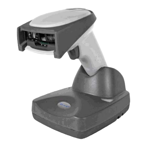
Getting Started Chapter 1: NCR 5620 The NCR 5620 cordless scanning system consists of a base and an NCR 7837 Cordless Linear Imager. The 7837 marks a new performance level for hand held scanners. The 7837 is powered by Adaptus Imaging Technology. The performance of Adaptus technology delivers aggressive read rates and depths of field on 1D codes. Designed for today’s demanding retail and commercial environments, the 7837 offers a superior reading range, durability, and the ability to read poor quality bar codes. Linear imaging technology is defined by a bright and sharply focused aiming line, high resolution imaging, and fast reading speed. The 7837 is comfortable to hold, easy to use, rugged, and excellent for retail applications, as well as for all general scanning applications. The cordless system is an economical, durable solution for a wide variety of portable data collection applications. The cordless system features: • a tough, ergonomic thermoplastic housing for comfort and durability. • an advanced two‐way spread‐spectrum radio, Bluetooth ® wireless technology • a wide range of interfaces: keyboard wedge, wand emulation, RS‐232 terminals, USB, and legacy decoders. • visible and audible feedback for confirmation of a successful decode. ... -
Page 16: About This Manual
Chapter 1: Getting Started • a rechargeable battery designed to operate through a whole work day. The cordless system can be programmed for many communication parameters and input/output protocols compatible to the host, as well as advanced data editing and formatting. About This Manual This manual contains information to help you set up, operate, and program the cordless system. Product specifications, connector pinouts, a troubleshooting guide, and customer support information are also provided. NCR bar code scanners are factory programmed for the most common terminal and communications settings. If you need to change these settings, programming is accomplished by scanning the bar codes in this guide. An asterisk (*) next to an option indicates the default setting. This section contains the following information: • Unpacking the System • Cordless System Main Components • Battery and Charging Information • Linking the Scanner to the Base • Beeper and LED Sequences and Their Meaning • Basic Operation of the Cordless System • Communication Between the Cordless System and the Host • Connection of the Base to an Interface Unpacking the System After you open the shipping carton containing the product, perform ... -
Page 17: Models
Chapter 1: Getting Started • Check to make sure everything you ordered is present. • Save the shipping container for later storage or shipping. • Check for damage during shipment. Report damage immediately to the carrier who delivered the carton. Models Models Description 7837‐3000 Cordless Linear Scanner with Base ... -
Page 18: About The Batte Ry
Chapter 1: Getting Started About the Batte Use only the Li‐ion battery packs provided by NCR. The use of any battery pack not sold by NCR voids your warran ty and may result in damage to your unit. Power is supplied to the cordless scanner by a rechargeable battery that is integrated in the scanner handle. Each scanner is shipped with a battery. Charging Info rmation The battery is designed to charge while the scanner is positione d in the cordless base unit. Refer to 7837 LED Sequences and Their Meaning fo r an interpretation of the Charge Status indicators. • Place the scanner in the bas e that is connected to an appropriate power supply. Battery Recommendations Batteries are shipped approximately 30% to 60% charged and shou ld be fully char ged for maximum charge capacity. The battery is a lithium ion cell and can be used without a full charge, as well as can be charged with out fully discharging, without impacting the battery life. There is no need to perform any charge/discharge conditioning on this cell type battery. Do not disassemble the battery. There are no user‐serviceable parts in ... -
Page 19: Base Charge M Ode
Prop er Disposal o the Battery When the battery has reached the end of its useful life, the battery should be disposed of by a qualified recycler or hazard ous materials andler. Do not inci nerate the b ery or dispo e of the batte ry with general wa ste mater ials. You m send batteri to NCR. T he shipper is responsible fo r co mplying w all federal, ate, and loc al laws and regulations related to the packing, labeling, manifesting, and shipping of spent batterie s. C ontact the Pr duct Service Department for recycling or dispo l informati Since you y find that your cost of ... -
Page 20: Linking Scanne R To Base
Chapter 1: Getting Started Using a slow charge rate draws less current (power) from the input power source when the battery is mostly discharged. Scan the appropriate bar code for your application. Default = Automatic. Linking Scanne r to Base When newly shipped or defaulted to factory settings, the base and nner are not linked. Once the scanner is placed into the base, the soft ware automatically links the scanner and the base. If the scanner base have previously been linked, you do not receive any feed back. If this is the first time that the scanner and base are linked, h devic es emit a short chirp when their radios link. ... -
Page 21: Unlinking The S Canner
Chapter 1: Getting Started 1. Provide power to the base. 2. Place the 7837 into the base. The scanner and base link. 3. To determine if your cordless system is set up correctly, scan one of the sample bar codes in the back of this manual. If the scanner provides a single good read beep and the green LED lights, the scan ner has successfully linked to the base. If you receive a triple error beep and the red LED lights, the scanner has not linked to the base. Unlinking the S canner If the base has a scanner linked to it, th at scanner must be unlinked before a new scanner can be linked. Once the previous scanner is nlinked, it no longer communic ates with the base. To unlink a canner from the base , sca n the Unlink Scanner bar code below. Link Modes There are two link modes to accommodate different applications: Locked Link Mode and Open Link Mode. Scan the appropriate bar codes included in the Open Link and Locked Link Mode explanations that follow to sw itch from one mode to another. Default = Locked Link ... -
Page 22: Open Link Mode
Chapter 1: Getting Started To use a different scanner, you need to remove the original scanner by scanning the Unlink Scanner bar code. If you need to replace a broken or lost scanner that is linked to a base , scan the Override Locked Scanner bar code below and place that scanner in the base. The locked link is overridden; the broken or lost scanner’s link with the base is removed, and the new scanner is link ed. Open Link Mode hen newly shipped or defaulted to factory settings, the base and scanner are not linked. By placing a scanner into the base, they establish a link. Placing a different scanner into the base establishes a new link and the old scanner is unlinked. Each time a scanner is placed into the base, it becomes the linked scanner; the old scanner is unlinked. Out-of-Range A larm Duration I your scanner is out range of the base, an alarm sounds from both f your base and scanner. To activate the alarm options for the scanner or e base and to set the alarm duration, scan the appropriate bar code below and then set the time‐out duration (from 0‐3000 seconds) by scanning digits on the rogramming Chart, then scanning Save. P Default = 0 sec (no alarm). ... -
Page 23: Alarm Sound Type
Chapter 1: Getting Started Note: If you are out of range when you scan a bar code, you receive an error beep even if you do not have the alarm set. You receive the error beep since the data could not be communicated to the base or the host. Alarm Sound Type If you have set the out‐of‐range alarm enabled, you may change the alarm type for the scanner or base by scanning the appropriate bar code below and then scanning a digit (0‐7) bar code and the Save bar code on the Prog ramming Chart. Default = 0. Set the sound type to fit your application. Data Accumulation Mode Scan the bar codes below to turn data accumulation (batch) mode on and off. If da ta acc umulati on m ode is on, bar code data is st ored when the scanner is out of range of th e base a nd transmitted once the scanner is back in range. ... -
Page 24: Base Led Sequences And Their Meaning
1-10 Chapter 1: Getting Started Beeper and LED Sequence nd The ir M eaning The 7837 contains LEDs on the top of the unit to indicate its power up, communication, and battery statu s. Simply stated, red LED = error; green LED = success of any type. The unit’s audible indicators have meaning as well: 3 beeps = error; 2 beeps = menu change; 1 beep = all other successes. The table below lists the indication and cause of the LED illumination and beeps for the 7837. 7837 LED Sequences and T heir Meaning LED Indication Beeper Cause Indi tion Normal Operation Red Flash None Battery low Green Flash ... -
Page 25: Basic Operation Of The Cordless System
Chapter 1: Getting Started 1-11 The tables below list the indication and cause of the LED illumination and beeps for the base. System Condit ion System Status Indicator (Red LED) Power On/System Idle LED is on Power On/Diagnostic Blink LED for long duration, Error pulsing indefinitely Receiving Data Blink LED for short duration in multiple pulses. Occurs while transferring data to/from the RF module or the Host port. Note: Charging only occurs with external power applied to the base or 12 volt Host power. Charge Condition Charge Status Indicator (Green LED) Scanner inserted into Three flashes >80% charged On continuously 30% to 80% charged Slow flash, 1 second on, 1 second off <30% charged Fast flash, 300 mSec on, 300 mSec off ... -
Page 26: Rf (Radio Frequency) Module Operation
1-12 Chapter 1: Getting Started The base also is the scanner battery charger with the external 9VDC power source applied. Once you place the scanner into base, the base green LED responds accordin g to the Charge Status Indicator table above. The base can be powered by the Host (parasitic power mode). If the base is in parasitic power mode without the 9VDC power source, the base still functions, but does not charge the battery. RF (Radio Frequency) Module Operation The cordless system uses a state‐of‐the‐art two‐way Blueto oth radio to transmit and receive data between the scanner and the base. Design ed for point‐to‐point and multipoint‐to‐single point applications, the radio operates using a license free ISM band, which sends relatively small data packets at a fas t data rate over a radio signal with randomly changing frequencies, which makes the cordless system highly responsive to a wide variety of data collection applications and resistant to noisy RF environments. Bluetooth Class 2 power leve l provides range of 33 feet (10m) depending on the environment. Cordless Scanner The cordless scanner enables fast and accurate bar code scanning using a non‐contact linear imager. The scanner is comprised of a linear imager, a decode/contro l assembly, and an RF communication module. The scan engine performs the bar code image illuminatio n and sensing. The decode/control assembly ... -
Page 27: System Conditions
Chapter 1: Getting Started 1-13 System Conditions The components of the cordless system interact in specific ways as you associate a scanner to a base, as you move a scanner out of range, bring a scanner back in range, or swap scanners between two cordless systems. The following information explains the cordless syst em operating conditions. Linking Process Once a scanner is placed into the base, the scanner’s battery charge status is checked, and software automatically detects the scanner and links it to the base if another scanner is not already linked. Scanner Is Out of Range The cordless scanner is in communication with its base, even when it is not transmitting bar code data. Whenever the scanner cannot communicate with the base for a few seconds, it is out of range. If th e scanner is out of range and you scan a bar code, the scanner issues a triple beep indicating no communication with the base. In addition, your scanner and base can sound an alarm if programmed to emit an alarm. See Out‐of‐Range Alarm. Scanner Is Moved Back Into Range The scanner re‐links if the scanner or the base have been reset or out of ... -
Page 28: Connecting The Base When Powered By Host (Keyboard Wedge)
1-14 Chapter 1: Getting Started Communication Between the Cordless System and the Host The cordless scanner provides immediate feedback in the form of a “good read” indication (a green LED on the scanner and an audible beep) after a bar code is scanned correctly and the base has acknowledged receiving the data. This is possible since the cordless system provides two‐way communication between the scanner and the base. When data is scanned, the data is sent to the host system via the base unit. Confirmation from the host system or the base indicates that the data sent was received by the host. The cordless scanner recognizes data acknowledgement (ACK) from the base unit. If it cannot be determined that the data has been properly sent to the base, the scanner issues an error indication. You must then check to see if the scanned data was received by the host system. Connecting the Base When Powered by Host (Keyboard Wedge) A base can be connected between the keyboard and PC as a “keyboard wedge,” plugged into the serial port, or connected to a portable data terminal in wand emulation or non decoded output mode. - Page 29 Chapter 1: Getting Started 1-15 Turn off power to the terminal/com puter. 2. Disconnect the keyboard cable from the back of the terminal/ computer. ...
-
Page 30: Reading Techniques
1-16 Chapter 1: Getting Started 3. Connect the appropriate interface cable to the base and to the terminal/ computer and keyboard. 4. Turn the terminal/ computer power back on. 5. Program the base for the keyboard wedge interface. See Keyboard Wedge Connection. 6. Verify the base operation by scanning a bar code from the Sample Symbols in the back of this manual. Note: Without using the 9‐volt external power supply, the ba se only uses enough power from the host to operate the interface. The scanner’s battery is not charged when in this mode. Using the 9‐volt external power supply permits the scanner’s battery to be charged and no power is drawn from t he host. Reading Techn iques Good Read Bad Read The scanner has a view finder that projects a bright red aiming beam that corresponds to its horizontal field of view. The aiming line should be centered horizontally over the bar code; it does not read if the aiming line is in any other direction. ... -
Page 31: Plug And Play
Chapter 1: Getting Started 1-17 The best focus point for reading most code densities is about 5 inches (12.7 cm) from the unit. To read single or multiple symbols (on a page or on an object), hold the imager at an appropriate distance from the target, pull the trigger, and center the aiming line on the symbol. Resetting the Standard Prod uct Defaults If you are not sure what programming options are in your scanner, or you have changed some options and want the factory settings restored, scan the St andard Product Default Settings bar code below. The Menu Commands in Chapter 10 lists the factory default settings for each of the commands (indicated by an asterisk (*) on the programming pages). Note: Scan ning this bar code also causes both the scanner and the base to perform a reset and become unlinked. Refer to Linking Scanner to Base for additional inform ation. Plug and Play Plug and Play bar codes provide instant scanner set up for commonly used interfaces. Note: A fter you scan one of the codes, power cycle the host terminal to have the interface in effect. Keyboard Wedg e Connect n If you want your system programmed for an IBM PC AT and ... -
Page 32: Laptop Direct C Onnect
1-18 Chapter 1: Getting Started Note: The following bar code also programs a carriage return (CR) suffix. IBM PC AT and Compatilbes with CR suffix Laptop Direct C onnect For most laptops, scanning the Laptop Direct Connect bar code permits operation of the scanner in parallel with the integral keyboar d. The following Laptop Direct Connect bar code selects terminal ID 03, programs a carriage return (CR) suffix and turns on Emulate Externa l Keyboard. Laptop Direct onnect with CR suffix RS-232 The RS‐232 Interface bar code is used when connecting to the serial port of a PC or terminal. The following RS‐232 Interface bar code also programs a carriage return (CR) and a line feed (LF) suffix, baud rate, and data format as indicated below. It also changes the trigger mode to ... -
Page 33: Wand Emulation Plug & Play
Chapter 1: Getting Started 1-19 Wand Emulation Plug & Play In Wand Emulation mode, the imager decodes the bar code then sends data in the same format as a wand imager. The Code 39 Format converts all symbologies to Code 39. The Same Code Format transmits UPC, EAN, Code 128 and Interleaved 2 of 5 without any changes, but converts all other symbologies to Code 39. The Wand Emulation Plug & Play Code 39 Format bar code below sets the terminal ID to 61. The Wand Emulation Plug & Play Same Code Format bar code sets the terminal ID to 64. These Plug & Play bar codes als o set the Transmission Rate to 25 inches per second, utput Polarity to black high, and Idle State to high. (If you want to change the terminal ID only, without changing any other imager settings, refer to Term inal ID in Chapter 2. IBM 4683 Ports 5B, 9B, and 17 Interface Scan one of the follow ing “Plu g and Play” codes to program the 7837 ... -
Page 34: Connecting The Base With Usb
1-20 Chapter 1: Getting Started Each bar code above also programs the following suffixes for each symbology: Symbology Suffix EAN 8 EAN 13 UPC A UPC E Code 39 00 0A 0B Interleaved 2 of 5 00 0D 0B Code 128 * 00 0A 0B Code 128 ** 00 18 0B * Suffixes programmed for Code 128 with IBM 4683 Port 5B, IBM 4683 Port 9B HHBCR-1 , and IBM 4683 Por t 17 Interfaces **Suffixes progr... -
Page 35: Ibm Surepos
Chapter 1: Getting Started 1-21 2. Program the base for the USB interface. (See Connecting the Base with USB. 3. 3. Verify the base operation by scanning a bar code from the Sam ple Symbols in the back of this manual. Note: Without using the 9‐volt external power supply, the base only uses enough power from the host to operate the interface. The scanner’s battery is not charged when in this mode. Using the 9‐volt external power supply permits the scanner’s battery to be charged, and no power is draw n from the host. IBM SurePos Scan one of the following “Plug and Play” codes to program the 78 37 for IBM SurePos (USB Hand Held scanner) or IBM SurePos (USB Tabletop scanner). : After scanning one of these codes, you must power cycle the Note ash register. IBM SurePos (USB Hand Held Scanner) Interface Each bar code above also programs the following suffixes for each symbology: ... -
Page 36: Usb Pc Or Macintosh Keyboard
Code 39 00 0A 0B Interleaved 2 of 5 00 0D 0B Code 128 00 18 0B USB PC or Macintosh Keyboard Scan one of the following codes to program the 7837 for USB PC Keyboard or USB Macintosh Keyboard. Scanning these codes adds a CR and LF, along with selecting the terminal ID (USB PC Keyboard ‐ 124, USB Macintosh Keyboard ‐ 125 ). USB HID Scan the following code to program the 7837 for USB HID bar code scanners. Scanning this code changes the terminal ID to 131. USB Com Port Emulation can the following code to program the 7837 to emulate a regular RS‐ ‐based Com Port. If you are using a Microsoft® Windows® PC, you eed to download a driver from the NCR website. The driver uses the next available Com Port number. Apple® Macintosh computers recognize the imager as a USB CDC class device and automatically ses a class driver. Scanning the code below changes the terminal ID to 130. ... -
Page 37: Cts/Rts Emulation
Chapter 1: Getting Started 1-23 e: No extra configuration (e.g., bau d rate) is necessary. CTS/RTS Emulation Connecting the Base with Serial Wedge he base uses TTL signal levels to wedge into an RS‐232 serial network. Use only serial wedge cables to prevent damage to the base. Refer to Connecting the Base with RS‐232 Serial Port in Chapter 2 to set the baud rate and communications protocol. 1. Turn off power to the computer. 2. Disconnect the existing serial cable from the computer. 3. Connect the appropriate interface cable to the base. Note: For the base to work properly, you must have the correct cable for your type of computer. ... - Page 38 1-24 Chapter 1: Getting Started 4. Plug the serial connector into the serial port on your computer. Tighten the two screws to secure the connector to the port. 5. Plug the other serial connector into the other device connection and tighten the two screws. 6. Plug the power supply barrel connector to the base and plug the power supply into the AC source. 7. Once the base has been fully connected, power up the computer. To set up the serial wedge terminal ID, use the serial terminal ID 050 and follow the instructions in Chapter 2. Make sure that all of the communication parameters match on all of the connected devices. Choosing Both sends scanned data to P1 and P2. Default = P1. ...
-
Page 39: Chapter 2: Terminal Interfaces
Terminal Interfaces Chapter 2: Terminal ID If your interface is not a standard PC AT, refer to Supported Terminals in Chapter 2, and locate the Terminal ID number for your PC. Scan the Terminal ID bar code below, then scan the numeric bar code(s) from the Programming Chart to program the scanner for your terminal ID. Scan Save to save your selection. For example, an IBM AT terminal has a Terminal ID of 003. You would scan the Terminal ID bar code, then 0, 0, 3 from the, then Save. If you make an error while scanning the digits (before scanning Save), scan the Discard code on the Programming Chart, scan the Terminal ID bar code, scan the digits, and the Save code again. Note: After scanning one of these codes, you must power cycle your computer. ... -
Page 40: Supported Terminals
Chapter 2: Terminal Interfaces Supported Terminals Terminal Model(s) Terminal ID VT510, 520, 525 (PC style) VT510, 520, 525 (DEC style LK411) Esprit 200, 400 Heath Zenith PC, AT 003* Vectra 003* PS/2 25, 30, 77DX2 AT, PS/2 30–286, 50, 55SX, 60, 003* 70, 70–061, 70–121, 80 IBM 102 key... - Page 41 Chapter 2: Terminal Interfaces Terminal Model(s) Terminal ID 1477, 1482, 1483 USB PC Keyboard 124** USB Mac Keyboard 125** USB Com Port USB HIDPOS 131** Wand Emulation (Code 39 Format) Wand Emulation (Same Code Format) * Default for IT2020-5. **It is best to use the Plug and Play bar codes, beginning on page 1-14 to program these interfaces, rather than scanning the terminal ID listed in this table.
-
Page 42: Keyboard Country
Chapter 2: Terminal Interfaces Keyboard Country Scan the appropriate country code below to program the keyboard for your country. As a general rule, the following characters are supported, but need special care for countries other than the United States: @ | $ # { } [ ] = / ‘ \ < > ~ ... - Page 43 Chapter 2: Terminal Interfaces If you need to program a keyboard for a country other than one listed above, scan the Program Keyboard Country bar code below, then scan the numeric bar code(s) for the appropriate country, then the Save bar code. ...
-
Page 44: Keyboard Style
Chapter 2: Terminal Interfaces Keyboard Style This programs keyboard styles, such as Caps Lock and Shift Lock. Default = Regular. Regular is used when you normally have the Caps Lock key off. * Regular Caps Lock is used when you normally have the Caps Lock key on. Caps Lock Shift Lock is used when you normally have the Shift Lock key on (not common to U.S. keyboards). Shift Lock Automatic Caps Lock is used if you change the Caps Lock key on and off. The software tracks and reflects if you have Caps Lock on or off (AT and PS/2 only). This selection can only be used with systems that have an LED which notes the Caps Lock status. Automatic Caps Lock Autocaps via NumLock bar code should be scanned in countries (for example, Germany, France) where the Caps Lock key cannot be used to toggle Caps Lock. The NumLock option works similarly to the regular Auotcaps, but uses the NumLock key to retrieve the current state of the Caps Lock. Autocaps via NumLock Emulate External Keyboard should be scanned if you do not have an external keyboard (IBM AT or equivalent). ... -
Page 45: Keyboard Modifiers
Chapter 2: Terminal Interfaces Note: Note: After scanning the Emulate External Keyboard bar code, you must power cycle your computer. Keyboard Modifiers This modifies special keyboard features, such as CTRL+ ASCII codes and Turbo Mode. Control + ASCII Mode On: The scanner sends key combinations for ASCII control characters for values 00‐1F. Refer to Keyboard Function Relationships, in Chapter 7, for CTRL+ ASCII Values. Default = Off Turbo Mode: The scanner sends characters to a terminal faster. If the terminal drops characters, do not use Turbo Mode. Default = Off Numeric Keypad Mode: Sends numeric characters as if entered from a numeric keypad. Default = Off ... - Page 46 Chapter 2: Terminal Interfaces Automatic Direct Connect Mode: This selection can be used if you have an IBM AT style terminal and the system is dropping characters. Default = Off * Automatic Direct Connect Mode Off...
-
Page 47: Connecting The Base With Rs-232 Serial Port
Chapter 2: Terminal Interfaces Connecting the Base with RS-232 Serial Port 1. Turn off power to the terminal/computer. 2. Connect the appropriate interface cable to the base. Note: For the base to work properly, you must have the correct cable for your type of terminal/computer. 3. Plug the serial connector into the serial port on your computer. Tighten the two screws to secure the connector to the port. 4. Plug the power supply barrel connector to the base and plug the power supply into the AC source. 5. Once the base has been fully connected, power up the computer. All communication parameters between the scanner and terminal must match for correct data transfer through the serial port using RS‐ 232 protocol. Scanning the RS‐232 interface bar code, programs the scanner for an RS‐232 interface at 38,400 baud, parity–none, 8 data bits, 1 stop bit, and adds a suffix of a CR LF. ... -
Page 48: Rs-232 Baud Rate
2-10 Chapter 2: Terminal Interfaces RS-232 Baud Rate Baud Rate sends the data from the scanner to the terminal at the specified rate. The host terminal must be set for the same baud rate as the scanner. Default = 38,400. RS-232 Word Length: Data Bits, Stop Bits, and Parity Data Bits sets the word length at 7 or 8 bits of data per character. If an application requires only ASCII Hexadecimal characters 0 through 7F decimal (text, digits, and punctuation), select 7 data bits. For applications which require use of the full ASCII set, select 8 data bits per character. Default = 8. Stop Bits sets the stop bits at 1 or 2. Default = 1. ... -
Page 49: Rs-232 Handshaking
Chapter 2: Terminal Interfaces 2-11 Parity provides a means of checking character bit patterns for validity. Default = None. RS-232 Handshaking RS‐232 Handshaking permits control of data transmission from the Imager using software commands from the host device. When this feature is turned Off, no data flow control is used. When Data Flow Control is turned On, the host device suspends transmission by sending the XOFF character (DC3, hexadecimal 13) to the Imager. To resume transmission, the host sends the XON character (DC1, hexadecimal 11). Data transmission continues where it left off when XOFF was sent. Default = RTS/CTS, XON/XOFF and ACK/NAK Off ... -
Page 50: Host Ack Selection
2-12 Chapter 2: Terminal Interfaces Host ACK Selection Some applications require that the host terminal (or server) approve or reject incoming bar code data and notify the operator of these actions. These applications require that the host maintain control over the response indicators emitted from the source scanner. Turning the Host ACK selection on, configures the cordless system scanners to respond to commands from the host system. The following criteria must be met for the Host ACK to work correctly: • The cordless system must be configured for “Host Port RS‐232” (Terminal ID = 000) • RTS/CTS is defaulted off. You must enable it if the host system requires it. • Host ACK must be enabled, see Chapter 2. • System performance degrades when using Host ACK at rates lower than 9600. • The host terminal software must be capable of interpreting the bar code data, make decisions based on the data content, and send out appropriate escape commands to the source scanner. ... - Page 51 Chapter 2: Terminal Interfaces 2-13 Escape commands are addressed to the source scanner through the “Application Work Groups.” Once a command is sent, all scanners in a group respond to that command. Because of this situation, it is recommended that each scanner be assigned to its own group. The commands to which the scanner responds are listed on in Chapter 2. The <ESC> is a 1 B in hexadecimal. A typical command string is y <ESC> x, where “y” is the application work group number, “<ESC> x” is the escape command and the comma is the terminator. Commands may be strung together to create custom response sequences. An example of a command string is listed below. 0<ESC>4<ESC>5<ESC>6, The above example makes a scanner in application work group zero beep low, medium, high. Once Host ACK is enabled, the system works as follows: • The scanner reads a code and sends data to the base/host system. No audible or visual indication is emitted until you receive an escape command. The scanner read illumination goes out upon a successful read. • Scanner is suspended until 1) a valid escape string is received from the host system (through the base) or 2) the scanner “times out.” • Once condition 1 or 2 above has been met, the scanner is ready to scan again and the process repeats. Time out is indicated by three rapid beeps at the same pitch. A time out occurs if the source scanner does not receive a valid escape command in 10 seconds. If a time out occurs, the operator should check the host system to understand why a response to the scanner was not received. ...
-
Page 52: Host Ack Enable
2-14 Chapter 2: Terminal Interfaces Host ACK Enable Base/Host Escape Commands Command Action <ESC> a Indicate as if successful menu change made <ESC> b Indicate as if unsuccessful menu change made Illuminate green LED for 135 milliseconds (followed <ESC>... -
Page 53: Wand Emulation
Chapter 2: Terminal Interfaces 2-15 Wand Emulation Wand Emulation Connection The Wand Emulation Connection bar codes should be used if you want to change the terminal ID only without changing any other imager , settings. It is recommended to use Wand Emulation Plug & Play bar codes to program your imager to emulate a wand reader. The Wand Emulation Plug & Play bar codes change other parameters, in addition to changing the terminal ID. Refer to Wand Emulation Plug & Play in Chapter 1 for further information. In Wand Emulation mode, the imager decodes the bar code then sends data in the same format as a wand imager. The Code 39 Format converts all symbologies to Code 39. The Same Code Format transmits UPC, EAN, Code 128 and Interleaved 2 of 5 without any changes, but converts all other symbologies to Code 39. 2D symbologies are converted to Code 128. The Code 39 Format bar code below sets the terminal ID to 61, and the Same Code Format bar code sets the terminal ID to 64. Wand Emulation Transmission Rate The transmission rate is limited by the terminal’s ability to receive data without dropping characters. Default = 25 inches/second. ... -
Page 54: Wand Emulation Polarity
2-16 Chapter 2: Terminal Interfaces Wand Emulation Polarity The Polarity can be sent as standard with black bars high, or reversed with white bars high. Default = Black High. Wand Emulation Idle The idle describes the state of the scanner when no data is being transmitted. When in Wand Emulation mode, you must set the scanner’s idle state to match the idle state for the device to which the scanner is connected. Default = Idle High. ... -
Page 55: Wand Emulation Data Block Size
Chapter 2: Terminal Interfaces 2-17 Wand Emulation Data Block Size This transmits the data in smaller blocks to prevent buffer overflow. Default = 40. Wand Emulation Delay Between Blocks This sets the delay time between data blocks. Default = 50ms. Wand Emulation Overall Checksum When this option is turned on, a computed check character is added at the end of the entire message. The check character is the character which when Exclusive‐OR’d with every preceding character of the message yields a result of 0x00 (00H). Default = Off. and Emulation O verall Checksum Off ... -
Page 57: Chapter 3: Output
Output Chapter 3: Good Read Indicators Beeper – Good Read The beeper may be programmed On or Off in response to a good read. Turning this option off, only turns off the beeper response to a good read indication. All error and menu beeps are still audible. Default = On. * Beeper - Good Read On Beeper Volume – Good Read The beeper volume codes modify the volume of the beep the scanner emits on a good read. Default = Medium. Beeper Pitch – Good Read The beeper pitch codes modify the pitch (frequen cy) of the beep the scanner emits on a good read. Default = Medium. ... -
Page 58: Beeper Duration - Good Read
Chapter 3: Output Beeper Duration – Good Read The beeper duration codes modify the length of the beep the scanner emits on a good read. Default = Normal. Short Beep LED – Good Read The LED indicator can be programmed On or Off in response to a good read. Default = On. Number of Beeps – Good Read The number of beeps of a good read can be programmed from 1 ‐ 9. The same number of beeps are applied to the beeper and LED in response to a good read. For example, if you program this option to have five beeps, there are five beeps and five LED flashes in response to a good read. The beeps and LED flashes are in sync with one another. To change the number of beeps, scan the bar code below and then scan a digit (1‐9) bar code and the Save bar code in the Programming Chart at the back of this manual. Default = One. ... -
Page 59: Good Read Delay
Chapter 3: Output Good Read Del This sets the minimum amount of time before the scanner can read another bar code. Default = 0 ms (No Delay.) Long Delay (1500 ms) User-Specified Good Read Delay If you want to set your own length for the good read delay, scan the bar code below, then set the delay (from 0‐30,000 milliseconds) by scanning digits n th e Pr ogramming Chart at the back of this manual, then scanning Save. Scanner Trigger M odes Manual/Serial Trigger, Low Power You can activate the scanner either by pressing the trigger, or using a serial trigger command (see Trigger Commands in Chapter 10. When in manual trigger mode, the scanner scans until a bar code is read, or until the trigger is released. ... -
Page 60: Read Time-Out (Serial Trigger Mode)
Chapter 3: Output When in serial mode, the scanner scans until a bar code has been read or until the deactivate command is sent. In serial mode, the scanner can also be set to turn itself off after a specified time has elapsed (see Read Time‐Out (Serial Trigger Mode), which follows). Read Time-Out (Serial Trigger Mode) Use this selection to set a time‐out (in milliseconds) of the scanner’s trigger when using serial commands to trigger the scanner. Once the scanner has timed out, you can activate the scanner either by pressing the trigger or using a serial trigger command. After scanning the Read Time‐Out bar code, set the time‐out duration (from 0‐300,000 milliseconds) by scanning digits on the Programming Chart at the back of this manual, then scanning Save. Default = 0 ms (no time‐out). Scanner Power Time-Out Timer Note: The Scanner Power Time‐out Timer option only applies to Manual/Serial Trigger. When there is no activity within a specified time period, the scanner enters low power mode. Scan the Scanner Power Time‐Out bar code to change the timeout duration (in seconds). Then scan the digit value of the duration (from 1‐10,800 seconds) and the Save bar codes on the Programmin g Chart at the back of this manual. Default = 3600 seconds (1 hour). If there are no trigger pulls during the “scanner power time‐out timer” interval, the scanner goes in power down mode. Whenever the trigger is enabled, the “scanner power time‐out timer” is reset. If the scann er is placed in the base cradle and the battery is in the process o f being ... -
Page 61: Automatic Trigger
Chapter 3: Output Note: When the scanner is in power down mode, pull the trigger to power the unit back up. There is a set of power up beeps and a delay of up to a few seconds for the radio to join. The scanner is then ready to use. Automatic Trigger The scanner scans continuously at full power with illumination fully on. Presentation Mode The LEDs are off until a bar code is presented to the scanner. Then the LEDs turn on automatically to read the code. Presentation Mode uses ambient light to detect the bar codes. If the light level in the room is not high enough, Presentation Mode does not work properly. Hands Free Time-Out The Automatic Trigger and Presentation Modes are referred to as “hands free” modes. If the imager’s trigger is pulled when using a hands free mode, the imager changes to manual trigger mode. You can set the time the imager should remain in manual trigger mode by setting the Hands Free Time‐Out. Once the time‐out value is reached, (if there have been no further trigger pulls) the imager reverts to the original hands free mode. ... -
Page 62: Reread Delay
Chapter 3: Output Scan the Hands Free Time‐Out bar code, then scan the time‐out duration (from 0‐300,000 milliseconds) from the Programming Chart, and Save. Default = 5,000 ms. Reread Delay This sets the time period before the scanner can read the same bar code a second time. Setting a reread delay protects against accidental rereads of the same bar code. Longer delays are effective in minim izing accidental rereads at the POS (point of sale). Use shorter delays in application s where repetitive bar code scanning is required. Default = Medium. Reread Delay only works when in automatic trigger mode. Extra Long (2000 ms) User-Specified Reread Delay If you want to set your own length for the reread delay, scan the bar code below, then set the delay (from 0‐30,000 millisecond s) by scanning digits from the Programming Chart, then scanning Save. ... -
Page 63: Centering Window
Chapter 3: Output Centering Window Use the centering feature to narrow the scanner’s field of view so the scanner reads only the bar code you want. When centering is turned on, the scanner only reads codes that intersect or are contained within the centering window you set up. At least part of a bar code must be within the window to be decoded or output by the scanner. To change the left or right edge of the centering window, scan Centering On, then scan one of the following bar codes. Then scan the percent you want to shift the centering window using digits in the Programming Chart at the back of this manual. Scan Save. Default Centering = 40% for Left, 60% for Right. *Centering Off Centering On Right of Centering Window ... -
Page 64: Output Sequence Overview
Chapter 3: Output Output Sequence Overview Require Output Sequence When turned off, the bar code data is output to the host as the scanner decodes it. When turned on, all output data must conform to an edited sequence or the scanner does not transmit the output data to the host device. Note: This selection is unavailable when the Multiple Symbols Selection is turned on. Output Sequence Editor This programming selection permits you to program the scanner to output data (when scanning more than one symbol) in whatever order your application requires, regardless of the order in which the bar codes are scanned. Reading the Default Sequence symbol programs the scanner to the Universal values, shown below. These are the defaults. Be certain you want to delete or clear all formats before you read the Default Sequence symbol. Note: To make Output Sequence Editor selections, you need to know the code I.D., code length, and character match(es) your application requires. Use the Alphanumeric symbols (Sample Symbols) to read these options. To Add an Output Sequence 1. Scan the Enter Sequence symbol (see Multiple Symbols in Chapter 3). 2. Code I.D. On the Symbology Chart in Appendix A, find the symbology to ... -
Page 65: Output Sequence Editor
Chapter 3: Output 3. Length Specify what length (up to 9999 characters) of data output will be acceptable for this symbology. Scan the four digit data length from the Programming Chart at the back of this manual. (Note: “50 characters” is entered as 0050. 9999 is a universal number, indicating all lengths.) When calculating the length, you must count any programmed prefixes, suffixes, or formatted characters as part of the length (unless using 9999). 4. Character Match Sequences On the ASCII Conversion Chart (Code Page 1252) in Appendix A, find the Hexadecimal value that represents the character(s) you want to match. Use the Programming Chart at the back of this manual to read the alphanumeric combination that represents the ASCII characters. (99 is the Universal number, indicating all characters.) 5. End Output Sequence Editor Scan F F to enter an Output Sequence for an additional symbology or Save to save your entries. Other Programming Selections Discard This exits without saving any Output Sequence changes. Output Sequence Editor... -
Page 66: Require Output Sequence
3-10 Chapter 3: Output Require Output Sequence When an output sequence is Required, all output data must conform to an edited sequence or the scanner does not transmit the output d ata to the host device. When it is On/Not Required, the scanner attempts to get the output data to conform to an edited sequence, but if it cannot, the scanner transmits all output data to the host device as is. When the output sequence is Off, the bar code data is output to the host as the scanner decodes it. Note: This selection is unavailable when the Multiple Symbols Selection is turned on. Output Sequence Example this example, you are scanning Code 93, Code 128, and Code 39 bar codes, but you want the scanner to output Code 39 1st, Code 128 2nd, and Code 93 3rd, as show below. ote: Code 93 must be enabled to use this example. ... - Page 67 Chapter 3: Output 3-11 You would set up the sequence editor with the following command line : SEQBLK62999941FF6A999942FF69999943FF The breakd own of the command line is sh own below: SEQBL sequence editor start command code identifier for Code 39 9999 code length that must match for Code 3 9, 9999 = all lengths start character match for Code 39, 41 h = “A”...
-
Page 68: Multiple Symbols
3-12 Chapter 3: Output code identifier for Code 39 0012 A - Code 39 sample length (11) plus CR suffix (1) = 12 start character match for Co de 39, 41h = “A” termination string for first code code identifier for Code 128 0013 B - Code 128 sample length (12) p lus CR suffix (1) = 13... -
Page 69: Video Reverse
Chapter 3: Output 3-13 If you want a different notation than “NR,” for example, “Error,” or “Bad Code,” you can edit the output message using the Data Form atter (see Chapter 5). The hexadecimal code for the No Read symbol is 9C. Video Reverse ideo Reverse permits the scanner to read bar codes that are inverted. he “Off” bar code below is an example of this type of bar code. Note: If additional menuing is required, Video Reverse must be disabled to read the menu bar codes and then re‐enabled after menuing is completed. ... -
Page 71: Chapter 4: Data Editiing
Data Editiing Chapter 4: Prefix/Suffix Overview When a bar code is scanned, additional information is sent to the host computer along with the bar code data. This group of bar code data and additional user‐defined data is called a “message string.” The selections in this section are used to build the user‐defined data into the message string. Prefix and Suffix characters are data characters that can be sent before and after scanned data. You can specify if they should be sent with all symbologies, or only with specific symbologies. The following illustration shows the breakdown of a message string: Points to Keep In M n • It is not necessary to build a message string. The selections in this chapter are only used if you wish to alter the defau lt settings. Default prefix = None. Default suffix = None. • A prefix or suffix may be added or cleared from one symbology or all symbologies. • You can add any prefix or suffix from the ASCII Conversion Chart (Code Page 1252), plus Code I.D. and AIM I.D. ... -
Page 72: To Add A Prefix Or Su Ffix
Chapter 4: Data Editiing • You can string together several entries for several symbologi es at one time. • Enter prefixes and suffixes in the or der in which you want them to appear on the output. • When setting up for specific symbologies (as opposed to all symbologies), the specific symbology ID val ue counts as an added prefix or suffix character. To Add a Prefix or Su ffix: Step 1. Scan the Add Prefix or Add Suffix symbol. Step 2. Determine the 2 digit Hexadecimal value from the Symbology Chart (included in the Appendix A) for the symbolog y to which you want to apply the prefix or suffix. For example, for Code 128, Code ID is “j” and Hexadecimal ID is “6A”. Step 3. Scan th e 2 hexadecimal digits from the Programming Chart at the back of this manual or scan 9, 9 for all symbologies. Step 4. Determine the hexadecimal value from the ASCII Conversion Chart (Code Page 1252), for the prefix or suffix you wish ... -
Page 73: To Clear One Or All Prefixes Or Suffixes
Chapter 4: Data Editiing Step 8. Scan Save to exit and save, or scan Discard to exit without saving. Repeat Steps 1‐6 to add a prefix or suffix for another symbology. Example: Add a Suffix to a specific symbology To send a CR (carriage return)Suffix for UPC only: Step 1. Scan Add Suffix. Step 2. Determine the 2 digit hexadecimal value from the Symbo logy Chart (inc luded in the Appendix A) for UPC. Step 3. Scan 6, 3 from the Programming Chart. Step 4. Determine the hexadecimal value from the ASCII Conversion Chart (Code Page 1252), for the CR (carriage return). Step 5. Scan 0, D from the Programming Chart at the back of this manual. Step 6. Scan Save, or scan Discard to exit without saving. To Clear One or All Prefixes or Suffixes: You can clear a single prefix or suffix, or clear all prefixes/suffixes for a symbology. When you Clear One Prefix (Suffix), the specific character you sel ect is deleted from the symbology you want. When you Clear All Pre fixes (Suffixes), all the prefixes or suffixes for a symbology are deleted. ... -
Page 74: To Add A Carriage Return Suffix To All Symbologies
Chapter 4: Data Editiing To Add a Carriage Return Suffix to all Symbologies Scan the following bar code if you wish to add a carriage return suffix to all symbologies at once. This action first clears all current suffixes, then programs a carriage return suffix for all symbologies. Add CR Suffix All Symbologies Prefix Selections Suffix Selection Function Code Transmit When this selection is enabled and function codes are contained wit hin the scanned data, the scanner transmits the function cod e to the terminal. Charts of these function codes are provided in Supported Interface Keys in Chapter 7. When the scanner is in keyboard wedge mode, the scan code is converted to a key code before it is transmitted. Default = Enable. ... -
Page 75: Intercharacter, Interfunction, And Intermessage Delays
Chapter 4: Data Editiing Intercharacter, Interfunction, and Intermessage Delays ome terminals drop information (characters) if data comes through quickly. Intercharacter, interfunction, and intermessage delays slow the tran mission of data, i ncrea sing da ta integrity. Each delay is composed of 5 millisecond step. You can program up to a 99 steps (of 5 ms each) for a range of 0‐495 ms. Intercharacter Delay n intercharacter delay of up to 495 milliseconds may be placed between the transmission of each character of scanned data. Scan the Intercharacter Delay bar code below, then scan the number of milliseconds and the SAVE bar code using the Programming Chart at the back of this manual. Prefix Scanned Data Suffix Interchacter Delay To remove this delay, scan the Intercharacter Delay bar code, then set ... -
Page 76: User Specified Intercharacter Delay
Chapter 4: Data Editiing User Specified Intercharacter Delay intercharacter delay of up to 495 milliseconds may be placed after the transmission of a particular character of scanned data. Scan the Delay Length bar code below, then scan the number of milliseconds and the SAVE bar code using the Programming Chart at the back of this manual. Next, scan the Char acter to Trigger Delay bar code, then the 2‐digit hexadecimal value for the ASCII character that triggers the delay ASCII Conversion Chart (Code Page 1252) in Appendix A. Character to Trigger Delay To remove this delay, scan the Delay Length bar code, and set the number of steps to 0. Scan the SAVE bar code using the Programming Chart at the back of this manual. Interfunction Delay An interfunction delay of up to 495 millisecond s may be placed between the transmission of each segment of the message string. Scan the Interfunction D elay bar code below, then scan the number of milliseconds and the SAVE bar code using the Programming Chart at the back of this manual. ... -
Page 77: Intermessage Delay
Chapter 4: Data Editiing To remove this delay, scan the Interfunction Delay bar code, then set the nu mber of steps to 0. Scan the SAVE bar code using the rogramming Chart at the back of this manual. termessage Delay An intermessage delay of up to 495 milliseconds may be placed between each scan transmission. Scan the Intermessage Delay bar code below, then scan the number of milliseconds and the SAVE bar code sing the Programming Chart at the back of this manual. 1st Scan Transmission 2nd Scan Transmission Intermessage Delay Intermessage Delay To remove this delay, scan the Intermessage Delay bar code, then set the number of steps to 0. Scan the SAVE bar code using the Programming Chart at the back of this manual. ... -
Page 79: Chapter 5: Data Formatting
Data Formatting Chapter 5: Data Format Editor Introduction You may use the Data Format Editor to change the scanner’s output. For example, you can use the Data Format Editor to insert characters at certain points in bar code data as it is scanned. The selections in the following pages are used only if you wish to alter the output. Default Data Format setting = None. Normally, when you scan a bar code, it gets outputted automatically; however when you do a format, you must use a “send” command (see Send Commands in Chapter 5) within the format program to output data. Multiple formats may be programmed into the scanner. They are stacked in the order in which they are entered. However, the following list presents the order in which formats are applied: 1. Specific Term ID, Actual Code ID, Actual Length 2. Specific Term ID, Actual Code ID, Universal Length 3. Specific Term ID, Universal Code ID, Actual Length 4. Specific Term ID, Universal Code ID, Universal Length 5. Universal Term ID, Actual Code ID, Actual Length 6. Universal Term ID, Actual Code ID, Universal Length 7. Universal Term ID, Universal Code ID, Actual Length 8. Universal Term ID, Universal Code ID, Universal Length If you have changed data format settings, and wish to clear all formats and return to the factory defaults, scan the Default Data Format code. ... -
Page 80: To Add A Data Format
Chapter 5: Data Formatting To Add a Data Format Step 1. Scan the Enter Data Format symbol. Step 2. Primary/Alternate Format Determine if this is your primary data format, or one of 3 alternate formats. (Alternate formats permit you “single shot” capability to scan one bar code using a different data format. After the one bar code has been read, the scanner reverts to the primary data format.) If you are programming the primary format, scan 0 using the Programming Chart in the back of this manual. If you are programming an alternate format, scan 1, 2, or 3, depending on the alternate format you are programming. Step 3. Terminal Type Refer to the Supported Terminals Chart (Chapter 2) and locate the Terminal ID number for your PC. Scan three numeric bar codes on the inside back cover to program the scanner for your terminal ID (you must enter 3 digits). For example, scan 0 0 3 for an AT wedge. Note: The wildcard for all terminal types is 099. Step 4. Code I.D. In the Appendix A, find the symbology to which you want to apply the data format. Locate the hexadecimal value for that symbology and scan the 2 digit hexadecimal value from the Programming Chart in the back of this manual. Step 5. Length Specify what length (up to 9999 characters) of data is acceptable for this symbology. Scan the four digit data length from the Programming Chart in the back of this manual. (Note: 50 characters is entered as 0050. 9999 is a universal number, indicating all lengths.) ... - Page 81 Chapter 5: Data Formatting Step 6. Editor Commands Refer to the Format Editor Commands Chart. Scan the symbols that represent the command you want to enter. 94 alphanumeric characters may be entered for each symbology data format. Step 7. Scan Save from the Programming Chart in the back of this manual to save your entries. ...
-
Page 82: Other Programming Selections
Chapter 5: Data Formatting Other Programming Selections Clear One Data Format This deletes one data format for one symbology. If you are clearing the primary format, scan 0 from the Programming Chart in the back of this manual. If you are clearing an alternate format, scan 1, 2, or 3, depending on the alternate format you are clearing. Scan the Terminal Type (refer to the Supported Terminals Chart in Chapter 2), Code I.D. (refer to the Symbology Chart in Appendix A), and the bar code data length for the specific data format that you want to delete. All other formats remain unaffected. Save from the Programming Chart in the back of this manual This exits, saving any Data Format changes. Discard from the Programming Chart in the back of this manual This exits without saving any Data Format changes. ... -
Page 83: Data Format Editor Commands
Chapter 5: Data Formatting Data Format Editor Commands Send Commands F1 Send all characters followed by “xx” key or function code, starting from current cursor position. Syntax = F1xx (xx stands for the hexadecimal value for an ASCII code, see ASCII Conversion Chart (Code Page 1252) in Appendix A.) F2 Send “nn” characters followed by “xx” key or function code, starting from current cursor position. Syntax = F2nnxx (nn stands for the numeric value (00‐99) for the number of characters and xx stands for the hexadecimal value for an ASCII code. See ASCII Conversion Chart (Code Page 1252) in Appendix A.) F3 Send up to but not including “ss” character (Search and Send) starting from current cursor position, leaving cursor pointing to “ss” character followed by “xx” key or function code. Syntax = F3ssxx (ss and xx both stand for the hexadecimal values for ASCII codes, see ASCII Conversion Chart (Code Page 1252) in Appendix A.) F4 Send “xx” character “nn” times (Insert) leaving cursor in current cursor position. Syntax = F4xxnn (xx stands for the hexadecimal value for an ASCII code, see ASCII Conversion Chart (Code Page 1252) in Appendix A, and nn is the numeric value (00‐99) for the number of times it should be sent.) E9 Send all but the last “nn” characters, starting from the current cursor position. Syntax = E9nn (nn is the numeric value (00‐99) for the number of characters that are not sent at the end of the message.) Move Commands F5 Move the cursor ahead “nn” characters from current cursor position. Syntax = F5nn (nn stands for the numeric value (00‐99) for the number of characters the cursor should be moved ahead.) ... -
Page 84: Search Commands
Chapter 5: Data Formatting F6 Move the cursor back “nn” characters from current cursor position. Syntax = F6nn (nn stands for the numeric value (00‐99) for the number of characters the cursor should be moved back.) F7 Move the cursor to the beginning of the data string. Syntax = F7. EA Move the cursor to the end of the data string. Syntax = EA Search Commands F8 Search ahead for “xx” character from current cursor position, leaving cursor pointing to “xx” character. Syntax = F8xx (xx stands for the hexadecimal value for an ASCII code, see ASCII Conversion Chart (Code Page 1252) in Appendix A.) F9 Search back for “xx” character from current cursor position, leaving cursor pointing to “xx” character. Syntax = F9xx (xx stands for the hexadecimal value for an ASCII code, see ASCII Conversion Chart (Code Page 1252) in Appendix A.) E6 Search ahead for the first non “xx” character from the current cursor position, leaving cursor pointing to non “xx” character. Syntax = E6xx (xx stands for the hexadecimal value for an ASCII code, see ASCII Conversion Chart (Code Page 1252) in Appendix A. E7 Search back for the first non “xx” character from the current cursor position, leaving cursor pointing to non “xx” character. Syntax = E7xx (xx stands for the hexadecimal value for an ASCII code, see ASCII Conversion Chart (Code Page 1252) in Appendix A.) ... -
Page 85: Miscellaneous Commands
Chapter 5: Data Formatting Miscellaneous Commands FB Suppress all occurrences of up to 15 different characters, starting at the current cursor position, as the cursor is advanced by other commands. When the FC command is encountered, the suppress function is terminated. The cursor is not moved by the FB command. Syntax = FBnnxxyy . .zz where nn is a count of the number of suppressed characters in the list and xxyy .. zz is the list of characters to be suppressed. (xx stands for the hexadecimal value for an ASCII code, see ASCII Conversion Chart (Code Page 1252) in Appendix A.) FC Disables suppress filter and clear all suppressed characters. Syntax = FC. E4 Replaces up to 15 characters in the data string with user specified characters. Replacement continues until the E5 command is encountered. Syntax = E4nnxx ...zz where nn is the total count of both characters to be replaced plus replacement characters; xx defines characters to be replaced and xx defines replacement characters, continuing through zz and zz . E5 Terminates character replacement. Syntax = E5. FE Compare character in current cursor position to the character “xx.” If characters are equal, increment cursor. If characters are not equal, no format match. Syntax = FExx (xx stands for the hexadecimal value for an ASCII code, see ASCII Conversion Chart (Code Page 1252) in Appendix A.) EC Check to make sure there is an ASCII number at the current cursor position. If character is not numeric, format is aborted. Syntax = EC. ED Check to make sure there is a non‐numeric ASCII character at the current cursor position. If character is numeric, format is aborted. Syntax = ED. ... -
Page 86: Data Format Editor
Chapter 5: Data Formatting Data Format Editor Data Formatter When Data Formatter is turned off, the bar code data is output to the host as read (including prefixes and suffixes). Choose one of the following options. Default = Data Formatter On. Data Formatter Off When Data Formatter is required, all input data must conform to an edited format or the scanner does not transmit the input data to the host device. ... -
Page 87: Alternate Data Formats
Chapter 5: Data Formatting Alternate Data Formats Alternate formats permit you “single shot” capability to scan one bar code using a different data format than your primary format. When data formats are programmed, you must input whether you are programming the primary format, or an alternate format numbered 1, 2, or 3. An alternate format is initiated by scanning one of the 3 alternate format bar codes below. The scanner scans the next bar code, formatting the data with the selected alternate format, then revert immediately to the primary format. ... -
Page 89: Chapter 6: Symbologies
Symbologies Chapter 6: Introduction This programming section contains the following menu selections. Refer to Chapter 10 for settings and defaults. • • All Symbologies ATA Code 2 of 5 • • China Post Interleaved 2 of 5 • • Codabar Korea Post • • Codabloc F Matrix 2 of 5 • • Code 2 of 5 Coupon Code •... -
Page 90: Message Length
Chapter 6: Symbologies Message Length You are able to set the valid reading length of some of the bar code symbologies. If the data length of the scanned bar code doesn’t match the valid reading length, the scanner will issue an error beep. You may wish to set the same value for minimum and maximum length to force the scanner to read fixed length bar code data. This helps reduce the chances of a misread. EXAMPLE: Decode only those bar codes with a count of 9-20 characters. Min. length = 09 Max. length = 20 EXAMPLE: Decode only those bar codes with a count of 15 characters. Min. -
Page 91: Codabar Start/Stop Characters
Chapter 6: Symbologies Codabar Start/Stop Characters Start/Stop characters identify the leading and trailing ends of the bar code. You may either transmit, or not transmit Start/Stop characters. Default = Don’t Transmit. Codabar Check Character Codabar check characters are created using different “modulos.” You can program the scanner to read only Codabar bar codes with Modulo 16 check characters. Default = No Check Character. No Check Character indicates that the scanner reads and transmits bar code data with or without a check character. When Check Character is set to Validate and Transmit, the scanner will only read Codabar bar codes printed with a check character, and will transmit this character at the end of the scanned data. When Check Character is set to the unit will Validate, but Don’t Transmit, only read Codabar bar codes printed a check character, but will not with transmit the check character with the scanned data. ... -
Page 92: Codabar Concatenation
Chapter 6: Symbologies Codabar Concatenation Codabar supports symbol concatenation. When you enable concatenation, the scanner looks for a Codabar symbol having a “D” start character, adjacent to a symbol having a “D” stop character. In this case the two messages are concatenated into one with the “D” characters omitted. Default = On. Character Start Stop Start Stop Codabar Select Require to prevent the scanner from decoding a single “D” Codabar symbol without its companion. This selection has no effect on Codabar symbols without Stop/Start D characters. Require Codabar Message Length Scan the bar codes below to change the message length. Refer to Message Length on page 6‐2 for additional information. Minimum and Maximum lengths = 2‐60. Minimum Default = 4, Maximum Default = 60. Maximum Message Length Minimum Message Length ... -
Page 93: Code 39
Chapter 6: Symbologies Code 39 Code 39 Start/Stop Characters Start/Stop characters identify the leading and trailing ends of the bar code. You may either transmit, or not transmit Start/Stop characters. Default = Don’t Transmit. Code 39 Check Character No Check Character indicates that the scanner reads and transmits bar code data with or without a check character. When Check Character is set to Validate, but Don’t Transmit, the unit only reads Code 39 bar codes printed with a check character, but will not transmit the check character with the scanned data. When Check Character is set to Validate and Transmit, the scanner only reads Code 39 bar codes printed with a check character, and will transmit this character at the end of the scanned data. Default = No Check Character. ... -
Page 94: Code 39 Messa Ge Length
Chapter 6: Symbologies Code 39 Messa ge Length Scan the bar codes below to change the message length. Refer to Message Length on page 6‐2 for ad ditional information. Mi nimum and imum lengths = 0‐48. Minimum Default = 0, Maximum Default = 48. Maximum Message Length Code 39 Appen This function allows the scanner to append the data from several Cod e 39 bar codes together before transmitting them to the host computer. When this function is enabled, the scanner stores those Code 39 bar codes that start with a space (excluding the start and stop symbols), and does not immediately transmit the data. The scanner stores the data in the ord er in which the bar codes are read, deleting the first space from each. The scanner transmits the appended data when it reads a Code 39 bar code that starts with a character other than a space. efault = Off. Code 32 Pharmaceutical is a form of the Code 39 symbology used by Italian pharmacies. This symbology is also known as PARAF. ... -
Page 95: Full Ascii
Chapter 6: Symbologies Note: Trioptic Code must be turned off to scan Code 32 Pharmaceutical codes. Full ASCII If Full ASCII Code 39 decoding is enabled, certain cha racter pairs within the bar code symbol will be interpreted as a single character. example: $V will be decoded as the ASCII character SYN, and /C will be decoded as the ASCII character #. Default = On. NUL %U DLE $P %V P ‘ %W p SOH $A DC1 $Q STX $B DC2 $R “... -
Page 96: Code 39 Code Page
Chapter 6: Symbologies Code 39 Code Page Code pages define the mapping of character codes to characters. If the data received does not display with the proper characters, it may be because the bar code being scanned was created using a code page that is different from the one the host program is expecting. If this is the case, scan the bar code below, select the code page with which the bar codes were created from the chart, Code Page Mapping of Printed Bar Codes on page A‐4, and scan the value and the SAVE bar code from the Programming Chart inside the back cover of this manual. The data characters should then appear properly. Code 39 Code Page Interleaved 2 of 5 Check Digit o Check Digit indicates that the scanner reads and transmits bar code data with or without a check digit. ... -
Page 97: Code 93
Chapter 6: Symbologies When Check Digit is set to Validate, but Don’t Transmit, the unit only reads Interleaved 2 of 5 bar codes printed with a check digit, but will not transmit the check digit with the scanned data. When Check Digit is set to Validate and Transmit, the scanner only reads Interleaved 2 of 5 bar codes printed with a check digit, and will transmit this digit at the end of the scanned data. Default = No Check Digit. Interleaved 2 of 5 Message Length Scan the bar codes below to change the message length. Refer to Message Length on page 6‐2 for additional information. Minimum and Maximum lengths = 2‐80. Minimum Default = 4, Maxi mum Default = 80. Minimum Message Length Maximum Message Length Code 93 < Default All Code 93 Settings >... -
Page 98: Code 93 Messa Ge Length
6-10 Chapter 6: Symbologies Code 93 Code 93 Messa ge Length Scan the bar codes below to change the message length. Refer to Message Length on page 6‐2 for additional information. Minimum and Maximum lengths = 0‐80. Minimum Default = 0, Maximum Default = 80. Code 93 Code Page Code pages define the mapping of character codes to characters. If the data receiv ed does not display with the proper characters, it may be because the bar code being scanned was created using a code page that is different from the one the host program is expecting. If this is the case, scan the bar code below, select the code page with which the bar codes were created from the chart, Code Page Mapping of Printed Bar Codes on page A‐4, and scan the value and the SAVE bar code from the Programming Chart inside the back cover of this manual. The da ta characters should then appear properly. ... -
Page 99: Code 2 Of 5
Chapter 6: Symbologies 6-11 Code 2 of 5 <Default All Code 2 of 5 Settings> Code 2 of 5 Code 2 of 5 Message Length Scan the bar codes below to chang e th e message length. Refer to Message Length on page 6‐2 for additional information. Minimum and Maximum lengths = 1‐48. Minimum Default = 4, Maximum Default = 48. <Default All Code IATA 2 of 5 Settings> IATA Code 2 of 5, continued... -
Page 100: Iata Code 2 Of 5 Message Length
6-12 Chapter 6: Symbologies IATA Code 2 of 5 Message Length Scan the bar codes below to change the message length. Refer to Message Length on page 6‐2 for additional information. Minimum and Maximum lengths = 1‐48. Minimum Default = 4, Maximum Default = 48. Matrix 2 of 5 Matrix 2 of 5 Message Length Scan the bar codes below to change the message length. Refer to Message Length on page 6‐2 for ad ditional informati on. Minimum and Maximum len gths = 1‐80. Minimum Default = 4, Maximum Default = 80. ... -
Page 101: Check Digits Re Quired
Chapter 6: Symbologies 6-13 Check Digits Re quired This option sets whether 1 or 2 check digits are required with Code 11 bar codes. Default = Two Check Digits. * Two Check Digits Code 11 Message Length Scan the bar codes below to change the message length. Refer to Message Length on page 6‐2 for additional information. Minimum and Maximum lengths = 1‐80. Minimum Default = 4, Maximum Default = 80. ... -
Page 102: Code 128
6-14 Chapter 6: Symbologies Code 128 ISBT 128 Conca tenation In 1994 the International Society of Blood Transfusion (ISBT) ratifie d a standard for communicating critical blood information in a uniform manner. The use of ISBT formats requires a paid license. The ISBT 128 Application Specification describes 1) the critical data elements for labeling blood products, 2) the cur t recommendation to use Code 128 due to its high degree of security and its space‐efficient design, 3) a variation of Code 128 that supports concatenation of neighboring symbols, and 4) the standard layout for bar codes on a blood product label. Use the bar codes below to turn concatenation on or off. Defaul t =Off. ... -
Page 103: Code 128 Message Length
Chapter 6: Symbologies 6-15 Code 128 Message Length Scan the bar codes below to change the message length. Refer to Message Length on page 6‐2 for additional information. Minimum and Maximum lengths = 0‐80. Minimum Default = 0, Maximum Default = 80. Maximum Message Length Code 128 Code Page Code pages define the mapping of character codes to characters. If the data received does not display with the proper characters, it may be because the bar code being scanned was created using a code page that is different from the one the host program is expecting. If this is the case, scan the bar code below, select the code page with which the bar codes were created from the chart, Code Page Mapping of Printed Bar Codes n page A‐4, and scan the value and the SAVE bar code from the rogramming Chart inside the back cover of this manual. The data haracters should then appear properly. Code 128 Function Code Transmit By default, Code 128 function codes are not transmitted with Code 128 bar code data. However, if you wish to transmit Code 128 function codes with the bar code data, scan t he Function Codes On bar code, ... -
Page 104: Telepen Output
6-16 Chapter 6: Symbologies Telepen Output Using AIM Telepen Output, the scanner reads symbols with start/stop pattern 1 and decodes them as standard full ASCII (start/stop pattern 1). When Original Telepen Outp is selected, the scanner reads symbols with start/stop pattern 1 and decodes them as compre ed numeric with optional full ASCII (start/stop pattern 2). -
Page 105: Telepen Message Length
Chapter 6: Symbologies 6-17 Telepen Message Length Scan the bar codes below to change the message length. Refer to Message Length on page 6‐2 for additional information. Minimum and Maximum lengths = 1‐60. Minimum Default = 1, Maximum Default = 60. UPC A Check Digit This selection allows you to specify whether the check digit should be transmitted at the end of the sca nned data or not. Default = On. ... -
Page 106: Upc A Number System
6-18 Chapter 6: Symbologies UPC A Number System The numeric system digit of a U.P.C. symbol is normally transmitted at the beginning of the scanned data, but the unit can be programmed so it will not transmit it. Default = On. UPC A Addenda This selection adds 2 or 5 digits to the end of all scanned UPC A data. Default = Off for both 2 Digit and 5 Digit Addenda. UPC A Addend a Required When Addenda Required is set to on, the scanner will only read UPC A bar codes that have addenda. Default = Not Required. * Not Required... -
Page 107: Upc A Addenda Separator
Chapter 6: Symbologies 6-19 UPC A Addenda Separator When this feature is on, there is a space between the data from the bar code and the data from the addenda. When turned off, there is no space. Default = On. UPC-A/EAN-13 with Extended Coupon Code Use the following codes to enable or disable UPC‐A and EAN‐13 wi th Extended Coupon Code. Default = On. <Default All UPC E Settings> UPC E0 and UPC E1 Most U. P.C. bar codes lead with the 0 number system. For these codes, use the UPC E0 selection. If you need to read codes that lead with the 1 number system, use the UPC E1 selection. Default = On (UPC E0) and Off (UPC E1). ... -
Page 108: Upc E0 And Upc E1 Expand
6-20 Chapter 6: Symbologies UPC E0 and UPC E1 Expand UPC E Expand expands the UPC E code to the 12 digit, UPC A format . Default = Off. UPC E0 and UPC E1 Addenda Required When Addenda Required is set to on, the scanner will only read UPC E bar codes that have addenda. Default = Not Required. UPC E0 and UPC E1 Addenda Separator When this feature is on, there is a space between the data from the bar code and the data from the addenda. When turned off, there is no space. Default = On. UPC E0 Check Digit Check Digit specifies whether the check digit should be transmitted at ... -
Page 109: Upc E0 Number System
Chapter 6: Symbologies 6-21 UPC E0 Number System The numeric system digit of a U.P.C. symbol is normally transmitted at the beginning of the scanned data, but the unit can be programmed so it will not transmit it. Default = On. UPC E0 Addenda This selection adds 2 or 5 digits to the end of all scanned UPC E data. Default = Off for both 2 Digit and 5 Digit Addenda. ... -
Page 110: Ean/Jan 13 Ch Eck Digit
6-22 Chapter 6: Symbologies EAN/JAN 13 Ch eck Digit This selection allows you to specify whether the check digit should be transmitted at the end of the scanned data or not. Default = On. EAN/JAN 13 Addenda This selection adds 2 or 5 digits to the end of all scanned EAN/JAN 13 data. Default = Off for both 2 Digit and 5 Digit Addenda. * 5 Digit Addenda Off EAN/JAN 13 Addenda Required When Addenda Required is set to on, the scanner will only read EAN/JAN 13 bar codes that have addenda. Default = Not Required. ... -
Page 111: Ean/Jan 13 Addenda Separ Ator
Chapter 6: Symbologies 6-23 EAN/JAN 13 Addenda Separ ator When this feature is on, there is a space between the data from the bar code and the data from the addenda. When turned off, there is no space. Default = On. Note: If you want to enable or disable EAN13 with Extended Coupon Code, refer to UPC‐A/EAN‐13 with Extended Coupon Code on page 6‐20. ... -
Page 112: Isbn Translate
6-24 Chapter 6: Symbologies ISBN Translate This selection causes EAN‐13 Bookland symbols to be translated into their equivalent ISBN number format. Default = Off. EAN/JAN 8 Che ck Digit This selection allows you to specify whether the check digit should be transmitted at the end of the scanned data or not. Default = On. ... -
Page 113: Ean/Jan 8 Addenda
Chapter 6: Symbologies 6-25 EAN/JAN 8 Addenda This selection adds 2 or 5 d igits to the end of all scanned EAN/JAN 8 data. Default = Off for both 2 Digit and 5 Digit Addenda. EAN/JAN 8 Addenda Required When Addenda Required is set to on, the scanner will only read EAN/JAN 8 bar codes that have addenda. Default = Not Required. EAN/JAN 8 Addenda Separator When this feature is on, there is a space between the data from the bar code and the data from the addenda. When turned off, there is no space. Default = On. ... -
Page 114: Msi
6-26 Chapter 6: Symbologies <Default All MSI Settings> MSI Check Character Different types of check characters are used with MSI bar codes. You program the scanner to read MSI bar codes with Type 10 check characters. Default = Validate Type 10, but Don’t Transmit. When Check Character is set to Validate and Transmit, the scanner will only read MSI bar codes printed with the specified type check character, and will transmit this character at the end of the scanned data. When Check Character is set to Validate, but Don’t Transmit, the unit will only read MSI bar codes printed with the specified type check character, but will not transmit the check character with the scanned data. * Validate Type 10, but Don’t Transmit ... -
Page 115: Msi Message Length
Chapter 6: Symbologies 6-27 MSI Message Length Scan the bar codes below to change the message length. Refer to Message Length on page 6‐2 for additional information. Minimum and Maximum lengths = 4‐48. Minimum Default = 4, Maximum Default = 48. Maximum Message Length Plessey Code... -
Page 116: Plessey Message Length
6-28 Chapter 6: Symbologies Plessey Message Length Scan the bar codes below to change the message length. Refer to Message Lengt h on page 6‐2 for additional information. M inimum and Maximum lengths = 4‐48. Minimum Default = , Maximum Default = 4 48. Maximum Message Length RSS-14 < Default All RSS-14 Settings > RSS-14 RSS Limited < Default All RSS Limited Settings >... -
Page 117: Rss Limited
Chapter 6: Symbologies 6-29 RSS Limited RSS Expanded < Default All RSS Expanded Settings > RSS Expanded RSS Expanded Message Length Scan the bar codes below to change the message length. Refer to Message Length on page 6‐2 for additional information. Minimum and imum lengths = 4‐74. Minimum Default = 4, Maximum Default = 74. ... -
Page 118: Ean Ucc Emulation
6-30 Chapter 6: Symbologies EAN UCC Emulation The imager can automatically format the output from any EAN UCC data carrier to emulate what would be encoded in an equivalent UCC/EAN‐128 or RSS+Composite symbol. EAN UCC data carriers inclu de UPC‐A and UPC‐E, EAN‐13 and EAN‐8, ITF‐14, UCC/EAN‐ 28, and EAN UCC RSS and Composites. If UCC/EAN‐128 Emulation selected, the AIM Symbology Identifier will be reported as “]C1”. If RSS Emulation is selected, the IM Symbology Identifier will be reported as “]e0.” Any application at accepts EANUCC data can be simplified since it only needs to recognize one data carrier type. Default = EANUCC Emulation Off. China Post Code ... -
Page 119: China Post Message Length
Chapter 6: Symbologies 6-31 China Post Message Length can the bar codes below to change the message length. Refer to essage Length on page 6‐2 for additional information. Minimum and Maximum lengths = 2‐80. Minimum Default = 4, Maximum Default = 80. Maximum Message Length Korea Post Code <Default All Korea Post Code Settings> Korea Post Code Korea Post Message Length Scan the bar codes below to change the message length. Refer to Message Length on page 6‐2 for additional information. Minimum and Maximum lengths = 2‐80. Minimum Default = 4, Maximum Default = 48. ... -
Page 120: Posicode A And B
6-32 Chapter 6: Symbologies <Default All PosiCode Settings> PosiCode A and B You have to have PosiCode A and B on to read any of the PosiCode symbologies. A and B On (No Limited) * A and B and Limited B On (Limited A Off) ... -
Page 121: Posicode Message Length
Chapter 6: Symbologies 6-33 PosiCode Message Length Scan the bar codes below to change the message length. Refer to Message Length on page 6‐2 for additional information. Minimum and Maximum lengths = 2‐80. Minimum Default = 4, Maximum Default = 48. Minimum Message Length Trioptic Code Trioptic Code is used for labeling magnetic storage media. Note: If you are going to scan Code 32 Pharmaceutical codes, Trioptic Code must be off. ... -
Page 122: Codablock F Message Length
6-34 Chapter 6: Symbologies Codablock F Message Length Scan the bar codes below to change the message length. Refer to Message Length on page 6‐2 for additional information. Minimum and Maximum lengths = 1‐2048. Minimum Default = 1, Maximum Default = 2048. Minimum Message Length Code 16K <Default All Code 16K Settings> Code 16K... -
Page 123: Code 16K Message Length
Chapter 6: Symbologies 6-35 Code 16K Message Length Scan the bar codes below to change the message length. Refer to Message Length on page 6‐2 for additional information. Minimum and Maximum lengths = 0‐160. Minimum Default = 1, Maximum Default = 160. Maximum Message Length Code 49 <Defaul ll Code 49 Settings> Code 49 Code 49 Message Length Scan th e ba r codes below to change the message length. Refer to Messag e Le ngth on page 6‐2 for additional information. Minimum and Maxim um lengths = 1‐81... - Page 124 6-36 Chapter 6: Symbologies ...
-
Page 125: Chapter 7: Interface Keys
Interface Keys Chapter 7: Keyboard Fu ion el R ationsh The follow Ke yboard Fu nction Code, H exad ecim al/ASCII Value, and Full SC A II “C TRL”+ re lations hips appl y to all te rminals that can be us ed w ith the scanner. Re fer to Chapter 2 en able Control + ASCII e. ... - Page 126 Chapter 7: Interface Keys Function Code HEX/ASCII Value Full ASCII “CTRL” + The last ive f characters in the Full ASCII “CTR L”+ column ( [ \ ] 6 ‐ ), appl y to US only. The following chart indicates the equivalents of these five characters for diffe rent countries. Country Codes United States Belgium < Scandinavia < France Germany à Italy Switzerland <...
-
Page 127: Supported Interface Keys
Chapter 7: Interface Keys Supported Interface Keys IBM AT/XT and PS/2 Compatibles, IBM XTs and IBM, DDC, Memorex WYSE PC/AT Compatibles Telex, Harris* Supported Keys Supported Keys Supported Keys ASCII Reserved Reserved eserved Enter (KP) CR/E nter nter Cap Lock Caps Lock ALT make... - Page 128 Chapter 7: Interface Keys Supported Interface Keys IBM, Memorex Telex (102)* Memorex Telex (88)** Supported Keys Supported Keys ASCII Reserve Reserved Enter Enter PF10 PF11 PF12 Reserved Reserved New Line New Line Field Forward Field Forward Reserved b/Field Forward Field Forward elete Delete Field Ex...
-
Page 129: Supported Interface Keys
Chapter 7: Interface Keys Supported Interface Keys Esprit 200, 400 Esprit 200, 400 Esprit 200, 400 ANSI ASCII Supported Keys Supported Keys Supported Keys ASCII Reserved Reserved Reserved New Line New Line New Line New Line New Line New Line Delete New Line w Line... -
Page 130: Supported Interface Keys
Chapter 7: Interface Keys Supported Interface Keys Apple Mac/iMac Supported Keys ASCII Reserved Enter/Numpad Enter CAPS ALT make ALT break CNTRL make CNTRL break RETURN APPLE make PPLE break ETURN Ins Help Home Prnt Scrn BACKSPACE LSHIFT TAB BACKSPACE ... -
Page 131: Chapter 8: Utilities
Utilities Chapter 8: To Add a Test Code I.D. Prefix to All Symbologies This selection permits you to turn on transmission of a Code I.D. before the decoded symbology. See the Symbology Chart, included in the Appendix A for the single character code that identifies each symbology. This action first clears all current prefixes, then programs a Code I.D. prefix for all symbologies. This is a temporary setting that will be removed when the unit is reset. For instructions on how to reset your scanner, refer to Reset Scanner. Add Code I.D. Prefix to All Symbologies (Temporary) Reset Scanner Scanning the following bar code clears temporary settings in the scanner and returns scanner to normal operation. Scanning this bar code also causes the scanner to re‐link the radio. Show Software Revision Scan the bar code below to output the current software revision, unit serial number, and other product information for both the scanner and base. ... -
Page 132: Show Data Format
Chapter 8: Utilities Show Data Format Scan the bar code below to show current data format settings. Resetting the Standard Product Defaults If you are not sure what programming options are in your scanner, or you have changed some options and want the standard product default settings restored, scan the Standard Product Default Settings bar code below. Standard Product Default Settings The Menu Commands in Chapter 10 lists the standard product default settings for each of the commands (indicated by an asterisk (*) on the programming pages). Temporary Visual Menu 2003 Configuration For quick download communication configuration, scan the Visual Menu 2003 bar code to temporarily configure the scanner for Visual Menu 2003 settings. Refer to Visual Menu 2003 in Chapter 10 for additional information about Visual Menu 2003. After using Visual Menu, scan the Reset Scanner bar code. Note: If you have a unit capable of keyboard wedge mode, scan the bar code below. The unit communicates in RS‐232 mode, permitting it to work with Visual Menu 2003. To convert the scanner back to keyboard wedge communication, cycle the power. ... - Page 133 Chapter 8: Utilities Note: If you download new software into a unit, the user‐ programmed parameters are retained. If you need to discard user‐ rogrammed settings, scan the Standard Product Default Settings bar de (see Standard Product Default Settings in Chapter 8). ...
-
Page 135: Chapter 9: Visual Menu 2003
bar codes. Using Visual Menu 2003, you can even set up the config uration for a scanner which is not attached to your PC. This enables one expert user to establish the configuration settings for all the devices your company uses, then save these configuration files for others. A configuration file can be e‐mailed or, if you prefer, an expert user can create a bar code (or series of bar codes) that contains all the customized pr ogramming parameters, and mail or fax the bar code(s) to any location. Users in other locations can scan the bar code(s) to load in the cust mized parameters. To communicate with a scanner, Visua l Menu 2003 requires that the PC ha ve at least one available serial communication port and an R S‐232 cable to connect the port to the device. A power supply, which plugs into the cabl e, is also required. Note: NCR 7837 works only with Visual Menu 2003 version 4.2 or later. Visual Menu 2003 Operations The Visual Menu 2003 program performs the following operations: • Displays all configuration data, and saves the information to a file on your PC. ... -
Page 136: Installing Visual Menu 2003 From The Web
• Creates and prints a clone bar code which contains the program and configuration data from one device. This bar code can the n be used to program additional devices with the same parameters. • Selects a device from a list, then performs offline or online file nfiguration for that device. Installing Visual Menu 2003 from the Web Acces s the NCR web site at www.ncr.com. 2. Click on Services & Support, click on Developer Resource Area, d s elect the NCR 7837. 3. Click on the entry for Visual Menu 2003 . 4. When prompted, select Save File, and save the files to the c:\win dows\temp directory. 5. Once you have finished downloading the file, exit the web site. 6. Using Explorer, go to the c:\windows\temp file. ... -
Page 137: Chapter 10: Serial Programming Commands
Serial Programming Commands Chapter 10: The serial programming commands can be used in place of the programming bar codes. Both the serial commands and the programming bar codes program the NCR 7837. For complete descriptions and exampl es of each serial programming command, refer to the corresponding programming bar code in this manual. The device must be set to an RS‐232 interface. The following commands can be sent through a PC com port using terminal emulatio n software. Conventions The following conventions are used for menu and query command descriptions: parameter A label representin g the actual value you should send as part of a command [option] An optional part of a command. -
Page 138: Query Commands
:NCR7837: The default factory setting for an NCR 7837 scanner is NCR7837. This setting is changed by using the BT_NAM command, which accepts alphanumeric values. If the name is not known, a wildcard (*) can be used :*:. -
Page 139: Concatenation Of Multiple Commands
Chapter 10: Serial Programming Commands 10-3 :Name: Field Usage (Optional) This comm and returns th e query information from the scanner. Tag Field Usage When a query is used in place of a Tag field, the query applie s to the entire set of commands available for the particular stora ge table indicated by the Storage field of the comman d. In this case, the SubTag and Data fields should not be used because they are ignored by the device. SubTag Field Usage When a query is used in place of a SubTag field, the query applies only to the subset of commands available that match the Tag field. In this case, the Data field should not be used because it is ignored by the device. Data Field Usage When a query is used in place of the Data field, the query applies only to the specific command identified by the Tag and SubTag fields. -
Page 140: Examples Of Query Commands
10-4 Chapter 10: Serial Programming Commands Indicates an invalid Tag or SubTag command. Indicates the command was good, but the Data field entry out of the perm ittable range for this Tag and SubTag combination, for example, an entry for a minimum message length of 100 when the field only accepts 2 characters. -
Page 141: Trigger Commands
Chapter 10: Serial Programming Commands 10-5 [ACK], MIN2[ACK], MAX60[ACK], DFT[ACK]. This response indicates that the device’s Coda bar Cod ing Enable (CBRENA) is set to 1, o r on; Start/Stop Charac ter (SSX) is set to 0, or D on’t Trans ; the Check Character (C K2) is se t to 0, or Not Required; concatenatio (CCT) is set to 1, or En abled; the Minimum Message Length (MIN ) is set to 2 charac ters; the Maximum Message Length (MAX) is set to 60 characters; and the Default setting (DFT) has no ... - Page 142 10-6 Chapter 10: Serial Programming Commands The chart on the following pages lists the fact ory defa ult settings for ach of th e menu com ands (indicated by an asterisk (*) o n the rogramming pages). ...
-
Page 143: Menu Commands
Chapter 10: Serial Programming Commands 10-7 Menu Commands Seri al Command Setting Selection # Indicates a Chapter Indicates default umeric entry *Automatic BASCHG1 Full Charge Rate BASCHG2 Base Charge Mode Low Charge Rate BASCHG3 Battery Charge Off BASCHG4 Unlink Scanner BT_RMV *Locked Link Mode BASCON0... - Page 144 10-8 Chapter 10: Serial Programming Commands Seri al Command Setting Selection Chapter # Indicates a * Indicates default numeric entry *Regu KBDSTY0 Caps Lo KBDSTY1 Shift Lock KBDSTY2 Keyboard Style Automatic Caps Lock KBDSTY6 Emulate External KBDSTY5 Keyboard *Control + ASCII Off KBDCAS0 Control + ASCII On KBDCAS1...
- Page 145 Chapter 10: Serial Programming Commands 10-9 Seri al Command Setting # Indicate Selection apter Indicates default umeric entry 7 Data, 1 Stop, Parity Even 232WRD3 7 Data, 1 Stop, Parity None 232WRD0 7 Data, 1 Stop, Parity Odd 232WRD6 7 Data, 2 Stop, Parity Even 232WRD4 Word Length: Data Bits,...
- Page 146 10-10 Chapter 10: Serial Programming Commands Seri al Command Setting Selection Chapter # Indicates a * Indicates default numeric entry WNDDLY0 *50ms WNDDLY1 Wand Emula tion Delay Between Blo 150ms WNDDLY2 500ms WNDDLY3 Wand Emula tion Overall *Off WNDCHK Checks WNDCHK Output Selections BEPBEP0...
- Page 147 Chapter 10: Serial Programming Commands 10-11 Seri al Command Setting # Indicates a Selection Chapter * Indicates default numeric entry *Manual Trigger TRGMOD0 Read Time-Out (0 - 300 ,000 TRGSTO## ms) *0 Scanner Power Time-Out er (1 - 10,800 seconds) BT_LPT### *3600 Trigger Mode...
- Page 148 10-12 Chapter 10: Serial Programming Commands Seri al Command Setting Selection Chapter # Indicates a * Indicates default numeric entry Add Prefix PREBK2## Clear One Prefix PRECL2 Prefix Clear All Prefixes PRECA2 Add Suffix SUFBK2## Clear One Suffix SUFCL2 Suffix Clear All Suffixes SUFCA2 *Enable...
- Page 149 Chapter 10: Serial Programming Commands 10-13 Seri al Command Setting # Indicates a Selection Chapter * Indicates default numeric entry *No Check Char. CBRCK20 Codabar Check Char. Validate, But Don’t Transmit CBRCK21 Vali date, and Transmit CBRCK22 *Off CBRCCT0 Codabar Concatenation CBRCCT1 Requ CBRCCT2...
- Page 150 10-14 Chapter 10: Serial Programming Commands Seri al Command Setting Selection Chapter # Indicates a * Indicates default numeric entry Interleaved 2 of 5 Message Minimum (2 - 80) *4 I25MIN## Length Maximum (2 - 80) *80 I25MAX## Default All Code 93 Code 93 C93DFT Settin...
- Page 151 Chapter 10: Serial Programming Commands 10-15 Seri al Command Setting # Indicates a Selection Chapter * Indicates default numeric entry Default All Code 128 Code 128 128DFT Settings 128ENA0 Code 128 128ENA1 ISBENA1 ISBT Concatenation *Off ISBENA0 Minimum (0 - 80) *0 128MIN## Code 128 Message Length Maximum (0 - 80...
- Page 152 10-16 Chapter 10: Serial Programming Commands Seri al Command Setting Selection Chapter # Indicates a * Indicates default numeric entry *Not Required UPAARQ0 UPC A Addenda Required Required UPAARQ1 UPC A Addenda UPAADS0 Separato UPAADS1 Default All UPC E UPC E UPEDFT Settings UPEEN00...
- Page 153 Chapter 10: Serial Programming Commands 10-17 Seri al Command Setting # Indicates a Selection Chapter * Indicates default numeric entry EAN/JAN 13 Addenda *Not Required E13ARQ0 Required Requi E13ARQ1 EAN/JAN 13 Add enda E13ADS0 Separator E13ADS1 *Off E13ISB0 ISBN Translate E13ISB1 Default All EAN/ EAN/JAN 8...
- Page 154 10-18 Chapter 10: Serial Programming Commands Seri al Command Setting Selection Chapter # Indicates a * Indicates default numeric entry Minimum (4 - 48) *4 PLSMIN## Plessey Message Length Maximum (4 - 48) *48 PLSMAX## Default All RSS-14 RSSDFT RSS-14 Settings RSSENA0 RSS-14 RSSENA1...
- Page 155 Chapter 10: Serial Programming Commands 10-19 Seri al mand Setting # Indicate Selection Chapter * Indicates default numeric entry POSENA0 POSENA1 A and B On POSLIM0 PosiCode A and B and Limited A On POSLIM1 *A and B and Limi ted B On POSLIM2 Minimum (2 - 80) *4...
-
Page 157: Chapter 11: Product Specifications
Product Specifications Chapter 11: NCR 7837 Product Specifications Parameter Specification Dimensions (Typical): Height 6.2 inches (15.7 cm) Length 5.3 inches (13.5 cm) Width 3.2 inches (8.1 cm) Weight (with battery) 9.2 ounces (260 g) Light Source 630 nM visible red LED... -
Page 158: Base Station Product Specifications
11-2 Chapter 11: Product Specifications Base Station Product Specifications Parameter Specification Dimensions (Typical): Height 3.1 inches (7.9 cm) Length 5.6 inches (14.2 cm) Width 4.3 inches (10.9 cm) Weight 8.8 ounces (250 g) Voltage: DC Barrel 8.5 to 9.5 volts Host Port 4.5-14 volts Current Draw:... -
Page 159: Incr 7837 Depth Of Field
Chapter 11: Product Specifications 11-3 INCR 7837 Depth of Field Minimum Bar Maximum Near Minimum Far Field Width Field (no ambient lighting) 13 mil 100% UPC 1 in (2.5 cm) 24 in (61 cm) 7.5 mil Code 39 4 in (10 cm) 14 in (36 cm) 10 mil Code 39 2 in (5 cm) -
Page 160: Standard Cable Pinouts Keyboard Wedge
11-4 Chapter 11: Product Specifications Standard Cable Pinouts Keyboard Wedge ... -
Page 161: Standard Cable Pinouts Wand Emulation
Chapter 11: Product Specifications 11-5 Standard Cable Pinouts Wand Emulation ... -
Page 162: Standard Cable Pinouts Serial Output
11-6 Chapter 11: Product Specifications Standard Cable Pinouts Serial Output ... -
Page 163: Standard Cable Pinouts Usb
Chapter 11: Product Specifications 11-7 Standard Cable Pinouts USB ... -
Page 165: Maintenance
Maintenance Chapter 12: Maintenance Repairs and/or upgrades are not to be performed on this product. These services are to be performed only by an authorized service center. Cleaning the Scanner’s Window Reading performance may degrade if the scanner’s window is not clean. If the window is visibly dirty, or if the scanner is not operating well, clean the window with a soft cloth or lens tissue dampened with water (or a mild detergent‐water solution). If a detergent solution is used, rinse with a clean lens tissue dampened with water only. The base and scanner’s housing may also be cleaned the same way. Caution: Do not submerge the Imager in water. The scanner’s housing is not watertight. Caution: Do not use abrasive wipes or tissues on the image’s window – abrasive wipes may scratch the window. Never use solvents (for example, alcohol or acetone) on the housing or window – solvents may damage the finish or the window. ... -
Page 166: Inspecting Cords And Connectors
12-2 Chapter 12: Maintenance Inspecting Cords and Connectors Inspect the base’s interface cable and connector for wear or other signs of damage. A badly worn cable or damaged connector may interfere with scanner operation. Contact your NCR representative for information about cable replacement. Replacing the Base Interface Cable 1. Turn the power to the host system OFF. 2. Disconnect the base’s cable form the terminal or computer. 3. Turn the base upside down. 4. Pull the connector out while maintaining pressure on the connector release clip. 5. Replace with the new cable. Insert the connector into the opening and press firmly. The connector is keyed to go in only one way and click into place. ... -
Page 167: Changing The Ncr 7837 Battery
Chapter 12: Maintenance 12-3 Changing the NCR 7837 Battery: 1. Remove the screw on the end cap. 2. Remove the battery from the handle. 3. Insert battery. 4. Replace end cap and screw. Troubleshooting Base If your base is not functioning properly, review the following troubleshooting guidelines to try to isolate the problem. Is the red LED on? If the red LED is not illuminated, check that: • The power cable is connected properly and there is power at the power source. • The host system power is on (if external power is not used). Is the green LED on? If the green LED is not illuminated, check that: ... -
Page 168: Troubleshooting Scanner
12-4 Chapter 12: Maintenance • The battery is not bad or deeply discharged. In some cases, the scanner’s battery may trickle charge to bring it into an acceptable level and then transition to a normal charge cycle. Troubleshooting Scanner Note: Make sure that your scanner’s battery is charged. Is the scanner having trouble reading your symbols? If the scanner is not reading symbols well, check that the symbols: • Are not smeared, rough, scratched, or exhibiting voids. • Are not coated with frost or water droplets on the surface. • Are enabled in the base to which the scanner connects. Is the bar code displayed but not entered into the application? The bar code is displayed on the host device correctly, but you still have to press a key to enter it (the Enter/Return key or the Tab key, for example). ... -
Page 169: The Scanner Does Not Read Your Bar Code At All
Chapter 12: Maintenance 12-5 • The base may not be programmed to output your bar code data properly. For example, you scan “12345” and the host displays “A12345B.” Reprogram the base with the proper symbology selections. See Chapter 6. The scanner does not read your bar code at all. Scan the sample bar codes in the back of this manual. If the scanner reads the sample bar codes, check that your bar code is readable. Verify that your bar code symbology is enabled (see Chapter 6). If the scanner still cannot read the sample bar codes, scan All Symbologies ( see Chapter 6). If you are not sure what programming options have been set in the base, or if you want the factory default settings restored, scan Resetting the Standard Product Defaults (see Chapter 10). Troubleshooting the Cordless System The scanner must be linked to the base for the system to work properly. See ʺLinking Scanner to Baseʺ in Chapter 1. ... - Page 171 Appendix A: Symbology C r ha t Code Code Symbology ymbol gy China Post Korea Po Codabar Matrix 2 of 5 Codablock F Code 11 o Read Code 16K Code Code 39 Code 32 Pharmaceut ical < Reduced Spac (PARAF) ymbology (RSS14, SS ted,...
-
Page 172: Ascii Conversion Chart (Code Page 1252
Appendix A: ASCII Conversion Chart (Code Page 1252) This table applies to U.S. style keyboards. Certain characters may differ depending on your Country Code/PC regional settings. Char Char Char Char N UL ‘ “ & ‘ < >... - Page 173 Appendix A: Dec. Char Dec. Char Dec. Char Dec. Char € À 224 E0 à ¡ Á 225 E1 á ‚ ¢ Â 226 E2 â ƒ £ Ã 227 E3 ã „ ¤ Ä 228 E4 ä … ¥...
-
Page 174: Code Page Mapping Of Printed Bar Codes
Appendix A: Code Page Mapping of Printed Bar Codes Code pages define the mapping of character codes to characters. If the data received does not display with the proper characters, it may be because the bar code being scanned was created using a code page that is different from the one the host program is expecting. If this is the case, select the code page with which the bar codes were created. The data characters should then appear properly. Note: The Code Page option is available for Code 39, Code 93, and Code 128. Code Page Standard Description CP ISO646 2 (Default) ISO 2022 Automatic National Replacement Characters CP Binary ISO 2022 11 Swe Swedish Replacement Characters ISO 2022 69 Fra French/Belgium Replacement Charac ters... -
Page 175: Sample Symbols
Appendix A: Sample Symbols UPC A Interleaved 2 of 5 ... - Page 176 Appendix A: Sample Symbols Codabar A13579B Code 93 123456-9$ (01)00123456789012 ...
-
Page 177: Programming Chart
Appendix A: Programming Chart ... - Page 178 Appendix A: Note: If you make an error while scanning the letters or digits (before scanning Save), scan Discard, scan the correct letters or digits, and Save. ...
-
Page 179: Troubleshooting
Appendix A: Troubleshooting Troubleshooting Base If your base is not functioning properly, review the following troubleshooting guidelines to try to isolate the problem. Is the red LED on? If the red LED isn’t illuminated, check that: • The power cable is connected properly and there is power at the power source. • The host system power is on (if external power isn’t used). Is the green LED on? If the green LED isn’t illuminated, check that: • The scanner is correctly placed in the base. • There is external power or 12 volt host power. • The battery is not bad or deeply discharged. In some cases, the scanner’s battery may trickle charge to bring it into an acceptable level and then transition to a normal charge cycle. ... -
Page 180: Troubleshooting Scanner
A-10 Appendix A: Troubleshooting Scanner Is the scanner having trouble reading your symbols? Low battery power could be the cause of poor barcode reading.. Ensure that the scanners’ battery is charged. If the scanner isn’t reading symbols well, the problem could be with the printed barcodes. Ensure that the barcodes do not exhibit the following problems. • Aren’t smeared, rough, scratched, or exhibiting voids. • Aren’t coated with frost or water droplets on the surface. • Are enabled in the base to which the scanner connects. If changing the settings of the scanner caused the problem, then scan the Standard Product Default Settings barcode to return the scanner and base to their original settings. ... - Page 181 Appendix A: A-11 Standard Product Default Settin ~ D E F A L T ³ ...
- Page 183 ...
Need help?
Do you have a question about the RealScan 7837-3000 and is the answer not in the manual?
Questions and answers