
Related Manuals for Generac Power Systems 02010-2, 04164-3


Summary of Contents for Generac Power Systems 02010-2, 04164-3
-
Page 1: Installation Instructions
Owner’s Manual and Installation Instructions Air-cooled Recreational Vehicle Generators • Model: 02010-2 PRIMEPACT 50 • Model: 04164-3 PRIMEPACT 50LP... -
Page 2: Introduction
INTRODUCTION Thank you for purchasing this model manufac- tured by Generac Power Systems Inc. This model is designed and manufactured to supply electrical power for recreational vehicles. READ THIS MANUAL THOROUGHLY If any portion of this manual is not understood, con- tact the nearest Authorized Service Dealer for start- ing, operating and servicing procedures. -
Page 3: Table Of Contents
Part I – Owner’s Manual Introduction ... Inside Front Cover Read This Manual Thoroughly ... IFC Contents ... IFC Operation and Maintenance ... IFC How to Obtain Service ... IFC Authorized Service Dealer Locator Number ... IFC Safety Rules ... 2 Section 1 –... -
Page 4: Safety Rules
Safety Rules Recreational Vehicle Generator SAVE THESE INSTRUCTIONS – The manufacturer suggests that these rules for safe operation be copied and posted in potential hazard areas of the recreational vehicle. Safety should be stressed to all operators and potential operators of this equipment. ... -
Page 5: Electrical Hazards
• Adequate, unobstructed flow of cooling and ven- tilating air is critical to correct generator opera- tion and is required to expel toxic fumes and fuel vapors from the generator compartment. Without sufficient cooling airflow, the engine/generator quickly overheats, which causes serious damage to the generator. -
Page 6: Section 1 - General Information Recreational Vehicle Generator
Section 1 – General Information Recreational Vehicle Generator GENERATOR IDENTIFICATION Please record the following information from the generator DATA DECAL or information decal. 1. Model Number _____________________ 3. kW Rating _________________________ 2. Serial Number __________________ 4. Rated Voltage __________________ Model: 02010-2 1. -
Page 7: Generator Applicability
GENERATOR APPLICABILITY These generators have been designed and manufac- tured for supplying electrical power for recreational vehicles. Do not modify the generator or use it for any application other than for what it was designed. If there are any questions pertaining to its applica- tion, write or call the factory. - Page 8 Section 1 – General Information Recreational Vehicle Generator The manufacturer does not recommend using any gasoline containing alcohol (such as “gaso- hol”). If using any gasoline containing alcohol, it must not contain more than 10 percent ethanol, and it must be removed from the generator dur- ing storage.
-
Page 9: Section 2 - Operation
GENERATOR CONTROL PANEL The following features are mounted on the generator control panel (Figure 2.1): Figure 2.1 – Generator Control Panel 2.1.1 FUEL PRIMER Before starting a cold engine (if it has not been started in more than two weeks), this switch must be pressed for approximately 10 to 15 seconds to bring fuel from the tank to the carburetor. -
Page 10: Before Starting The Engine
Section 2 – Operation Recreational Vehicle Generator BEFORE STARTING THE ENGINE NOTE: Instructions and information in this manual assume the generator has been properly installed, connected, serviced, tested and adjusted by a qualified installation technician or installation contractor. 2.4.1 INSTALLATION Generator installation must have been properly com- pleted so it complies with all applicable codes, stan- dards and regulations and with the manufacturer's... -
Page 11: Stopping The Generator
NOTE: If starting from the generator control panel, turn OFF loads by setting the generator’s main circuit breaker to the OFF (or OPEN) position. If starting from a remote panel, turn OFF loads using the means provided in the vehicle (such as a main circuit breaker). -
Page 12: Protection Systems
Section 2 – Operation Recreational Vehicle Generator 2.8.1 DO NOT OVERLOAD THE GENERATOR Read the rated wattage/amperage capacity of the gen- erator on the generator data decal (see "Generator Identification"). Applying electrical loads in excess of the unit’s rated capacity will cause the engine/generator to automati- cally shut down. -
Page 13: 2.10 Additional Information
2.9.4 OVERVOLTAGE PROTECTION A solid-state voltage regulator (Figure 2.6) controls the generator’s AC output voltage. This regulator sup- plies an excitation current to the rotor. By regulating the rotor’s excitation current, the strength of its mag- netic field is regulated and, in turn, the voltage deliv- ered to connected electrical loads is controlled. -
Page 14: Changing The Engine Oil And/Or Oil Filter
Section 3 – Maintenance Recreational Vehicle Generator CHANGING THE ENGINE OIL AND/OR OIL FILTER • Change the engine oil after the first 25 hours of operation. Thereafter, change the oil every 100 operating hours. Change the oil more frequently if operating consistently under heavy load or at high ambient temperatures. -
Page 15: Clean Air Intake
5. Wrap the foam precleaner in a clean cloth and gently squeeze it dry. 6. Saturate the foam precleaner in clean engine oil. Gently squeeze it in a clean cloth to remove excess oil and to distribute oil (DO NOT TWIST). 7. -
Page 16: Fuel Filter (Gasoline Only)
Section 3 – Maintenance Recreational Vehicle Generator FUEL FILTER (GASOLINE ONLY) Remove and replace the fuel filter (Figure 3.5) once each year or every 100 hours of operation, whichever comes first. Figure 3.5 – Fuel Filter SPARK ARRESTOR MUFFLER If the generator is not equipped with a spark arres- tor exhaust muffler and is to be used on any forest covered, brush covered or grass covered unimproved land, a spark arrestor may need to be installed. -
Page 17: 3.10 Major Service Manual
DANGER Do not dispose of the battery in a fire. The bat- tery is capable of exploding. Storage batteries give off explosive hydrogen gas. This gas can form an explosive mixture around the battery for several hours after charging. The slightest spark can ignite the gas and cause an explosion. -
Page 18: Return To Service
Section 3 – Maintenance Recreational Vehicle Generator 3.13.2 RETURN TO SERVICE To return the unit to service after storage, proceed as follows: 1. Check the tag on the engine for oil viscosity and classification. Verify that the correct recommend- ed oil is used in the engine (see the "Engine Oil Requirements"... -
Page 19: Part Ii - Installation Instructions
PART II – INSTALLATION INSTRUCTIONS DANGER ONLY QUALIFIED ELECTRICIANS OR CONTRACTORS SHOULD ATTEMPT INSTALLATION! -
Page 20: Safety Rules
Safety Rules Recreational Vehicle Generator DANGER: For fire safety, installation of a generator into a recreational vehicle must comply strictly with article 551, NFPA 70; ANSI C1-1975; AND, ANSI A119.2-1975/NFPA 501C “Standard for Recreational Vehicles” (Part 3, “Installation of Electrical Systems”). In addition, installation must comply with the manufacturer’s instructions and recommendations. - Page 21 ELECTRICAL HAZARDS • The generator covered by this manual produces dangerous electrical voltages and can cause fatal electrical shock. Avoid contact with bare wires, ter- minals, connections, etc., while the unit is running. Ensure all appropriate covers, guards and barriers are in place before operating the generator.
-
Page 22: Section 1 - General Information
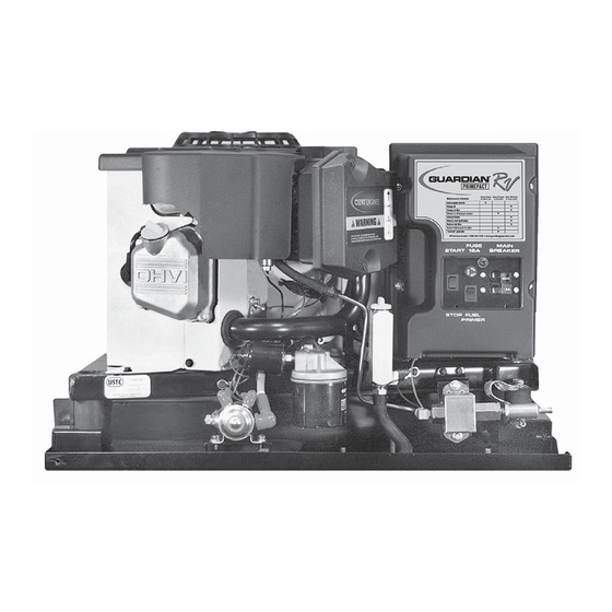
Section 1 – General Information Recreational Vehicle Generator PURPOSE AND SCOPE OF THE MANUAL These Installation Instructions have been prepared especially for the purpose of familiarizing installers and owners of the applicable equipment with the product's installation requirements. Give serious consideration to all information and instructions in the manual, both for safety and for continued reliable operation of the equipment. - Page 23 Section 1 – General Information Recreational Vehicle Generator Figure 1.2 – Major Features and Dimensions (Drawing 0F1127)
-
Page 24: Section 2 - Installation
Section 2 – Installation Recreational Vehicle Generator LOCATION AND SUPPORT 2.1.1 GENERATOR LOCATION The most desirable location for the generator set is between the vehicle's main frame members. However, this is seldom possible. Most units must be installed on the side of the vehicle and are difficult to rein- force. -
Page 25: Generator Restraint
2.1.4 GENERATOR RESTRAINT Use four 3/8"-16 hardened steel bolts (Grade 5) to fasten the generator to the supporting frame or the support tubing. These bolts must pass through (a) the generator mounting base, (b) the compartment floor (if a compartment is used) and (c) the supporting framework (Figure 2.3). -
Page 26: Sound Insulating Materials
Section 2 – Installation Recreational Vehicle Generator • If flexible metal conduit is used, it must be sealed internally at the end where it terminates inside the compartment’s electrical junction box. NOTE: Flexible metal conduit, due to its unique construc- tion, is NOT vapor tight along its entire length. -
Page 27: Compartment Floor Cutouts
Figure 2.7 – Typical Noise Abatement Figure 2.8 – Compartment Floor Cutout Section 2 – Installation Recreational Vehicle Generator 2.2.5 COMPARTMENT FLOOR CUTOUTS Provide openings in the generator compartment for the following items (Figure 2.8): • Engine exhaust and cooling air outlets •... -
Page 28: Cooling And Ventilating Air
Section 2 – Installation Recreational Vehicle Generator COOLING AND VENTILATING AIR It is absolutely essential that an adequate flow of air for cooling, ventilating and engine combustion be supplied to the generator set. Without sufficient airflow, the engine/generator quickly overheats. Such overheating can cause serious operating difficulties and also may cause fire and personal injury. -
Page 29: Compensating For Restrictions
Figure 2.12 – Air Inlet Using Ductwork Figure 2.13 – Air Inlet in Vehicle Skirt VEHICLE FLOOR MINIMUM CLEARANCE 1-1/2" 2.3.3 COMPENSATING FOR RESTRICTIONS Such materials as screening, louvers or expanded metal can restrict the free flow of air. Compensate for this restriction by making the actual air opening proportionately larger. -
Page 30: Generator Fuel Supply Line
Section 2 – Installation Recreational Vehicle Generator 2.4.1 FUEL TANK Either the generator must share the vehicle engine's fuel tank, or a separate fuel tank must be installed for the generator set. All fuel tanks installed on the vehicle must be constructed, installed and restrained so they comply with applicable codes, standards and regulations. -
Page 31: Some Important Considerations
Figure 2.15 – Typical Propane Gas Fuel System 2.5.2 SOME IMPORTANT CONSIDERATIONS When installing an LP gas system, consider seriously the following items: • All fittings, lines, hoses and clamps must be tight and free of leaks. Apply a pipe sealant to threads when assembling threaded connections. -
Page 32: Exhaust System
Section 2 – Installation Recreational Vehicle Generator The greater the airflow through the carburetor ven- turi, the lower the pressure at the venturi throat. The lower the pressure at the venturi throat, the greater the diaphragm movement, and the greater the move- ment of the regulator valve. -
Page 33: Electrical Connections
2.6.1 MUFFLERS AND SPARK ARRESTORS This muffler meets code and standard requirements of the U.S. Forest Service. Use only mufflers and parts approved by the manufacturer. Any person(s) installing an unapproved muffler, or an unapproved exhaust system part, or modifying an exhaust system in any way that might cause a hazard, is liable for any damage, injury or warranty expense that might be caused by such unapproved installation or modi-... -
Page 34: Generator Ac Connections
Section 2 – Installation Recreational Vehicle Generator 2.7.2 WIRING • Wiring should be of stranded copper to reduce the chance that vibration may cause breakage. • Wire gauge size should be large enough to handle at least 115 percent of the installed generator's rated maximum current. -
Page 35: Power Supply Cord
2.7.6 POWER SUPPLY CORD The power supply cord must comply with all appli- cable codes, standards and regulations. It must be large enough to handle the full amperage to which it will be subjected. Figure 2.19 – Installation With Isolation Receptacle The National Electrical Code (NFPA 70, 551-7) requires that ground fault circuit interrupters (GFCIs) on all external and some internal electrical recepta-... -
Page 36: Battery Installation
Section 2 – Installation Recreational Vehicle Generator BATTERY INSTALLATION 2.8.1 RECOMMENDED BATTERY Install a battery that meets the following require- ments: • The battery must be a 12-volt, automotive type storage battery. • For prevailing ambient temperatures above 32° F (0° C), use a battery rated 70 amp-hours and capable of delivering 400 cold-cranking amperes. -
Page 37: Remote Panel Models
2.9.1 REMOTE PANEL MODELS The remote panels mount a rocker type start/stop switch, a “Generator Run” advisory lamp and an hourmeter. The hourmeter should be used in con- junction with the maintenance operations found in Part I of this manual. •... -
Page 38: Installation Checklist
Section 3 – Post-installation Start-up Adjustments Recreational Vehicle Generator INSTALLATION CHECKLIST LOCATION AND SUPPORT ❑ Generator is properly located. ❑ Generator is properly supported. ❑ Generator is properly restrained. GENERATOR COMPARTMENT ❑ Compartment construction is proper. ❑ Holes/Openings are vapor-sealed. ❑... -
Page 39: Troubleshooting Guide
TROUBLESHOOTING GUIDE Problem The engine will not crank. The engine cranks but will not start. The engine starts hard and runs rough. The engine starts, but shuts down when the Start/Stop switch is released. The Start/Stop switch is set to Stop, but the engine continues to run. -
Page 40: Section 5 - Electrical Data Recreational Vehicle Generator Electrical Schematic And Wiring Diagram - Drawing No. 0D1754-A
Section 5 — Electrical Data Recreational Vehicle Generator Electrical Schematic and Wiring Diagram – Drawing No. 0D1754-A... - Page 41 Section 5 — Electrical Data Recreational Vehicle Generator Electrical Schematic and Wiring Diagram – Drawing No. 0D1754-A...
-
Page 42: Section 6 - Exploded Views And Parts Lists Recreational Vehicle Generator
Section 6 — Exploded Views and Parts Lists Recreational Vehicle Generator Regulator (Model 02010-2) – Drawing No. 0F1125-C... - Page 43 ITEM PART NO. 0D5694 0F4795 0F5022 0C6070 0C4680 0C4647 0C4643 0D3973 0E6183 072683A 0D3308 070728 0C5764A 0C4643A 0C6066 0C5968 0C5759 0C5761 0C6069 0C6731 0C6067 0C4706 0C6068 0C5762 045764 0C6606 0E4170 0C5760 Section 6 — Exploded Views and Parts Lists Recreational Vehicle Generator Regulator (Model 02010-2) –...
- Page 44 Section 6 — Exploded Views and Parts Lists Recreational Vehicle Generator Base and Pulleys (Model 04164-3) – Drawing No. 0F1124-C...
- Page 45 ITEM PART NO. QTY. DESCRIPTION ASSEMBLY REGULATOR (SEE E.V. 0F1125) 048031M #8 HOSE CLAMP 0F7065 16” HOSE, 1/2” I.D. PETROLEOM 022145 WASHER FLAT 5/16”- M8 022129 WASHER LOCK M8 - 5/16” 045771 NUT HEX M8-1.25 066849 SCREW, TAPTITE M5-0.8 X 16MM LONG 022473 WASHER FLAT 1/4”...
- Page 46 Section 6 — Exploded Views and Parts Lists Recreational Vehicle Generator Alternator and Panel (Model 04164-3) – Drawing No. 0D1776-F...
- Page 47 ITEM PART NO. QTY. DESCRIPTION 0C9675 LOWER BEARING CARRIER 0A5649H ROTOR ASSEM. 0A5646H STATOR ASSEM. 073159 BALL BEARING 031971 BALL BEARING 0C9674 UPPER BEARING CARRIER 0A6529 STUD-STATOR 052858 M8-1.25 FLANGE LOCK NUT 066386 BRUSH HOLDER 066849 M5-0.8 X 16 LG. TAPTITE 0A8475 SPECIAL LOCK WASHER, M5 0C3818...
- Page 48 Section 6 — Exploded Views and Parts Lists Recreational Vehicle Generator Engine Sheet Metal (Model 02010-2 and 04164-3) – Drawing No. 0D1760-H...
- Page 49 Engine Sheet Metal (Model 02010-2 and 04164-3) – Drawing No. 0D1760-H ITEM PART NO. 0A4323 045756 029289 SRV 091222D 067198N 067890 0A4456 056893 0A6358 091646 0G3279 0G3111 022717A 073132 061669 089685 022129 049813 057821 059637 0D9004A 059985 025034 0A8875 0A7299 0A9539 0A7838 038593...
- Page 50 Section 6 — Exploded Views and Parts Lists Recreational Vehicle Generator GN-410 Engine (Model 02010-2 and 04164-3) – Drawing No. 0E9615-A...
- Page 51 GN-410 Engine (Model 02010-2 and 04164-3) – Drawing No. 0E9615-A ITEM PART NO. QTY. DESCRIPTION 0G2565 RING SET, PISTON DIA 90 0E3221 CONNECTING ROD 0E1466 PISTON PIN 071983 PISTON PIN RETAINER 021713B CYLINDER HEAD GASKET 0A1442 FLANGED HEX HD. CAPSCREW M8-1.25 X 42 021742 M10 1.5 X 10⁵MM HHFL...
- Page 52 Section 6 — Exploded Views and Parts Lists Recreational Vehicle Generator Engine Accessories (Model 04164-3) – Drawing No. 0F1135...
- Page 53 ITEM PART NO. 0A6532 091039 051753 0E7585 089228 0A7336B 090970 0A6564 056893 0A6566 0A6780 096290 073111 081646 0A6563 0C3633 0A6581A 0C2332 092164 082025 0A7029 0A6913 091161 049813 092586 083512 0A6778 0A6785 0A6753 0A8222 086681 020753 022473 022097 0A6582 0A6503 0A6569 0A7660 0A6568 0A6567...
-
Page 54: Section 7 - Warranty Recreational Vehicle Generator
Section 7 – Warranty Recreational Vehicle Generator CALIFORNIA AND FEDERAL EMISSION CONTROL WARRANTY STATEMENT YOUR WARRANTY RIGHTS AND OBLIGATIONS The California Air Resources Board (CARB) and the United States Environmental Protection Agency (EPA), together with Generac Power Systems, Inc. (Generac), are pleased to explain the Emission Control System Warranty on your new engine.* New utility, and lawn and garden equipment engines must be designed, built and equipped to meet stringent anti-smog standards for the state of California and the federal government. -
Page 55: Emission Control System Warranty
Emission Control System Warranty (ECS Warranty) for 1997 and later model year engines: (a) Applicability: This warranty shall apply to 1997 and later model year engines. The ECS Warranty Period shall begin on the date the new engine or equipment is purchased by/delivered to its original, end-use purchaser/owner and shall continue for 24 consecutive months thereafter. - Page 56 Section 7 – Warranty Recreational Vehicle Generator GENERAC POWER SYSTEMS’ THREE-YEAR LIMITED WARRANTY FOR GUARDIAN RECREATIONAL VEHICLE GENERATORS NOTE: ALL UNITS MUST BE INSTALLED BY GENERAC POWER SYSTEMS AUTHORIZED SERVICE FACILITIES. For a period of 3 (three) years of operation from the date of original sale, Generac Power Systems, Inc. (Generac) will, at its option, repair or replace any part which, upon examination, inspection and testing by Generac or a Generac Authorized Warranty Service Facility, is found to be defective under normal use and service, in accordance with the warranty schedule set forth below.
Need help?
Do you have a question about the 02010-2, 04164-3 and is the answer not in the manual?
Questions and answers