Table of Contents
Advertisement
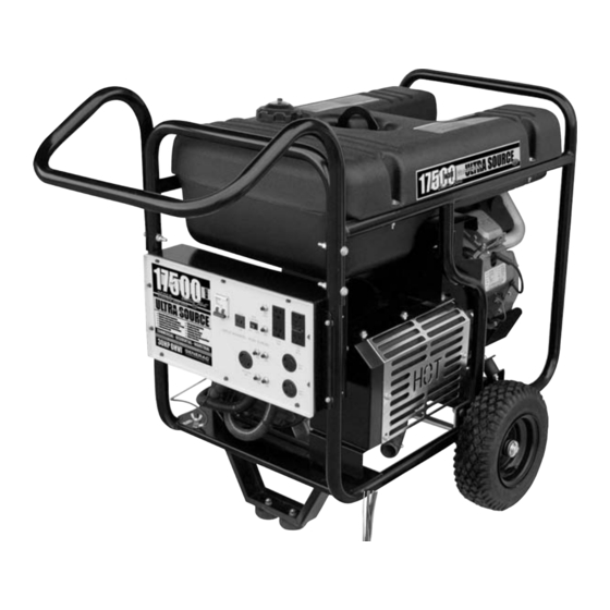
ULTRA SOURCE
Portable Generator
Owner's
Manual
• SAFETY
• ASSEMBLY
• OPERATION
• TROUBLESHOOTING
• ELECTRICAL DATA
• PARTS
• WARRANTY
COMMERCIAL • INDUSTRIAL • RESIDENTIAL
MODEL: 004583-0
17,500 Watt Portable Generator
and 60 amp manual transfer switch
AUTHORIZED DEALER SUPPORT:
with built-in load center
1-800-333-1322
Advertisement
Chapters
Table of Contents

Subscribe to Our Youtube Channel
Related Manuals for Generac Power Systems Guardian ULTRA SOURCE 004583-0


Summary of Contents for Generac Power Systems Guardian ULTRA SOURCE 004583-0
- Page 1 • SAFETY • ASSEMBLY • OPERATION • TROUBLESHOOTING • ELECTRICAL DATA • PARTS • WARRANTY COMMERCIAL • INDUSTRIAL • RESIDENTIAL MODEL: 004583-0 17,500 Watt Portable Generator and 60 amp manual transfer switch AUTHORIZED DEALER SUPPORT: with built-in load center 1-800-333-1322...
-
Page 2: Table Of Contents
Transfer Switch Installation ...19 Section 6 – Operation Of Generator With Manual Transfer Switch ...23 Using the Portable Generator and Transfer Switch ...23 Transfer to Generator Power Source when Utility Power Fails ...24 Transfer Back to Utility Power Source ...24 Section 7 –... -
Page 3: Introduction
INTRODUCTION Thank you for purchasing this model by Generac Power Systems, Inc. This model is a compact, high performance, air-cooled, engine driven generator designed to supply electrical power to operate electrical loads where no utility power is available or in place of utility due to a power outage. -
Page 4: Safety Rules
IMPORTANT SAFETY INSTRUCTIONS Portable Generator System SAVE THESE INSTRUCTIONS – The manufacturer suggests that these rules for safe operation be copied and posted near the unit's installation site. Safety should be stressed to all operators and potential operators of this equipment. -
Page 5: Electrical Hazards
If there are any questions pertaining to fire extinguishers, consult the local fire department. IMPORTANT SAFETY INSTRUCTIONS Portable Generator System • Do not smoke around the generator. Wipe up any fuel or oil spills immediately. -
Page 6: Section 1 - General Information
Section 1 – General Information Portable Generator System 1.1 UNPACKING • Set the palleted carton on a rigid flat surface. • Remove staples along bottom of carton that fasten carton to pallet. Open carton from top. • Remove all packaging material. -
Page 7: Battery Connection
(–). Make sure the connection is tight. • Double check all connections to ensure they are in the correct location and secure. See Figure 3. Section 1 - General Information Portable Generator System Figure 2 - Handle Assembly Figure 3 - Battery Connections Negative Cable... -
Page 8: Section 2 - Operation
Section 2 – Operation Portable Generator System 2.1 KNOW THE GENERATOR Read the Owner’s Manual and Safety Rules before operating this generator. Compare the generator to Figures 4 through 6 to become familiarized with the locations of various controls and adjustments. Save this manual for future reference. -
Page 9: Cord Sets And Connection Plugs
Section 2 – Operation Portable Generator System Figure 8 - 120 VAC, 20 Amp GFCI Receptacle Testing the GFCI: Test the GFCI outlet every month as follows: •... -
Page 10: 120/240 Vac, 30 Amp Receptacle
Section 2 – Operation Portable Generator System Use this receptacle to operate 120 Volt AC, 60 Hz, single phase loads requiring up to 3600 watts (3.6 kW) of power at 30 Amps. The outlet is protected by a 30 Amp push-to-reset circuit breaker. -
Page 11: Connecting Electrical Loads
Section 2 – Operation Portable Generator System 2.5 WATTAGE REFERENCE GUIDE Device........Running Watts *Air Conditioner (12,000 Btu) . -
Page 12: Before Starting The Generator
Section 2 – Operation Portable Generator System 2.6 BEFORE STARTING THE GENERATOR Prior to operating the generator, engine oil and gasoline will need to be added, as follows: 2.6.1 ADDING ENGINE OIL NOTE: When adding oil to the engine crankcase in the future, use only high quality detergent oil rated with API service classification SG, SH or SL SAE 30 weight. -
Page 13: To Start The Engine
Locate the Idle Control ON/OFF switch on the control panel and set it to the “OFF” position(Figure 16). Figure 16 - Idle Control Switch Section 2 – Operation Portable Generator System • Move engine CHOKE knob outward to “Full Choke” position (Figure 17). -
Page 14: Automatic Idle Control
Section 2 – Operation Portable Generator System 2.9 AUTOMATIC IDLE CONTROL This feature is designed to greatly improve fuel economy. When this switch is turned “On,” the engine will only run at its normal fast governed engine speed when electrical load is connected. When the load is removed, the engine will run at a reduced speed of 2100 RPM. -
Page 15: Section 3 - Maintenance
Gasoline Capacity Oil Type Oil Capacity Run Time/Fuel Consumption-1/2 Load Residential Portable Generator System Daily Every Season GPS 17,500 004583-0 17.5 kW 26.2 kW 120/240 72.9 Amps 145.8 Amps 60 Hz @ 3600 RPM Single Phase 12 Volts 10 Amperes... -
Page 16: General Recommendations
Section 3 — Maintenance Portable Generator System 3.3 GENERAL RECOMMENDATIONS The warranty of the generator does not cover items that have been subjected to operator abuse or negligence. To receive full value from the warranty, the operator must maintain the generator as instructed in this manual. -
Page 17: Replacing The Spark Plug
Figure 19 - Air Cleaner Pre-Cleaner Filter Section 3 — Maintenance Portable Generator System To clean or replace foam pre-cleaner: • Remove air cleaner cover, then foam pre-filter. • Wash pre-cleaner in soapy water. Squeeze pre-filter dry in clean cloth (DO NOT TWIST). -
Page 18: Adjusting Valve Clearance
Section 3 — Maintenance Portable Generator System 3.6 ADJUSTING VALVE CLEARANCE After the first 50 hours of operation, check the valve clearance in the engine and adjust if necessary. Important: If feeling uncomfortable about doing this procedure or the proper tools are not available, please take the generator to the nearest service center to have the valve clearance adjusted. -
Page 19: Long Term Storage
Clean the generator outer surfaces. Check that cooling air slots and openings on generator are open and unobstructed. • Store the unit in a clean, dry place. Section 3 — Maintenance Portable Generator System 3.9 OTHER STORAGE TIPS • Do not store gasoline from one season to another. •... -
Page 20: Section 4 - Troubleshooting
Section 4 — Troubleshooting Portable Generator System 4.1 TROUBLESHOOTING GUIDE PROBLEM CAUSE Engine is running, but no AC 1. Circuit breaker is open. output is available. 2. Poor connection or defective cord set. 3. Connected device is bad. 4. Fault in generator. -
Page 21: Section 5 - Installation For Manual Transfer Switch
70-NEC AND ANY LOCAL CODES THAT APPLY. Plan the location of the generator (must be on flat, level ground). Figure 24 shows the portable generator placed outside the home and connected to the weather protective external box. The ground rod and ground strap show a suggested location only. When fully installed the ground rod will not protrude above ground level. -
Page 22: Section 5 - Installation For Manual Transfer Switch Portable Generator System
Portable Generator System Select an area outside of your home about 10 feet away where you can easily transport the portable generator to and from. Keep in mind that the generator must have free air flow for proper operation and to ensure there is no possibility for exhaust gases to build up. - Page 23 The power inlet box must be locked to ensure safety and to discourage tampering. Section 5 — Installation for Manual Transfer Switch Portable Generator System Mount manual transfer switch with built-in emergency load center within one foot of main distribution panel (Figure 32). The manual transfer switch should be located to the right of the main distribution panel.
- Page 24 Connect the black and red wires to the 60 Amp double pole circuit breaker. Replace electrical distribution panel cover. Figure 34 - Connect Emergency Circuits Your Portable Generator Manual Transfer Switch is now installed. NOTE: If additional circuits are required to be protected. The manufacturer offers an additional 30A manual transfer switch and 30A Power Inlet Kit (Model 5341).
-
Page 25: Section 6 - Operation Of Generator With Manual Transfer Switch
50 Amp female receptacle which is inserted and twist-locked into the power inlet box. At the other end is the male connector (NEMA 14-50) which plugs into the portable generator’s control panel and is locked in place by the supplied spring retainer. NOTE: The power inlet box must be locked to ensure safety and to discourage tampering. -
Page 26: Transfer To Generator Power Source When Utility Power Fails
Section 6 — Operation of Generator with Manual Transfer Switch Portable Generator System 6.2 TRANSFER TO GENERATOR POWER SOURCE WHEN UTILITY POWER FAILS Move generator to within approximately 10 feet of the power inlet box. Connect ground strap to the generator’s grounding lug and to the grounding rod. -
Page 27: Section 7 - Notes
Section 7 — Notes Portable Generator System... - Page 28 Section 7 — Notes Portable Generator System...
-
Page 29: Section 8 - Electrical Data
Section 8 — Electrical Data Installation Diagram - Drawing No. 0G0907-B... - Page 30 Section 8 — Electrical Data Wiring Diagram, Portable Generator – Drawing No. 0G0731 120V/30A 120V/30A TWISTLOK TWISTLOK WHITE WHITE WHITE WHITE C.B. C.B. C.B. C.B. ENGINE WIRING ENGINE WIRING BLACK BLACK BATTERY BATTERY 120V/20A 120V/20A 120V/30A 120V/30A DUPLEX DUPLEX TWISTLOK...
- Page 31 SWITCH ELECTRONIC GOVERNOR / ELECTRONIC GOVERNOR / ENGINE SHUTDOWN P.C.B. ENGINE SHUTDOWN P.C.B. VOLTAGE VOLTAGE REGULATOR REGULATOR Wiring Diagram, Portable Generator – Drawing No. 0G0731 IDLE CONTROL IDLE CONTROL TRANSFORMERS TRANSFORMERS 10A AUTO 10A AUTO RESET BKR RESET BKR 12Vdc OUTLET 12Vdc OUTLET Section 8 —...
- Page 32 Section 8 — Electrical Data Electrical Schematic, Portable Generator – Drawing No. 0G0733 BATTERY CHARGE WINDING BATTERY CHARGE WINDING C1-5 C1-5 C1-4 C1-4 C1-3 C1-3 10A BATTERY CHARGE WINDING 10A BATTERY CHARGE WINDING C1-10 C1-10 C1-9 C1-9 C1-8 C1-8 ELECTRONIC...
- Page 33 GROUND GROUND (GRN) (GRN) NEUTRAL NEUTRAL (WHT) (WHT) NEUTRAL NEUTRAL (WHT) (WHT) CIRCUIT 9 CIRCUIT 9 NEUTRAL NEUTRAL (WHT) (WHT) CIRCUIT 11 CIRCUIT 11 NEUTRAL NEUTRAL (WHT) (WHT) CIRCUIT 13 CIRCUIT 13 NEUTRAL NEUTRAL (WHT) (WHT) CIRCUIT 15 CIRCUIT 15 CIRCUIT 1 CIRCUIT 1 (BRN)
-
Page 34: Section 9 - Exploded Views And Parts Lists
Section 9 — Exploded Views and Parts Lists Manual Transfer Switch with Load Center – Drawing No. 0G0939-B... - Page 35 ITEM PART NO. 0G0749 0G0748 0E7888 0E7888B 0E7888C 0E7888D 0E7888E 0E7888F 0G0863 0G0750 0G1494 Section 9 — Exploded Views and Parts Lists Manual Transfer Switch with Load Center – Drawing No. 0G0939-B QTY. DESCRIPTION BOX LOAD CENTER W/HARDWARE CIRCUIT BREAKER INTERLOCK CIRCUIT BREAKER 20A 2P CIRCUIT BREAKER 15A 1P CIRCUIT BREAKER 20A 1P...
- Page 36 Section 9 — Exploded Views and Parts Lists GT-990 & GT-760 Engine (Page 1) – Drawing No. 0E8589-Y...
- Page 37 ITEM PART NO. QTY. DESCRIPTION 0C5729 ASSEMBLY, CRANKCASE HOUSING WITH SLEEVE 0E9843 SEAL, 38 I.D. CRANKSHAFT 090388 SCREW, TAPTITE M6-1.0 X 12 BP 0C5372 ASSEMBLY, BREATHER 0C3005 GASKET, BREATHER COVER 0E3372B SEPARATOR, OIL BREATHER 0D8067A ASSEMBLY, HEAD #1 071983 RETAINER, PISTON PIN 20 0G0693 ASSY, ROCKER COVER W/BARB 043790...
- Page 38 Section 9 — Exploded Views and Parts Lists GT-990 & GT-760 Engine (Page 2) – Drawing No. 0E8589-Y...
- Page 39 ITEM PART NO. QTY. DESCRIPTION 0D6592 WINGNUT, AIRBOX 0D4511 PRECLEANER, AIR 0D9723 ELEMENT, AIR CLEANER 0E5302 STUD M6-1.0 X 73 0D4183 ADAPTOR, SPIT BACK 0D6327 GASKET, SPITBACK 0D2774B BASE, AIRBOX 0D5125 SPRING, WINTER/SUMMER VALVE 0D2930 VALVE, SUMMER / WINTER 0D4612A SNORKEL, AIR INTAKE 0D6143 TUBE, HEAT RISER 50.8 I.D.
- Page 40 Section 9 — Exploded Views and Parts Lists Generator – Drawing No. 0G0742-A...
- Page 41 ITEM PART NO. 0C6934 0G1177 0D2136 0G11760SRV 0D21350SRV 0C6043B 0D2492 0D2726 0C4138 0D3547 031971 0C3168 0D1838 0D3549 0C7038E 032712 0D4662 0C7038D 0C7758 0388050AF0 0C2417A 082121C 066386 0C2824 0A2038 022237 022511 022131 051731 022145 049820 043116 022129 022259 059637 0D5100 0D5823 0C8565 0D5833 0D5834...
- Page 42 Section 9 — Exploded Views and Parts Lists Control Panel – Drawing No. 0G0727-B...
- Page 43 ITEM PART NO. QTY. DESCRIPTION 087968 SWITCH, ROCKER -/0 090418 OUTLET, 12VDC SNAP 0D6640 COVER, GOVERNOR CONTROL 090987 SCREW PPHM M3-0.5 X 12 0D8740 PANEL, SHEET METAL (15 KW) 0G0309 PANEL, SHEET METAL (17.5 KW) 068868 OUTLET 30A 120V RECEPT 0G1093 SCREW SFILHM #8-32 X 5/8 LG (17.5 KW ONLY)
- Page 44 Section 9 — Exploded Views and Parts Lists Frame, Handle & Wheel Kit – Drawing No. 0E0695-B 12 13 POWER WIRE TO ENGINE Detail of Battery Tray 40 26 29/51...
- Page 45 ITEM PART NO. QTY. DESCRIPTION 057058 SCREW HHC M6-1.0 X 55 0D5315 RUBBER TANK MOUNT 0D4570 CAP, FUEL WITH GAUGE & VENT 0D22850SRV KIT, FUEL TANK 045771 NUT HEX M8-1.25 022129 WASHER LOCK M8-5/16 022145 WASHER FLAT 5/16 0D4565 BRACKET BATTERY 0D3545 BOLT,BATTERY J-BOLT 022287...
-
Page 46: Section 10 - Warranty
Section 10 – Warranty Portable Generator System CALIFORNIA EMISSION CONTROL WARRANTY STATEMENT YOUR WARRANTY RIGHTS AND OBLIGATIONS The California Air Resources Board (CARB) and Generac Power Systems, Inc. (Generac) are pleased to explain the Emission Control System warranty on your new engine. In California, new off-road Large Spark-Ignition (LSI) engines must be designed, built and equipped to meet the state's stringent anti-smog standards. -
Page 47: Emission Control System Warranty
Air cleaner * Generac engine types covered by this warranty statement include the following: 1) Prepackaged Standby Generator 2) Auxiliary Power Unit (APU) Generator 3) Portable Generator 4) Standby Generator EMISSION CONTROL SYSTEM WARRANTY EMISSION RELATED PARTS INCLUDE THE FOLLOWING:... -
Page 48: Consumer Application
ULTRA SOURCE 17,500 WATT GENERATOR WITH MANUAL TRANSFER SWITCH For a period of two years from the date of original sale, Generac Power Systems, Inc. (Generac) warrants its portable generator and accompanying transfer switch will be free from defects in materials and workmanship for the items and period set forth below. Generac will, at its option, repair or replace any part which, upon examination, inspection and testing by Generac or a Generac Authorized Warranty Service Dealer, is found to be defective. -
Page 49: Manual Del Propietario
• DATOS ELÉCTRICOS • PIEZAS • GARANTÍA ASISTENCIA DE CONCESIONARIOS AUTORIZADOS: 1-800-333-1322 ULTRA SOURCE Generador Portátil COMERCIAL • INDUSTRIAL • RESIDENCIAL MODELO: 004583-0 Generador portátil de 17,500 vatios y conmutador de transferencia manual de 60 con centro de carga integrado amperios... - Page 50 Contenido Sistema de generador portátil residencial Introducción ...1 Lea detenidamente este manual ...1 Reglas de seguridad ...2 Índice de normas ...3 Sección 1 – Información general ...4 Desempaque ...4 1.1.1 Caja de accesorios ...4 Montaje 4 1.2.1 Montaje del juego de la rueda ...4 1.2.2 Montaje de la manija ...4 1.2.3...
-
Page 51: Introducción
INTRODUCCIÓN Agradecemos que haya comprado este modelo de Generac Power Systems, Inc. Este modelo es un generador accionado por motor que es compacto, de alto rendimiento, enfriado por aire, y que está diseñado para suministrar potencia eléctrica para operar cargas eléctricas en áreas que carecen de electricidad o en lugar del suministro eléctrico cuando hay apagones. -
Page 52: Instrucciones Importantes De Seguridad
INSTRUCCIONES IMPORTANTES DE SEGURIDAD Sistema de generador portátil GUARDE ESTAS INSTRUCCIONES – El fabricante sugiere que estas reglas de operación segura se copien y se coloquen cerca del sitio de instalación de la unidad. Se debe enfatizar la seguridad a todos los operadores y operadores potenciales de este equipo. •... -
Page 53: Índice De Normas
• Mantenga las manos, pies, ropa, etc. lejos de las correas de transmisión, ventiladores y otras partes en movimiento o calientes. Nunca quite ningún protector de las correas de transmisión o de los ventiladores mientras la unidad está funcionando. • El flujo libre y adecuado del aire de ventilación y del aire de enfriamiento es crítico para la operación correcta del generador. -
Page 54: Sección 1 - Información General
Sección 1 – Información general INFORMACIÓN Sistema de generador portátil GENERAL 1.1 DESEMPAQUE • Coloque la caja con la paleta sobre una superficie plana y rígida. • Quite las grapas que se encuentran a lo largo de la parte inferior de la caja que fijan la caja con la paleta. -
Page 55: Conexión De La Batería
PAC DE 5/16 X 2-1/2 ARANDELA PLANA ARANDELA PLANA ARANDELA DE PRESIÓN TUERCA PRESIÓN 1.2.3 CONEXIÓN DE LA BATERÍA • La batería que se envía con el generador va completamente cargada. Se debe tener cuidado al conectar la batería. NOTA: Una batería puede perder su carga cuando no se usa por periodos de tiempo prolongados. -
Page 56: Sección 2 - Operación
Sección 2 – Operación Sistema de generador portátil 2.1 FAMILIARÍCESE CON SU GENERADOR Lea el Manual del Propietario y las Reglas de Seguridad antes de operar este generador. Compare el generador con las Figuras 4 a 6 para familiarizarse con la ubicación de los varios controles y ajustes. -
Page 57: Juegos De Cordones Eléctricosy Enchufes De Conexión
Figura 6 - Panel de control del motor 2.2 JUEGOS DE CORDONES ELÉCTRICOS Y ENCHUFES DE CONEXIÓN 2.2.1 RECEPTÁCULO DÚPLEX DE 120 VCA, 20 AMPERIOS Este receptáculo es un tomacorriente de 120 voltios protegida contra sobrecargas por un disyuntor de restablecimiento por presión de 20 amperios (Figura 7). - Page 58 Sección 2 – Operación Sistema de generador portátil • Este tomacorriente está protegido contra sobrecargas con un disyuntor de restablecimiento por presión de 20 amperios. Use cada tomacorriente para alimentar cargas eléctricas de 120 voltios de CA, monofásicas de 60 Hz que requieran hasta una corriente combinada de 2400 vatios (2.4 kW) o 20 amperios.
-
Page 59: Cómo Usar El Generador
2.3 CÓMO USAR EL GENERADOR Si hay algún problema en la operación del generador, por favor llame a la línea telefónica de ayuda sobre generadores, 1-800-333-1322. 2.3.1 CONEXIÓN A TIERRA DEL GENERADOR El Código Eléctrico Nacional requiere que el bastidor y las piezas eléctricamente conductivas externas de este generador se conecten a una conexión a tierra aprobada (Figura 13). -
Page 60: Guía De Referencia Del Vataje
Sección 2 – Operación Sistema de generador portátil 2.5 GUÍA DE REFERENCIA DEL VATAJE Dispositivo....... Vataje de operación *Unidad de acondicionamiento de aire (12,000 Btu) . -
Page 61: Adición De Gasolina
2.6.2 ADICIÓN DE GASOLINA Nunca llene el tanque de combustible en interiores. Nunca llene el tanque de combustible cuando el motor esté funcionando o cuando esté caliente. NO encienda un cigarrillo ni fume al llenar el tanque de combustible. ... -
Page 62: Detención Del Motor
Sección 2 – Operación Sistema de generador portátil • Mueva la perilla CHOKE (ESTRANGULACIÓN) a la posición “Full Choke” (Estrangulación completa) (Figura 17). Figura 17 - Posición de Estrangulación Completa. • Para arrancar el motor, presione y mantenga presionado el conmutador Arranque/Funcionamiento/Parada en la posición "Start"... -
Page 63: Detección De Baja Presión De Aceite
2.11.2 DETECCIÓN DE BAJA PRESIÓN DE ACEITE Si el sistema detecta una presión de aceite baja durante la operación, el motor se apaga. 2.11.3 REARRANQUE Es posible que el motor NO arranque si trata de rearrancarlo en un lapso de 10 segundos después de que se apague. El sistema requiere de 5 a 10 segundos para restablecerse. -
Page 64: Sección 3 - Mantenimiento
Verano – SAE 30 o 10W-30 Invierno – Sintético 5W-20 o 5W-30 con cambio de filtro = 1.7 cuartos sin cambio de filtro = 1.4 cuartos 10 horas / 1.6 galones por hora Cada temporada Cada temporada 004583-0 17.5 kW 26.2 kW 120/240 12 voltios... -
Page 65: Recomendaciones Generales
3.3 RECOMENDACIONES GENERALES La garantía del generador no cubre artículos que han sido sometidos a abuso o negligencia por parte del operador. Para aprovechar el valor total de la garantía, el operador debe mantener el generador de acuerdo con las instrucciones de este manual. Será... -
Page 66: Reemplazo De Las Bujías
Sección 3 — Mantenimiento MANTENIMIENTO Sistema de generador portátil 3.3.6 REEMPLAZO DE LA BUJÍA Use una bujía Champion RC14YC o una equivalente. El espacio de aire correcto es de 1.01 mm (0.040 pulg.) (Figura 18). Reemplace la bujía cada año. Esto ayudará a que el motor arranque más fácilmente y funcione mejor. -
Page 67: Ajuste De La Holgura De La Válvula
Limpie e inspeccione la malla amortiguadora de chispas de la siguiente manera: • Quite la abrazadera que fija la malla quitándole el tornillo. • Deslice la malla amortiguadora de chispas del tubo de cola. • Inspeccione la malla y reemplácela si está desgastada, perforada o si tiene cualquier otro daño. -
Page 68: Almacenamiento A Largo Plazo
Sección 3 — Mantenimiento MANTENIMIENTO Sistema de generador portátil 3.8 ALMACENAMIENTO A LARGO PLAZO IMPORTANTE: Es importante evitar la formación de depósitos de goma en las piezas del sistema de combustible, como en el carburador, la manguera de combustible o el tanque durante el almacenamiento. -
Page 69: Sección 4 - Localización Y Resolución De Problemas
4.1 GUÍA DE LOCALIZACIÓN Y RESOLUCIÓN DE PROBLEMAS PROBLEMA CAUSA El motor está funcionando, 1. El disyuntor está abierto. pero no hay disponible una 2. Hay una mala conexión o el juego de cordones salida de CA. 3. El dispositivo conectado está descompuesto. 4. - Page 70 Sección 4 — Localización y resolución de problemas Sistema de generador portátil PROBLEMA CAUSA El motor no tiene potencia. 1. La carga es demasiado alta. 2. El filtro de aire está sucio. 3. El motor necesita servicio. El motor vacila. 1.
-
Page 71: Sección 5 - Instalación Del Conmutador
5.1 CONTENIDO DEL JUEGO Caja de entrada de potencia (Figura 22) Esta caja está precableada con el receptáculo macho de 50 amperios y se ubica fuera de la casa, en donde se operará el generador. Figura 22 - Caja de entrada de potencia Conmutador de transferencia manual precableado y centro de carga de emergencia con 16 circuitos (Figura 23) Instalado a una distancia de un pie del panel de distribución... - Page 72 INSTALACIÓN Sección 5 – Instalación del conmutador de transferencia manual Sistema de generador portátil Figura 24 - Ubicación del generador El generador se debe colocar tan lejos de la casa como el cordón eléctrico lo permita. Se entiende que el cordón eléctrico no debe quedar tirante y que quedará...
-
Page 73: Transferencia Manual
7a. Levante la cubierta de la caja de entrada de potencia y quite los tornillos de la placa de la cubierta interna y la placa de la cubierta interna. Quite el agujero ciego de la parte central inferior de la caja. - Page 74 Sección 5 – Instalación del conmutador de transferencia manual INSTALACIÓN Sistema de generador portátil Aunque puede optar por realizar usted mismo las conexiones eléctricas, el fabricante recomienda que un electricista licenciado o una persona con conocimiento completo de la electricidad realice los procedimientos que se describen en las secciones 10a y 10b.
-
Page 75: Uso Del Generador Portátil Y Del Conmutador De Transferencia
Sección 6 — Operación del generador con conmutador de transferencia manual 11. Instale el disyuntor bipolar de 60 amperios que compró en el panel de distribución eléctrica principal (Figura 34). Este disyuntor debe ser compatible con su panel de distribución eléctrica principal. - Page 76 Sección 6 — Operación del generador con conmutador de transferencia manual Sistema de generador portátil Receptáculo NEMA 14-50, de 50 amperios 17.500 vatios Ultra Fuente generador portátil Panel de control del generador Receptáculo CC de 12 Voltios POWERFUL: SAFE POWER: Superior motor-starting Electronic governor, automatic capabilities starts a 5-ton air conditioner...
-
Page 77: Transferencia A La Fuente De Potencia Del Generador Cuando Falla El Suministro Eléctrico
Sección 6 — Operación del generador con conmutador de transferencia manual 6.2 TRANSFERENCIA A LA FUENTE DE POTENCIA DEL GENERADOR CUANDO FALLA EL SUMINISTRO ELÉCTRICO Mueva el generador a una distancia aproximada de 10 pies de la caja de entrada de potencia. Conecte la correa de conexión a tierra a la orejeta de conexión a tierra del generador y a la barra de conexión a tierra. -
Page 78: Sección 7 - Garantía
Sección 7 – Garantía Sistema de generador portátil DECLARACIÓN DE LA GARANTÍA DE LOS SISTEMAS DE CONTROL DE EMISIONES DE CALIFORNIA La Junta de Recursos de Aire de California (California Air Resources Board, CARB) y Generac Power Systems, Inc. (Generac) se complacen en explicarle la garantía del sistema de control de emisiones de su nuevo motor. -
Page 79: Garantía Del Sistema De Control De Emisiones
Garantía del sistema de control de emisiones (Emission Control System, ECS) para motores LSI de 2001 y modelos posteriores: (a) Aplicabilidad: Esta garantía aplicará a los motores de 2001 y de años posteriores. El periodo de la garantía ECS comenzará en la fecha de la compra del nuevo motor o equipo o de su entrega a su propietario/comprador y usuario final original, y terminará... - Page 80 Sección 7 – Garantía Sistema de generador portátil GARANTÍA LIMITADA POR DOS AÑOS DE GENERAC POWER SYSTEMS DEL GENERADOR GUARDIAN ® ULTRA SOURCE DE 17,500 VATIOS CON CONMUTADOR DE TRANSFERENCIA MANUAL Durante un periodo de dos años, a partir de la fecha original de la compra, Generac Power Systems, Inc. (Generac) garantiza que su generador portátil y el conmutador de transferencia que lo acompaña estarán libres de defectos en los materiales y en la mano de obra en los artículos y durante el periodo que se establece a continuación.
Need help?
Do you have a question about the Guardian ULTRA SOURCE 004583-0 and is the answer not in the manual?
Questions and answers