
Related Manuals for Agilent Technologies U8030A Series


Summary of Contents for Agilent Technologies U8030A Series
- Page 1 Agilent U8030A Series Triple Output DC Power Supply User’s Guide Agilent Technologies...
-
Page 2: Safety Notices
U8031-90004 ity and fitness for a particular purpose. age to the product or loss of impor- Agilent shall not be liable for errors or for Edition tant data. Do not proceed beyond a incidental or consequential damages in... -
Page 3: Safety Symbols
DC (Direct current or voltage) be operated with one terminal at earth potential. AC (Alternating current or voltage) Positive binding post Protective conductor terminal Negative binding post Out position of a bi-stable push control U8030A Series User’s Guide... -
Page 4: Safety Considerations
Agilent Technologies assumes no liability for the customer’s failure to comply with these requirements. • Use the device with the cables provided with the shipment. -
Page 5: Environmental Conditions
Up to 2000 meters Installation category Installation Category II Pollution degree Pollution Degree 2 The U8030A Series Triple Output DC Power Supply complies with the following N O T E safety and EMC requirements: • IEC61326-1:2005 / EN61326-1:2006 • CISPR 11:2003/ EN55011:2007 •... - Page 6 The CSA mark is a registered substance elements are expected to trademark of the Canadian Standards leak or deteriorate during normal use. Association. Forty years is the expected useful life of the product. U8030A Series User’s Guide...
- Page 7 “Monitoring and Control Instrument” product. The affixed product label is as shown below. Do not dispose in domestic household waste. To return this unwanted instrument, contact your nearest Agilent Service Center, or visit www.agilent.com/environment/product for more information.
- Page 8 Declaration of Conformity (DoC) The Declaration of Conformity (DoC) for this instrument is available on the Agilent website. You can search the DoC by its product model or description at the web address below. http://regulations.corporate.agilent.com/DoC/search.htm If you are unable to search for the respective DoC, please contact your N O T E local Agilent representative.
-
Page 9: Table Of Contents
Overview Display screen Output connections Operating Your Power Supply Cooling Bench operation Cleaning List of Error Codes System errors Power channel errors Operation and Features Constant Voltage Operation Constant Current Operation 5 V Operation Overload condition U8030A Series User’s Guide... - Page 10 Set the OCP trip level and enable the OCP Disable the OCP Clear the overcurrent condition Keylock Operation System-Related Operations Reset to the factory defaults Power-on self-test Display the firmware and board versions Extending the Voltage and Current Range Series connection Parallel connection U8030A Series User’s Guide...
- Page 11 Characteristics and Specifications Electrical Specifications Physical Characteristics Supplemental Characteristics Protection Features AC Power Input Specifications Environmental Specifications Connection Specifications U8030A Series User’s Guide...
- Page 12 U8030A Series User’s Guide...
- Page 13 List of Figures Figure 1-1 Rack-mount adapter kit Figure 1-2 U8030A Series rack-mount dimensions Figure 1-3 U8030A Series dimensions Figure 1-4 The front panel at a glance Figure 1-5 The rear panel at a glance Figure 1-6 The LCD display at a glance...
- Page 14 U8030A Series User’s Guide...
-
Page 15: List Of Tables
List of power channel error codes Table 3-1 Electrical specifications Table 3-2 Physical characteristics Table 3-3 Supplemental characteristics Table 3-4 Protection features Table 3-5 AC power input specifications Table 3-6 Environmental specifications Table 3-7 Connection specifications U8030A Series User’s Guide... - Page 16 U8030A Series User’s Guide...
- Page 17 U8030A Series Triple Output DC Power Supply User’s Guide Introduction About This Manual Documentation map Safety notes Preparing Your Power Supply Checking the shipment Connecting power to the instrument Checking the instrument output Rack-mounting the instrument Enabling or disabling the backlight...
-
Page 18: Introduction
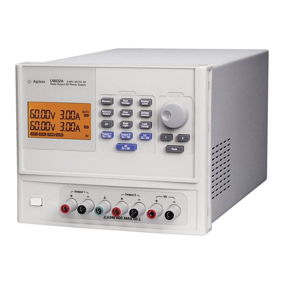
About This Manual About This Manual The descriptions and instructions in this manual apply to the Agilent U8031A and U8032A triple output DC power supplies (hereafter referred to as the power supply). The model U8032A appears in all illustrations. Documentation map The following manuals are available for your power supply. -
Page 19: Preparing Your Power Supply
CD- ROM Keep the original packaging in case the power supply has to be returned to Agilent in the future. If you return the power supply for service, attach a tag identifying the owner and model number. Also, include a brief description of the problem. -
Page 20: Connecting Power To The Instrument
If the instrument does not turn on Use the following steps to help solve problems you might encounter when turning on the instrument. If you need more help, refer to the U8030A Series Service Guide for instructions on returning the instrument to Agilent Technologies for service. -
Page 21: Checking The Instrument Output
The following procedures check to ensure that the power supply develops its rated outputs and properly responds to operation from the front panel. For complete performance and verification tests, refer to the U8030A Series Service Guide. From the front- panel VFD (vacuum- fluorescent display), you... - Page 22 2 Connect a short across the (+) and (–) output terminals of Output 1 with an insulated test lead. Use a wire size sufficient to handle the maximum current (refer to the American Wire Gauge standard). U8030A Series User’s Guide...
- Page 23 7 switch between Output 1 and Output 2 (the OUT1 and OUT2 annunciators will turn on and off respectively). 9 Disable the outputs, turn off the power supply, and remove the short from the output terminals. U8030A Series User’s Guide...
-
Page 24: Rack-Mounting The Instrument
Instructions and mounting hardware are included with the rack- mounting kit. To rack- mount a single instrument, order adapter kit 5063- 9245. Figure 1-1 Rack-mount adapter kit 24.4 mm 12.7 mm 338.2 mm 191 mm Figure 1-2 U8030A Series rack-mount dimensions U8030A Series User’s Guide... -
Page 25: Enabling Or Disabling The Backlight
Press the [Back Light] button to disable the LCD backlight. If viewing the display becomes difficult in low- light conditions, press the [Back Light] button again to enable the LCD backlight. The LCD backlight is enabled by default upon power-on. N O T E U8030A Series User’s Guide... -
Page 26: Your Power Supply In Brief
Introduction Your Power Supply in Brief Your Power Supply in Brief Dimensions 179.0 mm 379.0 mm 212.3 mm Figure 1-3 U8030A Series dimensions U8030A Series User’s Guide... -
Page 27: Overview
Table 1-2 Front panel legends and descriptions Legend Description LCD display Displays the instrument settings and readings. Stores the current operating state or recalls a [Memory] previously stored operating state from the available memory locations (M1, M2, or M3). U8030A Series User’s Guide... - Page 28 LCD display Selects the knob control function for Output 1 adjustment. Selects the knob control function for Output 2 adjustment. Sets the voltage and current settings of Output 1 [Track] or Output 2 to follow each other. U8030A Series User’s Guide...
-
Page 29: Figure 1-5 The Rear Panel At A Glance
Positive and negative binding posts for 5 V output 5 V binding posts wire connections. Rear panel The rear panel parts of your power supply are described in this section. Figure 1-5 The rear panel at a glance U8030A Series User’s Guide... -
Page 30: Display Screen
Ventilation fan to exhaust heat and air from the Ventilation fan instrument. Physical lock Enables the physical lock mechanism. mechanism Display screen The display annunciators of your power supply are described in this section. Figure 1-6 The LCD display at a glance U8030A Series User’s Guide... -
Page 31: Table 1-4 Lcd Display Legends And Descriptions
When the OCP1 annunciator is steady, the overcurrent protection function for Output 1 is enabled. OCP1 When the OCP1 annunciator is blinking, an overcurrent condition has occurred. The power supply output is disabled until the trip is cleared. U8030A Series User’s Guide... - Page 32 Output 1 binding posts. OUT2 Output 2 is selected. The power supply is supplying constant voltage from the Output 2 binding posts. The power supply is supplying constant current from the Output 2 binding posts. U8030A Series User’s Guide...
-
Page 33: Output Connections
The voltage drops across the load wires should be limited to less than 2 V. Refer to the American Wire Gauge (AWG) standard to calculate the voltage drop for some commonly used AWG wire copper. U8030A Series User’s Guide... -
Page 34: Operating Your Power Supply
40 °C to 55 °C. A fan cools the power supply by drawing air through the sides and exhausting it out the back. Using an Agilent rack- mount will not impede the flow of air. Bench operation... -
Page 35: List Of Error Codes
Analog board firmware update error Analog board firmware checksum error EEPROM read error Failed to calibrate voltage DAC Failed to calibrate voltage ADC Failed to calibrate OVP Failed to calibrate current DAC Failed to calibrate current ADC U8030A Series User’s Guide... - Page 36 Analog board unknown error Over temperature Failed EEPROM test Failed voltage +15 V Failed voltage +5 V Failed voltage +2.5 V Failed voltage +1 V Failed ADC test Failed DAC test Failed communication with analog board Unsupported analog board U8030A Series User’s Guide...
- Page 37 U8030A Series Triple Output DC Power Supply User’s Guide Operation and Features Constant Voltage Operation Constant Current Operation 5 V Operation Track Mode Operation Output On/Off Operation Memory Operations Memory Output Operations Programming the Overvoltage Protection Programming the Overcurrent Protection...
-
Page 38: Operation And Features
When you press the [Display Limit] button, the voltage and current limit N O T E values will be shown on the display for about five seconds. If there is no activity detected, the display will return to the meter mode. U8030A Series User’s Guide... - Page 39 Verify that the power supply is in the constant voltage mode. Ensure that N O T E the constant voltage (CV) annunciator is on. If the constant current (CC) annunciator is on instead, choose a higher current limit. U8030A Series User’s Guide...
-
Page 40: Constant Current Operation
• Press the [Display Limit] button to set the display to the limit mode. The LIMIT annunciator turns on. • The display will show the voltage and current limit values for the selected output. • The display for the non- selected output remains unchanged. U8030A Series User’s Guide... - Page 41 Verify that the power supply is in the constant current mode. Ensure that N O T E the constant current (CC) annunciator is on. If the constant voltage (CV) annunciator is on instead, choose a higher voltage limit. U8030A Series User’s Guide...
-
Page 42: 5 V Operation
• The 5 V annunciator turns off. • The 5VOL annunciator turns on. • To clear the overload condition and enable the 5V output in a single step, press the [5 V On/Off] button. U8030A Series User’s Guide... -
Page 43: Circuit Fault Condition
• The 5 V annunciator blinks. • The circuit fault condition might be cleared by cycling the unit power. • If the fault condition persists, stop using the unit and send it to an authorized service center for repair. U8030A Series User’s Guide... -
Page 44: Track Mode Operation
• The voltage setting of the non- selected output is set to the same voltage setting of the selected output. 4 Disable the track mode. • Press the [Track] button again. The TRACK annunciator turns off. • The track mode is disabled. U8030A Series User’s Guide... -
Page 45: Output On/Off Operation
• If any of the outputs are enabled, pressing the [All On/Off] button will disable all the outputs. If all the outputs are disabled, pressing the [All On/Off] button will enable N O T E all the outputs. U8030A Series User’s Guide... -
Page 46: Turn On Or Off Individual Outputs
• The display Output 1 and Output 2 on line 1 and 2 remains unchanged. • Press the [5 V On/Off] button again to disable the 5 V output. The OFF annunciator turns on only when all the three outputs are disabled. N O T E U8030A Series User’s Guide... -
Page 47: Memory Operations
• The display will show dOnE. • The M1, M2, and M3 annunciators turn off. To cancel this operation, allow the unit to idle for five seconds. N O T E U8030A Series User’s Guide... -
Page 48: Recalling An Operating State
• The display will show dOnE. • The M1, M2, and M3 annunciators turn off. To cancel this operation, allow the unit to idle for five seconds. N O T E U8030A Series User’s Guide... -
Page 49: Memory Output Operations
• After waiting for Δt , the operating state from M3 memory location is recalled. • The M3 annunciator blinks for two seconds. The M1 and M2 annunciators are steadily on. • The memory output operation is completed. U8030A Series User’s Guide... -
Page 50: Enable The Memory Output Loop Operation
2 Cancel the memory output loop operation. • Pressing the [Memory Output] button during the memory output loop operation will terminate the operation immediately. • All outputs will be disabled. • The OFF annunciator turns on. U8030A Series User’s Guide... -
Page 51: Program The Memory Output Time Interval
• You can set the time interval within the range of 0 s to 9999.99 s. • Press and hold the [Δt] button to save the setting. • The display shows dOnE. To cancel this operation, allow the unit to idle for five seconds. N O T E U8030A Series User’s Guide... -
Page 52: Programming The Overvoltage Protection
• The display will show the OVP value for the selected output. • The V annunciator will blink continuously. 3 Turn the knob to adjust the OVP value. • While the V annunciator is blinking, turn the knob and adjust to the desired OVP value. U8030A Series User’s Guide... -
Page 53: Disable The Ovp
The OVP trip can only occur if the corresponding output is enabled. When the OVP trip occurs, the corresponding output is disabled automatically. • If the OVP trip occurs on Output 1, the display shows triP on line 1 and the OVP1 annunciator blinks. U8030A Series User’s Guide... - Page 54 • The corresponding annunciator (OUT1 or OUT2) turns 2 Clear the OVP trip. • Press the [Over Voltage] button again to clear the OVP trip. If the OVP trip persists, decrease the voltage limit settings to clear the N O T E tripping. U8030A Series User’s Guide...
-
Page 55: Programming The Overcurrent Protection
• The display will show the OCP value for the selected output. • The A annunciator will blink continuously. 3 Turn the knob to adjust the OCP value. • While the A annunciator is blinking, turn the knob and adjust to the desired OCP value. U8030A Series User’s Guide... -
Page 56: Disable The Ocp
The OCP trip can only occur if the corresponding output is enabled. When the OCP trip occurs, the corresponding output is disabled automatically. • If the OCP trip occurs on Output 1, the display shows triP on line 1 and the OCP1 annunciator blinks. U8030A Series User’s Guide... - Page 57 • The corresponding annunciator (OUT1 or OUT2) turns 2 Clear the OCP trip. • Press the [Over Current] button again to clear the OCP trip. If the OCP trip persists, decrease the current limit settings to clear the N O T E tripping. U8030A Series User’s Guide...
-
Page 58: Keylock Operation
• Press and hold the [Lock/Unlock] button for more than one second. • While the [Lock/Unlock] button is being held down, the display will show HOLd until the keylock is disabled. • After the keylock is disabled, the LOCK annunciator turns off. U8030A Series User’s Guide... -
Page 59: System-Related Operations
If the test fails, the display will show Err along with the error code. For N O T E more information, refer to the “List of Error Codes” on page 35. U8030A Series User’s Guide... -
Page 60: Display The Firmware And Board Versions
• After that, the display shows: • the firmware and board versions of analog board 1 on line 1, and • the firmware and board versions of analog board 2 on line 2 for one second. U8030A Series User’s Guide... -
Page 61: Extending The Voltage And Current Range
When serial connection is used, the output voltage is the sum of output voltage across all power supplies, while the output current is the output current from an individual power supply. Each power supply must be adjusted to obtain the total output voltage. U8030A Series User’s Guide... -
Page 62: Parallel Connection
This will happen until the output voltage equals the output of the other supply, and the other supply will remain in constant voltage operation; only delivering that fraction of rated output current that is necessary to fulfill the total load demand. U8030A Series User’s Guide... -
Page 63: Figure 2-2 Connecting Units In Parallel
Operation and Features Extending the Voltage and Current Range Figure 2-2 Connecting units in parallel U8030A Series User’s Guide... - Page 64 Operation and Features Extending the Voltage and Current Range THIS PAGE HAS BEEN INTENTIONALLY LEFT BLANK. U8030A Series User’s Guide...
- Page 65 U8030A Series Triple Output DC Power Supply User’s Guide Characteristics and Specifications Electrical Specifications Physical Characteristics Supplemental Characteristics Protection Features AC Power Input Specifications Environmental Specifications Connection Specifications This chapter lists the characteristics and specifications of the U8031A and U8032A triple output DC power supplies.
-
Page 66: Characteristics And Specifications
Based on calculation at temperature of 18 °C to 28 °C and bandwidth at 20 Hz to 20 MHz. Load transient response time <50 μs Within 15 mV from full load to half load and from half load to full load. U8030A Series User’s Guide... -
Page 67: Physical Characteristics
±240 V Physical Characteristics Table 3-2 Physical characteristics Parameter U8031A/U8032A Display LCD with amber backlight Rotary knob for reading adjustment Size 4U, half rack 179.0 mm × 212.3 mm × 379.0 mm Dimensions Weight 8.2 kg U8030A Series User’s Guide... -
Page 68: Supplemental Characteristics
300 ms Over-temperature protection Last memory setting enabled Three memory storage locations for voltage and current settings Erasing non-volatile memory Yes, erasable through the front panel Rack mount capability Yes, front panel and rear have rack-mountable support U8030A Series User’s Guide... -
Page 69: Protection Features
± 10%, 47 Hz to 63 Hz • 115 V ± 10%, 47 Hz to 63 Hz • 230 V ± 10%, 47 Hz to 63 Hz Maximum input power 600 VA Fuse External, located at the rear panel U8030A Series User’s Guide... -
Page 70: Environmental Specifications
Altitude Up to 2000 meters Fan acoustic noise • No load: follow Agilent Class CO, 45 dB sound pressure and 50 dB sound power • Full load: follow Agilent Class GP, 55 dB sound pressure and 60 dB sound power Environment of use •... -
Page 71: Agilent Technologies
(tel) 0800 047 866 (fax) 0800 286 331 Other Asia Pacific Countries: (tel) (65) 6375 8100 (fax) (65) 6755 0042 Or visit Agilent World Wide Web at: www.agilent.com/find/assist Product specifications and descriptions in this document are subject to change without notice. Always refer to the Agilent website for the latest revision.